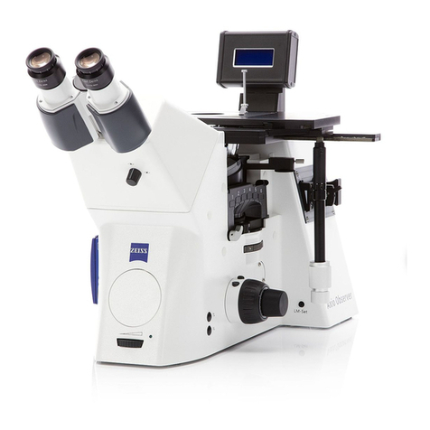
Carl Zeiss Copyright / Trademarks Axio Vert.A1
6 431030-7044-001 05/2012
Fig. 3-1 Unpacking and Setup........................................................................................................41
Fig. 3-2 Attaching the Binocular Tube ............................................................................................41
Fig. 3-3 Inserting Eyepieces ............................................................................................................42
Fig. 3-4 Inserting an Eyepiece Reticle ..............................................................................................42
Fig. 3-5 Screwing Objectives in Place ..............................................................................................43
Fig. 3-6 Mounting the Mechanical Stage (Shown without Tube)......................................................44
Fig. 3-7 Mounting the Specimen Stage...........................................................................................44
Fig. 3-8 Underside of the Scanning Stage .......................................................................................45
Fig. 3-9 Upper Side of the Scanning Stage......................................................................................45
Fig. 3-10 Terminals on the Underside of the Scanning Stage .............................................................46
Fig. 3-11 Inserting the Condenser ....................................................................................................47
Fig. 3-12 Equipping the Reflector Turret ...........................................................................................49
Fig. 3-13 Attaching the HAL Illuminator ...........................................................................................50
Fig. 3-14 Changing the Halogen Lamp for Transmitted Light ............................................................51
Fig. 3-15 Attaching the LED Illuminator ............................................................................................52
Fig. 3-16 Attaching the HBO 50 Illuminator or the HBO 100 Illuminator ............................................53
Fig. 3-17 Adjusting HBO 50 .............................................................................................................54
Fig. 3-18 Adjusting HBO 100 ...........................................................................................................55
Fig. 3-19 Attaching the VIS-LED Illuminator ......................................................................................56
Fig. 3-20 Adjusting the VIS-LED Attachment Illuminator....................................................................56
Fig. 3-21 Attaching the HAL 100 Illuminator.....................................................................................57
Fig. 3-22 Adjusting the HAL 100 Illuminator .....................................................................................58
Fig. 3-23 Changing the Halogen Lamp.............................................................................................59
Fig. 3-24 Connecting and Switching on the Microscope....................................................................60
Fig. 3-25 Installing Diaphragms in the Modulator Disk of the Condenser ...........................................61
Fig. 3-26 Inserting and Changing Diaphragms in the Slider ...............................................................63
Fig. 3-27 Orienting the Slit Diaphragm in the Slider as a Function of the Position to the
Microscope Axis................................................................................................................63
Fig. 3-28 Changing a Filter Set in the FL P&C Reflector Module ........................................................64
Fig. 3-29 Installing Filters and Beam Splitters ....................................................................................65
Fig. 3-30 Opening the Reflector Module...........................................................................................65
Fig. 3-31 Changing the Beam Splitter...............................................................................................66
Fig. 3-32 Identification Features of the Beam Splitter ........................................................................66
Fig. 3-33 Changing the Beam-Splitting Mirror in the Intermediate Phototube ....................................67
Fig. 3-34 Mounting the Aqua Stop...................................................................................................68
Fig. 3-35 Changing the LED Module in the Axio Vert.A1 FL-LED Stand ..............................................69
Fig. 3-36 Mounting the Carrier for Transmitted Light Illumination .....................................................70
Fig. 3-37 Working with LD Objectives...............................................................................................71
Fig. 4-1 Height Stop of the Focusing Drive......................................................................................74
Fig. 4-2 Setting Bright Field............................................................................................................76
Fig. 4-3 Setting Phase Contrast ......................................................................................................77
Fig. 4-4 Centering the Phase Ring Diaphragm (Bright in the Condenser) to the Phase Ring
(Dark in the Objective).......................................................................................................77
Fig. 4-5 Setting VAREL Contrast .....................................................................................................79
Fig. 4-6 VAREL Contrast for Microtiter Plates ..................................................................................79
Fig. 4-7 VAREL Contrast Pupil Images.............................................................................................80
