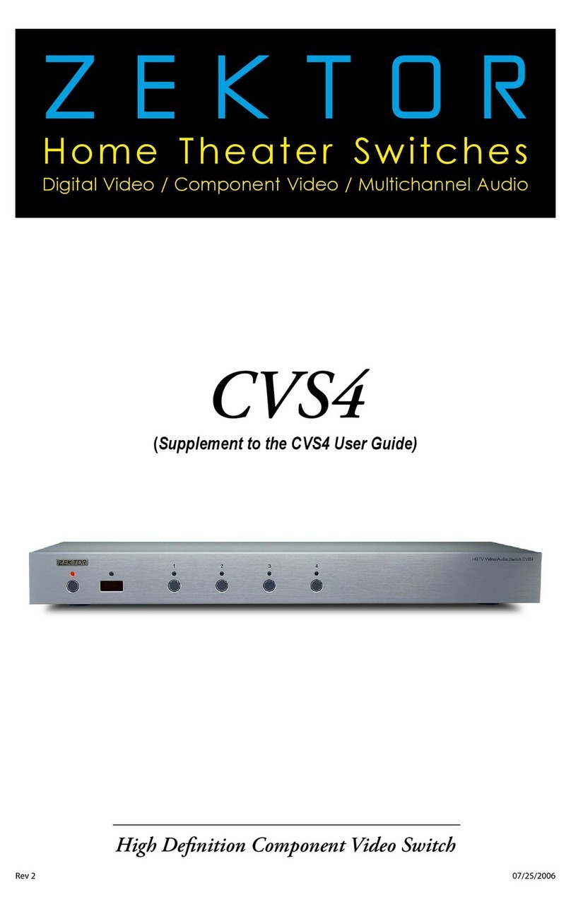
Zektor CVS4 User manual

ZEKTOR
Home Theater Switches
Digital Video / Component Video / Multichannel Audio
Rev 2 07/26/2006
High Definition Component Video Switch
CVS4

ii CVS4 Component Video Switch
1CVS4 Component Video Switch
Thank you for your purchase of your CVS4 High Definition Component
Video Switch.
Every care has been taken to assure you of a successful installation
and subsequent operations of your new CVS4 video switch, however
sh ould some th in g go w ron g, an d wa rr anty re pa ir work is need ed , we
req ue st t hat you h ol d on to t he o ri gi na l pack ag in g mater ia ls.
Ple as e ta ke t hi s ti me to v er if y the con tents o f th e CVS4 b ox.
The following should be included:
CV S4
Power Supply Module
Thi s Us er ’s M an ua l
If anything is missing please get in touch with us as soon as possible
so t hat w e ca n cor re ct t he s it ua tion.
1.
2.
3.
What’s Inside
Contents
What’s Inside ..................................... 1
An Overview of the CVS4.................... 3
Easy, Simple, Instructions! ................. 5
Three Simple Steps to a Remote! ........ 7
More Remote Options ........................ 9
Controlling the Front Panel Lights ... 11
Adjusting the Front Panel Intensity .. 13
Setting the Initial Power On State .... 15
Disabling Front Panel or Remote...... 17
Resetting to Factory Defaults........... 19
The RS-232 Port ............................... 20
K.I.S.S.™ (Keep It Simple Serial!™) .... 21
The Rear Panel IR Jack ..................... 23
Specifications.................................. 25
Warranty Policy ............................... 28
Contact Information ........................ 29

2CVS4 Component Video Switch
3CVS4 Component Video Switch
1
2
3
4
5
6
Front Panel Controls:
Power In di cat or. L ig ht s up i n st andby m od e.
Selection LEDs. Indicate currently selected inputs.
Input Selection Buttons.
In fr are d Re mo te S en so r Win dow.
In fr are d Re ce ive d Indi ca tor. Fla sh es w he n IR is received.
Power To gg le Bu tto n.
Rear Panel Connections:
Analog Inputs. Each input consists of six equivalent chan-
nels. The channels are colored and labeled for convenience,
however all six channels are of equivalent bandwidth and
functionality, and may be interchanged as desired.
Analog Outputs.
Digital Audio Inputs. Each input has an associated digital
audio channel with both a Coax and an Optical connection.
On ly one of the t wo t ypes o f in pu ts c an b e ac ti ve at a ny
ti me. The C VS 4 wi ll auto - se lect b et we en t he t wo t yp es of
signals. If a signal is supplied to both the Coax and Optical
in puts, t he Co ax s ignal i s gi ven p ri or it y.
IR Input. Accepts modulated or unmodulated IR signals.
R S- 23 2 Po r t.
Z-O UT c ur ren tl y un us ed, rese r ve d for f ut ure u se.
DC Power Ja ck Connec tor. P lug in th e su pp li ed p owe r
adapter into this jack.
Digital Audio Outputs. All digital audio inputs are automat-
ically converted to both Coax and Optical outputs. All three
outputs are available at all times, and are all individually
buffered to allow driving three different digital audio de-
vices simultaneously.
1.
2.
3.
4.
5.
6.
1.
2.
3.
4.
5.
6.
7.
8.
1 2 3 4
R/V L/H C/V
Y/G Pb/B Pr/R
R/V L/H C/V
Y/G Pb/B Pr/R
R/V L/H C/V
Y/G Pb/B Pr/R
R/V L/H C/V
Y/G Pb/B Pr/R
R/V L/H C/V
Y/G Pb/B Pr/R
DIGITAL
AUDIO
1 2 3 4 OUT
4 OUT OUT
1 2 3
9VDC
1 2 3 4 OUT
RS-232
IR / Z-IN Z-OUT
Front Panel
Rear Panel
An Overview of the CVS4
1
2
3
4
5
6
7
8

4CVS4 Component Video Switch
5CVS4 Component Video Switch
Step 1...
Use the analog input connections to switch component
video / composite video / analog audio or any combination
of the above signals to the CVS4’s analog output connec-
tor s. Us e th e di gital aud io c on ne ct or s to sw it ch d igi ta l au -
dio signals, with full format conversion between the optical
and coax digital audio formats.
If u si ng a h ard wi red IR co nt rol le r to oper ate t he C V S4 , con -
ne ct t he c ontro ll er IR cab le t o th e IR / Z-I N ja ck .
If u si ng a P C (o r ot her serial co nt rol le r) , con ne c t it to t he
RS-232 port using a standard serial cable.
Plug the power module into the CVS4, and plug the module
into a standard A.C. wall receptacle. The standby LED will
li ght u p.
Step 2...
To s wi tc h betwe en a ny of t he four inp ut s, simp ly p ress th e
bu tto n for t he d es ired in pu t. I f the C VS 4 is i n th e stand by,
it w ill turn on. Th e C VS4 wil l th en s wi tch to th e se le ct ed
input, and the associated LED will light to indicate this.
To p la ce t he C VS 4 ba ck i nto t he s ta nd by mo de, pre ss a nd
release the Power Toggle button. The channel LEDs will all
go b lank , an d th e st an dby L ED w il l li ght up. Press the Powe r
Toggle button again to re-select the previously selected
input.
Step 3...
Us e nearly an y remot e to co nt ro l you r CVS 4!
Usi ng a ny re mo te to o pe rat e th e CV S4 i s a si mp le m atter o f
pa ir in g up the C VS 4 wi th t he re mo te. The re mote do es n’ t
hav e to be a u ni versa l re mote (a lt ho ug h it can be), a ny re -
mo te fr om an old T V or VCR w il l work just f in e.
Using Zektor’s exclusive Intelligent-IR™, setup is easy! The
CV S4 d oe s al l th e wor k!
Turn to the next chapter for simple instructions
on how to pair up th e CVS4 with any remote!
•
•
•
•
•
•
•
•
•
Step 1: Make the appropriate connections.
R/V L/H C/V
Y/G Pb/B Pr/R
R/V L/H C/V
Y/G Pb/B Pr/R
R/V L/H C/V
Y/G Pb/B Pr/R
R/V L/H C/V
Y/G Pb/B Pr/R
R/V L/H C/V
Y/G Pb/B Pr/R
DIGITAL
AUDIO
1 2 3 4 OUT
4 OUT OUT
1 2 3
9VDC
1 2 3 4 OUT
RS-232
IR / Z-IN Z-OUT
To
Cable
Box
To
Cable Box
Digital Audio
To
DVD
To
Game
Console
To Game
Console
Digital Audio
Unused
Input
To
Projector
or
Monitor
To Power
Module
To
Composite
Monitor
w/Analog
Audio
To Home Theater
Receiver’s Digital
Audio Input
To DVD
Digital Audio
Step 2: Press buttons to select an input.
1 2 3 4
Step 3: Or use nearly ANY remote to select an input.
1 2 3 4
1 2 3
4 5 6
7 8 9
0
+ +
_ _
POWER
VOL CH
Turn to the next chapter for simple instructions
on how to setup the CVS4 for use with
any existing remote!
Easy, Simple, Instructions!

6CVS4 Component Video Switch
7CVS4 Component Video Switch
ree Simple Steps to a Remote!
The C V S4 fe at ure s Zek to r ’s Exc lu sive In te lligent -I R™, and wit h ve r y
few e xce ptions ca n be s et up t o use any re mo te yo u ca n po int at it !
Pick a remote, any remote!
St ar t by p ic k in g th e rem ote you’d li ke to use w it h th e C VS4.
If t he remote you pl an o n us in g is n ot p rog ram ma bl e (fo r
in stance, fr om a n old T V ), sk i p th e next s te p.
If y ou plan on us in g a un ive rs al remote, s ta r t by s et ting it
up a s a rem ote for a T V or VCR t hat y ou do not own . (For
in stance if you do n’t own a So ny T V, s et up yo ur u ni ver sa l
rem ot e to co ntrol a S ony T V.)
Step 1: Put the CVS4 into the Setup Mode
The C V S4 i s place d in to th e se tu p mo de by pre ss ing and
holding the Power button for about 4 seconds.
Step 2: Select the Intelligent-IR™ Learn Mode
The re a re ma ny op ti on s ava il ab le i n the setup m od e, but for
now a ll w e’re i nte reste d in i s th e In tellige nt -IR™ lear ni ng
mode. This is selected by pressing the ‘1’ button.
Once the ‘1’ button is pressed, the standby LED will flash
sl owe r and all t he o th er L ED s wi ll tur n off. The C VS 4 is
now w ai ti ng fo r ne w IR code s to b e se nt fr om yo ur remo te
con trol.
Step 3: Teach the CVS4 your new remote control codes
On yo ur remo te cont rol, pre ss t he foll ow in g butto ns, i n th e
following order:
Power 1 2 3 4 8 9 0
Tha t ’s it! The C VS 4 wi ll retu rn to th e st ate i t wa s in b efo re
se tup, and w il l now wor k wi th yo ur n ew remo te !
e new control buttons on your remote are...
Power Toggl es t he C VS4’s p owe r.
1 - 4 Selects inputs 1 through 4.
8Turn s on the C VS 4 (D is cre te ON)
9Turn s off the CV S4 ( Di screte OFF).
0Sequences through inputs.
No te: All r em ote c ont ro l cod es a re sa ved i n no n-vol ati le
memory and will not be lost during a power failure.
•
•
•
•
•
•
•
1 2 3 4
Step 1: Put the CVS4 into the Setup Mode
Press and hold the Power Button for 4 secs.
The standby LED will blink wildly, and the
selection LEDs will start sequencing to the
right. (You’ll know it when it happens!)
Step 2: Press the ‘1’ button for Intelligent-IR™ learning
1 2 3 4
Once the ‘1’ button
is pressed...
Step 3: Teach the CVS4 its new IR codes
1 2 3 4
1 2 3
4 5 6
7 8 9
0
+ +
_ _
POWER
VOL CH
Press the following sequence of buttons on
your remote control:
Power 1 2 3 4 8 9 0
That’s it! The CVS4 now operates with your
new remote control!
...the standby LED will flash slower,
and all the other LEDs will turn off.

8CVS4 Component Video Switch
9CVS4 Component Video Switch
More Remote Options
Front panel LED sequencing while learning
During the learning process, as each button of the remote is
pre ss ed, t he f ront pa ne l LE Ds w il l sequenc e. At a ny given t im e, th e
LED(s) that are slowly flashing, indicate the function the CVS4 is cur-
rently waiting to learn. The sequence is:
Standby LED Wa it in g for Power Tog gl e IR code.
'1 ' - LED Wa it in g for t he ' 1' I R code.
'2 ' - LED Wa it in g for t he ' 2' I R code.
'3 ' - LED Wa it in g for t he ' 3' I R code.
'4 ' - LED Wa it in g for t he ' 4' I R code.
Sta nd by & ' 1' LEDs Wa it in g for d is cre te O N code.
Sta nd by & ' 2' LEDs Wa it in g for d is cre te O FF code .
Sta nd by & ' 3' LEDs Waiting for input sequence code.
If the LEDs do not sequence, and the IR LED does not flash, when a
bu tto n is p resse d on t he remo te, t he n th e CVS4 doe s no t recog nize
th e IR co de b ei ng s ent. M ake sure th e rem ot e's bat te ri es a re fresh .
The C V S4 w ill wor k wi th m os t rem otes, h owe ver t he re ar e a few
exceptions. Some technical reasons for not working with some re-
mo tes a re: The re mo te m ay be u si ng a c ar ri er f req ue nc y o ut si de the
ran ge o f th e C VS4 (34 KH z to 42K H z), or it may b e us in g one of the
few protocols the CVS4 does not understand, like the Philip's RC5
an d RC6 pro tocol s.
If t he C VS4 does n ot l ea rn t he remo te codes yo u are u si ng, you will
hav e to us e an ot he r rem ot e, or i n th e ca se of using a u ni versal re -
mo te, yo u' ll h ave to p ic k a di ffe re nt ma nu fa cturer 's co de.
Skipping or Deleting IR codes
Du ri ng t he IR lea rnin g pr oce ss you can ch oo se t o delete th e cu rrent
cod e (d is ab le I R for t ha t func ti on ) or s kip th e cu rr ent cod e (l eav e it
unchanged) by pressing the '3' or '4' buttons:
'3' Disable IR for current function.
'4' Sk ip cur re nt co de, lea ve it u nc ha ng ed.
1 2 3 4
1 2 3
4 5 6
7 8 9
0
+ +
_ _
POWER
VOL CH
The IR LED will flash...
...and the LEDs will sequence each time a
remote control button is pressed if the IR
code is compatible with the CVS4.
1 2 3 4
1 2 3
4 5 6
7 8 9
0
+ +
_ _
POWER
VOL CH
Skip current code
(Leave IR unchanged)
Disable IR for current func-
tion being learned.
Front panel LED sequencing while learning
Skipping or Deleting IR codes

10 CVS4 Component Video Switch
11CVS4 Component Video Switch
Controlling the Front Panel Lights
The re a re fou r di ffe re nt fr ont pan el l ig ht m odes av ai lable on th e
CV S4 . Th ey are :
Front panel lights automatically fade from bright to dim
af te r 4 se con ds o f in ac tivi t y.
Front pan el l ig ht s are a lw ays a t the br ight le vel.
Front pan el l ig ht s are a lw ays a t the dim lev el.
Front pan el l ig ht s are t ur ne d of f.
Note: The intensities of the both the bright and dim levels can be
adjusted as well, this is explained in the next chapter.
To change the front panel lighting mode...
Step 1: Enter the Setup Mode
The C V S4 i s place d in to th e se tu p mo de by pre ss ing and
holding the Power button for about 4 seconds.
Step 2: Select the Lighting Mode option
Press the ‘3’ button to select the “Lighting Mode” option.
The front panel selection LEDs now indicate the currently
selected light mode as follows:
If ‘1’ is lit , th en f ron t pa ne l li ght s ar e always off.
If ‘2’ is lit , th en f ron t pa ne l li ght s ar e always dim .
If ‘3’ is lit , th en f ron t pa ne l li ght s ar e always brigh t.
If ‘4’ is lit , th en f ron t pa ne l li ght s au to -fad e from bright t o
di m af te r 4 secon ds o f in ac ti vi ty.
Step 3: Choose a new lighting mode
Choose a new light control mode by pressing the associ-
ated selection button.
Pres s th e Powe r Bu tto n to s ave t he new mo de a nd return to
normal operations.
Note: The lighting mode setting is saved in non-volatile mem-
or y and is n ot a ffec te d by a po wer f ai lu re.
•
•
•
•
•
•
•
•
•
1 2 3 4
Step 1: Place the CVS4 into the Setup Mode
Press and hold the Power Button for 4 secs.
The standby LED will blink wildly, and the
selection LEDs will start sequencing to the
right.
Step 2: Select “Lighting Mode” option
1 2 3 4
After ‘3’ is pressed, the standby
LED continues to flash, and the
front panel will display the cur-
rent Light Mode setting.
Step 3: Choose a new lighting mode
1 2 3 4
Auto-Fade
Always Bright
Always Dim
Always Off
Exit Setup Mode

12 CVS4 Component Video Switch
13CVS4 Component Video Switch
1 2 3 4
Step 1: Place the CVS4 into the Setup Mode
Press and hold the Power Button for 4 secs.
The standby LED will blink wildly, and the
selection LEDs will start sequencing to the
right.
Step 2: Select “Front Panel Intensity” option
1 2 3 4
After ‘4’ is pressed, the standby LED con-
tinues to flash, and the front panel will
display the current intensity setting.
Step 3: Adjust front panel intensities
1 2 3 4
Press to Brighten LEDs
Press to Dim LEDs
Selects BRIGHT level
Selects DIM level
Exit Setup Mode
Adjusting the Front Panel Intensity
The b ri gh t an d di m le vel s of t he f ron t pa nel light s of t he C VS 4 ar e
user adjustable, allowing the CVS4 to blend into a wide range of
lighting conditions.
To change the front panel intensities...
Step 1: Enter the Setup Mode
The C V S4 i s place d in to th e se tu p mo de by pre ss ing and
holding the Power button for about 4 seconds.
Step 2: Select the Front Panel Intensity option
Pres s th e ‘4 ’ but ton to se le ct “Fron t Panel I nte ns it y ” op ti on .
The front panel selection LEDs now indicate the front panel
intensity settings:
If ‘1’ is lit, then the DIM level is being adjusted.
If ‘2’ is lit, then the BRIGHT level being adjusted.
‘3 ’ and ‘4’ are al way s lit .
Step 3: Adjust Front Panel Intensities
Use t he ‘ 1’ an d ‘2 ’ but to ns to s wi tc h betwe en t he D IM a nd
BRIGHT settings.
Use t he ‘ 3’ bu tt on to d ec rease the i nt ensit y o f the fro nt
panel lights.
Use t he ‘ 4’ bu tt on to i nc rease the i nt ensit y o f the fro nt
panel lights.
You cannot make the DIM level brighter than the BRIGHT
level, and you cannot make the BRIGHT level dimmer than
th e DIM level.
Once the front panel intensities are acceptable, press the
Power but to n to sa ve th e ne w se tt in gs a nd exit t he s et up
mode.
Note: The new intensity settings are saved in non-volatile
me mory a nd a re n ot affe c ted b y a powe r fa il ure.
•
•
•
•
•
•
•
•

14 CVS4 Component Video Switch
15CVS4 Component Video Switch
1 2 3 4
Step 1: Set the CVS4 to the preferred initial power on state
Setup the CVS4 to the
initial power on state
you’d prefer.
Step 2: Save the new initial power on state
1 2 3 4
Start by pressing and
holding the Power
button...
Setting the Initial Power On State
As long as the CVS4 is plugged in, it will remember the previously
se lect ed i nput in s ta nd by m ode. When power ed u p by pr essing th e
Power button, it will return to that previously selected channel.
How eve r, if power is r em oved (fo r in stanc e a pl ug s tr ip u sed to po w-
er the CVS4 is turned off ), and then re-applied, the CVS4’s default
be hav io r is to ent er i nto t he s ta nd by mo de.
It is possible to change the power on behavior of the CVS4.
To change the power on defaults...
Step 1: Setup the CVS4 to your preferred power on state
.
Use t he f ront pa ne l bu ttons t o se tu p th e CV S4 t o the oper-
ating s et ti ng s you’d li ke a t in it ial power up.
Step 2: Save the new initial power on state.
Firs t press and h ol d th e Powe r butto n.
Whi le c ontinui ng t o ho ld t he Powe r bu tt on, pre ss a nd h old
the ‘1’ button.
After holding both buttons for about ‘4’ seconds, the dis-
play will blink indicating the new power on defaults have
be en acce pte d.
Test the new initial power on state
You can test the new defaults by either disconnecting the
pow er s upply f ro m the back of t he C V S4 or by un pl ug gin g
th e pow er supp ly f rom the wal l.
Re conne c t pow er. The C VS 4 wi ll p owe r up i nto your n ew
pow er o n defau lt s ta te.
•
1.
2.
3.
•
•
12...while continuing to hold the Power
button, press and hold the‘1’ button.
After about 4 seconds, the display will
flash indicating the new power on state
has been accepted.
3

16 CVS4 Component Video Switch
17CVS4 Component Video Switch
Step 1: Enter the Enable / Disable Control State
1 2 3 4
Start by pressing and
holding the Power
button...
12...while continuing to hold the Power
button, press and hold the‘4’ button.
After about 4 seconds, the standby LED
will flash quickly, and the display will indi-
cate the current enable / disable statuses.
3
Disabling Front Panel or Remote
If y ou are no t pl an ning on u si ng a remote c ont ro l with yo ur C VS 4,
you m ig ht want t o di sable i ts r emote c ontro l fu nc ti on .
Or if you have a household with young curious fingers that likes
playing with buttons, you also have the capability of disabling the
front panel switches and only operating the CVS4 with a remote.
To enable/disable the front panel switches or remote capabilities...
Step 1: Enter the Enable / Disable control state
Firs t press and h ol d th e Powe r butto n
Whi le c ontinui ng t o ho ld t he Powe r Bu tt on, pre ss a nd h old
the ‘4’ button.
After holding both buttons for about ‘4’ seconds, the stand-
by LED will start flashing quickly indicating you are now
able to enable / disable front panel buttons and IR control
functions.
The f ro nt pa ne l se le ctio n LE Ds n ow indica te t he stat e of t he
front panel and IR control settings:
If ‘ 3’ is l it , th en t he Fro nt Pan el b ut ton s ar e ENABLED.
If ‘4’ is lit, then the IR remote functions are ENABLED.
Step 2: Enable or Disable Front Panel and / or IR control
Use the ‘3’ button to ENABLE / DISABLE the front panel
buttons.
Use t he ‘ 4’ bu tt on to E NA BL E / DI SA BL E the IR re mo te co n-
trol functions.
Whe n fi ni sh ed, p re ss the ‘Pow er ’ b utton t o sav e new set-
tings and return to normal operations.
Note: Disabling the front panel buttons does not disable the
ab ilit y to en ter the Se tup Modes . Even w it h th e fro nt
pa nel disab le d you c an p er fo rm t he a bove ste ps, allow-
ing you to once again enable the front panel buttons.
1.
2.
3.
•
•
•
•
Step 2: Enable or Disable Front Panel and / or IR Control Functions
1 2 3 4
Enable / Disable
IR Control Functions
Enable / Disable
Front Panel Buttons
Exit Setup Mode

18 CVS4 Component Video Switch
19CVS4 Component Video Switch
Step 1: Reset All Parameters to Factory Defaults
1 2 3 4
Start by pressing and
holding the Power
button...
12...while continuing to hold the Power
button, press and hold both the‘2’
and the ‘3’ buttons.
After about 4 seconds, the display will flash
indicating all parameters have been restored
to their factory programmed values.
3
Resetting to Factory Defaults
If, fo r whate ver r ea son, yo u’d l ik e to re set you r CV S4 b ac k to i ts fac -
tory condition, this is easily done...
Step 1: Reset All Parameters to Factory Defaults
Firs t press and h ol d th e Powe r butto n
Whi le c ontinui ng t o ho ld t he Powe r Bu tt on, pre ss a nd h old
both the ‘2’ and ‘3’ buttons.
After holding all buttons for about ‘4’ seconds, the display
will flash indicating all parameters have been restored to
their factory programmed values.
1.
2.
3.

20 CVS4 Component Video Switch
21CVS4 Component Video Switch
K.I.S.S.™ (Keep It Simple Serial!™)
Zektor’s exclusive K.I.S.S.™ (Keep It Simple Serial™) protocol was de-
signed by engineers who have been controlling RS-232 devices for
most of their careers and understand the pitfalls of a badly designed
pro to col .
A few features of the K.I.S.S.™ protocol are:
A simple and logically consistent command structure.
Fully bi-directional operations and can operated in both
a Master Slave mode (only responds when spoken to), or
in an Asynchronous mode (state changes are sent as they
occur).
All commands and responses can optionally use a checksum
or a CRC-8 checkcode to insure reliable communications.
A com ma nd w il l al way s generate a res po ns e! Th ere are n o
“t im eo ut ” st ate s as p ar t o f th e proto col. A ti me ou t will al -
way s indicat e so me t yp e of p hysical co nn ec ti on e rr or ( loose
cable, extreme noise, etc.).
Commands and responses have been designed for simple
parsing in any language.
Ea sy to t es t us ing a ter mi na l, or t er mi na l em ulati on s of t-
ware. (H yper term, S ecure CR T, et c.)
A few features of the CVS4 command set are:
A full featured command set that goes far beyond simple
fro nt p an el co nt rol o pe ratio ns ! Al lows fu ll c ont ro l ove r all
fea tu res o f th e CV S4 .
Full notification of any state changes. Did the user just
change the front panel LED intensities? The controller can
be notified of this.
The a bi li ty t o di sa bl e the fro nt panel, a nd s till ha ve fr ont
panel button presses sent to the serial port.
The a bi li ty t o read al l IR c od es sent t o th e CV S4 b y any
rem ot e, eve n th os e no t us ed by t he C V S4. Use t he C VS4 to
ad d IR co nt rol t o any p roj ec t !
Ma ny mo re f ea tures, too n um ero us t o li st h ere ...
For a full description of K.I.S.S.™ and a list of the commands sup-
ported by the CVS4, download the CVS4 supplemental manual at:
www.zektor.com/cvs4/downloads.htm
•
•
•
•
•
•
•
•
•
•
•
The R S-23 2 on t he C VS4 is the s am e for mat as a P C- mo de m, and uses
the same type cable as a serial modem would, which is a standard
st rai gh t th rou gh c ab le. D o no t us e a ca bl e th at is m ar ke d as a “ Nu ll
Modem” cable.
The C V S4 c an also be us ed w it h any U SB t o RS -2 32 co nve rs io n cable,
these are all typically straight through cables.
The RS-232 port is a female type DE-9 connector (sometimes mistak-
en ly re fer re d to as a D B-9 co nn ec to r) w it h the fol low in g pi no ut :
5 4 3 2 1
9 8 7 6
Pin definitions:
1 - No Conn ec t 6 - No Conn ec t
2 - TX 7 - No Conn ec t
3 - RX 8 - No Conn ec t
4 - No Conn ec t 9 - No Conn ec t
5 - GND
The p or t s et ti ng s us ed by t he C V S4 are:
Baudrat e: 9 60 0
Data Bi ts : 8
Stop Bi ts : 1
Parity: N ON E
The communications protocol used is Zektor’s exclusive K.I.S.S.™
(Keep It Simple Serial™) protocol.
e RS-232 Port

22 CVS4 Component Video Switch
23CVS4 Component Video Switch
e Rear Panel IR Jack
The rear panel jack labeled "IR / Z-IN" allows the CVS4 to be controlled by
hardwired IR controllers.
The signal can be either modulated or unmodulated:
25KHz to 250KHz
+3V to +12V
0V
MODULATED SIGNAL
UNMODULATED SIGNAL
+3V to +12V
0V
And uses a standard 1/8" (3.5mm) mini-plug:
GND
SIGNAL
+3V to +12V
The signal voltage can range from +3V to +12V, with a nominal value of +5V
recommended.
The signal can be either unmodulated, or modulated with a modulation fre-
quency ranging from 25KHz to 250KHz.
The IR jack recognizes the same IR codes as the front panel IR sensor.

24 CVS4 Component Video Switch
25CVS4 Component Video Switch
Specifications
Analog Channels
Bandwidth @ -0.1db:
Bandwidth @ -3db:
Resolution:
Input Coupling:
Output Coupling:
Digital Audio Channels
Inputs:
Outputs:
Maximum Transfer Rate:
Digital Audio Modes:
Coax Input Level Range:
Coax Output Level:
IR Jack:
Serial Port:
Power Requirements:
Optional International:
Power Supply:
Dimensions:
Warranty:
0Hz - 70MHz, All channels
Greater than 200MHz, All channels
480i - 1080p, All HDTV modes
D.C.
D.C.
4 Coax, 4 Optical, (Auto conversion between formats)
2 Coax, 1 Optical, (Simultaneous)
13.2Mb/S
PCM, DD5.1, DTS, All modes
200mV - 7.0V (PC Soundcard Compatible)
500mV Nominal
+3V to +12V, Un-Mod. or 25KHz to 250KHz Mod. Freq.
9600 Baud (8N1)
90-120VAC, 60Hz, 15W
90-264VAC, 47-63Hz, 15W
Wall Mount, 9V @ 500ma, U.L. Listed
Rack Mountable, 17”W x 6.5”D x 1.75”H
Two Year Parts and Labor
Specifications:

26 CVS4 Component Video Switch
27CVS4 Component Video Switch
This page left intentionally (nearly) blank. This page left intentionally (nearly) blank.

28 CVS4 Component Video Switch
29CVS4 Component Video Switch
Contact Information
Instructions for Returning Items
Ple as e retain th e da ted sales r ece ip t as e vi de nce o f th e da te of
pu rch as e. Yo u wi ll n eed it fo r any w ar ran ty ser vice . If you boug ht
the product through a dealer, installer, or reseller, you will need to
ret ur n th e produ c t to the po in t of s al e.
E-mail us, or call us, using the information listed under “Customer
Se r vi ce Co nt ac t I nfo rm ation”, fo r a Re turn to M anuf ac t ure r Aut ho ri -
zation (RMA) number. Describe briefly the reasons for your request-
ed re tu rn .
Yo u mu st re ce ive a n RMA # b efore yo u re turn a ny go od s to us . The
RMA # must appear on your return packing label or on the outside
of t he box. M erc ha nd is e wi th out a RMA # w il l be re fu se d. RM A’s are
valid f or t wen ty (20 ) da ys fr om d ate o f is su ance.
All returned merchandise must be shipped in the original packaging.
If i t is n ot i n th e or igina l pa ck a ging, ZEK TOR w il l no t be held lia bl e
for damage during shipment. Shipments of returns must be prepaid,
an d we wi ll n ot a cce pt CO D ret ur ns.
Customer Service Contact Information:
Zektor
12675 Danielson Ct.
Suite 401
Poway, CA 92064
Phone: 858-748-8250
Fax: 858-748-8224
E-mail: customerservice@zektor.com
Website: www.zektor.com
Warranty Policy
Warranty Policy
ZE K TOR wa rr ant s th is p roduc t a ga inst defe ct s in m aterial a nd w or k-
ma nship und er n or ma l us e an d se r vi ce fo r two yea rs f rom t he o ri gi-
nal date of purchase. ZEKTOR, at its option, shall repair or replace
th e defec ti ve u nit cove red by th is w ar ran ty.
In o rder to k ee p th is warran ty i n ef fec t , th e pro du ct must ha ve be en
handled and used as prescribed in the instructions accompanying
th is wa rran ty. This wa rr an ty d oe s no t cove r any damag e du e to a cci -
de nt, m is us e, ab us e, or n eg li ge nce. Thi s wa rr ant y i s val id o nl y if t he
product is used as specified in the product documentation.
Re pa ir o r rep la cem en t, a s pro vi ded under t hi s wa rr ant y, is yo ur
exclusive remedy. ZEKTOR shall not be liable for any incidental or
consequential damages. Implied warranties of merchantability and
fitness for a particular purpose on this product are limited in dura-
ti on to t he d ur ati on o f th is w ar ranty.
Some states/countries do not allow the exclusion or limitation of
incidental or consequential damages, so the above limitation or
exc lu sion may no t ap pl y to yo u. Some s ta tes/c ou ntri es do not al-
low l im it at ions on how l on g an i mplied wa rr anty l as ts, s o th e ab ove
li mitat io n may not a pp ly t o you . Thi s wa rrant y gi ves you s pe cific
le gal ri ght s, and yo u may a ls o ha ve ot he r ri ghts that v ar y f rom s ta te
to st at e and cou nt r y to co un tr y.
Return & Exchange
Shipment of product is as advertised by product. Upon receipt of
merchandise inspect product carefully, should you find that the
product does not meet your expectations, or satisfaction, contact
us at onc e an d tell us y ou r con ce rn s, so we may m ak e eve r y ef for t to
satisfy your purchase.

ZEKTOR
ZEKTOR
12675 Danielson Ct
Suite 401
Poway, CA 92064
858•748•8250
www.zektor.com
Other manuals for CVS4
2
Table of contents
Other Zektor Switch manuals

Zektor
Zektor CVS4 Owner's manual

Zektor
Zektor HDVI5 User manual

Zektor
Zektor HDMI5 User manual

Zektor
Zektor HDVI5 User manual

Zektor
Zektor ZEKTOR MAS3 User manual

Zektor
Zektor HDS4.2 User manual

Zektor
Zektor MAS7.1 User manual

Zektor
Zektor DVS5.1 User manual

Zektor
Zektor HDVI5 User manual

Zektor
Zektor HDVI5 User manual
Popular Switch manuals by other brands

Siemens
Siemens Powers SW 141 Series Technical instructions

Korenix
Korenix JetNet 3212G-2C2F user manual

TRENDnet
TRENDnet TEG-S8 - Gigabit Switch Specifications

HP
HP PROCURVE 6120 Management and configuration guide

D-Link
D-Link DGS-3000 series Hardware installation guide

SONIQ
SONIQ VHT100-AU instruction manual