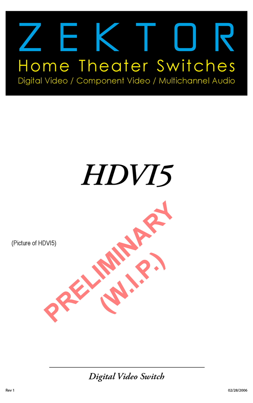
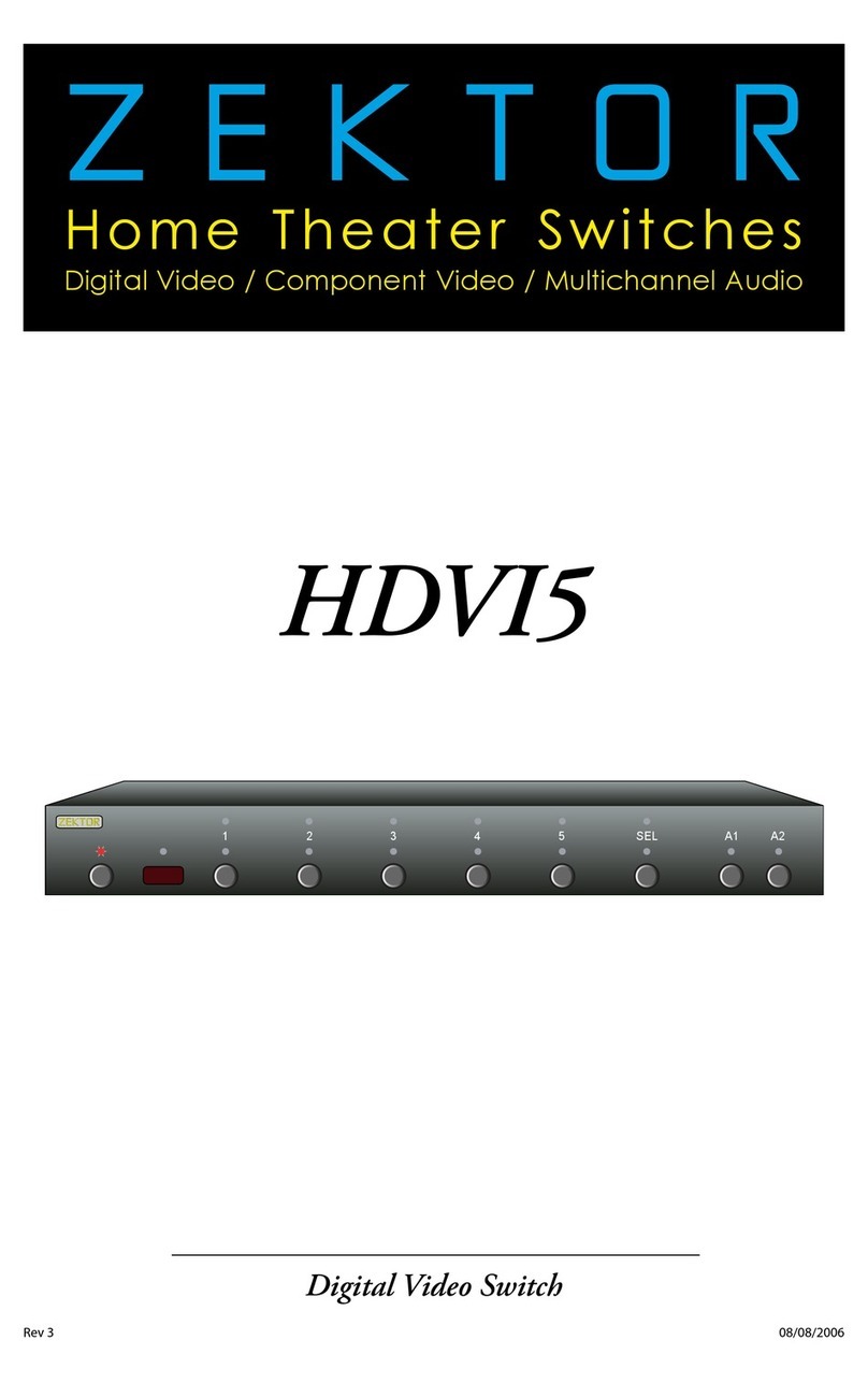
Zektor HDVI5 User manual

ZEKTOR
Home Theater Switches
Digital Video / Component Video / Multichannel Audio
Rev 1 02/28/2006
Digital Video Switch
(Picture of HDVI5)
HDVI5
PRELIMINARY
(W.I.P.)
All manuals and user guides at all-guides.com
all-guides.com

ii HDVI5 Component Video Switch
1HDVI5 Component Video Switch
Thank you for your purchase of your HDVI5 High Definition Compo-
nent Video Switch.
Every care has been taken to assure you of a successful installation
and subsequent operations of your new HDVI5 video switch, however
should something go wrong, and warrant y re p a i r work is needed, we
re q u e s t t h at you hold on to the original packaging materials.
Pl e a s e t a k e t h i s t i m e t o verify the conte n t s o f t h e H D V I 5 b ox.
The following should be included:
HDVI5
Power Supply Module
Th i s User ’s Manual
If anything is missing please get in touch with us as soon as possible
so that we can correct the situation.
1.
2.
3.
What’s Inside
Contents
What’s Inside ..................................... 1
An Overview of the HDVI5.................. 3
Easy, Simple, Instructions! ................. 5
Three Simple Steps to a Remote! ........ 9
Controlling the Front Panel Lights ... 11
Adjusting the Front Panel Intensity .. 13
Setting the Initial Power On State .... 15
Disabling Front Panel or Remote...... 17
Changing Switching Delays.............. 19
Input Cable Length Tuning ............... 21
Bandwidth & Sync Settings............... 23
Resetting to Factory Defaults........... 25
The RS-232 Port ............................... 26
K.I.S.S.™ (Keep It Simple Serial!™) .... 27
The Rear Panel IR Jack ..................... 29
Specifications.................................. 31
Warranty Policy ............................... 32
Contact Information ........................ 33
All manuals and user guides at all-guides.com

2HDVI5 Component Video Switch
3HDVI5 Component Video Switch
1
2
3
4
5
6
7
8
Front Panel Controls:
Power I nd i c a tor. Lights up in standby mode.
Selection LEDs. Indicate currently selected inputs.
Select between Normal/Audio/Video Breakaway.
Toggle Auxilar y Relays.
Input Selection Buttons.
Infrare d R em o t e S e n s o r Window.
Infrare d R ec e i ved I n d i c ator. Flashes when IR is re c e i ved.
Power Toggle Butto n .
Rear Panel Connections:
DVI Inputs. DVI or HDMI (when using conversion cable)
compatible digital inputs. All inputs are fully HDCP compat-
ible with both DVI and HDMI formats. All inputs are fully
HDMI audio compatible.
DVI Output.
Digital Audio Inputs. Each input has an associated digital
audio channel with both a Coax and an Optical connection.
Only one of the two types of inputs can be ac t i ve at any
time. The HDVI5 will auto -select bet ween the t wo t y p e s o f
signals. If a signal is supplied to both the Coax and Optical
inputs, t h e Coax signal is gi ven pr i o r i t y.
IR Input. Accepts modulated or unmodulated IR signals.
R S- 23 2 Po r t.
Z-OUT cur rently unused, reser ved for future use.
DC Power Jack Connec tor. Plug in the supplied powe r
adapter into this jack.
Digital Audio Outputs. All digital audio inputs are automat-
ically converted to both Coax and Optical outputs. All three
outputs are available at all times, and are all individually
buffered to allow driving three different digital audio de-
vices simultaneously.
1.
2.
3.
4.
5.
6.
7.
8.
1.
2.
3.
4.
5.
6.
7.
8.
1 2 3 4 5 SEL A1 A2
(Picture of rear panel)
Front Panel
Rear Panel
An Overview of the HDVI5
1
2
3
4
5
6
7
8
All manuals and user guides at all-guides.com

4HDVI5 Component Video Switch
5HDVI5 Component Video Switch
Initial Setup...
Use the analog input connections to switch component
video / composite video / analog audio or any combination
of the above signals to the HDVI5’s analog output connec-
to r s. Use the digital audio co n n e c tors to s w i tch digital au-
dio signals, with automatic conversion between the optical
and coax digital audio formats.
If using a hardwire d I R controller to o p e rate the HDVI5,
co n n e c t the cont roller IR cable to the IR / Z-IN jack.
If using a PC (or other serial contro l l e r ) , connec t it to t h e
RS-232 port using a standard serial cable.
Plug the power module into the HDVI5, and plug the mod-
ule int o a s t a n d a rd A.C. wall re c e p t a c l e. Th e s t a n d by LED
will light u p.
Selecting an Input...
To switc h b e t ween any of the five i n p u t s, simply press the
button for the desired input. If the HDVI5 is in the standby,
it will turn on. Th e H D V I 5 w i l l t h e n s w i tch to the selec ted
input, and the associated LED will light to indicate this.
To place t h e H D V I 5 b a c k i nto the standby mode, p ress and
release the Power Toggle button. The channel LEDs will all
go blank, and the standby LED will light up. Press the Power
Toggle button again to re-select the previously selected
input.
Audio / Video Breakaway...
To break aw ay the audio or video (to listen to t h e a u d i o
from one input while view the video from another), press
the SEL key. When both the RED and BLUE LEDs above t h e
SEL button are lit, then the audio and video inputs will be
switched simultaneously. When only the RED LED is lit, then
only the Audio will be switch. Similarly, when only the BLUE
LED is lit, only the video will be switched when pressing an
input button.
Note: Audio breakaway only applies to the digital audio con-
nections on the back of the HDVI5. You cannot break-
away the HDMI audio channel that i s s e nt ove r t h e H D M I
cable. HDMI audio will always follow the video signal.
•
•
•
•
•
•
•
Step 1: Make the appropriate connections.
(Picture of back of HDVI5)
Selecting an Input: Press numbered buttons to select an input.
1 2 3 4 5 SEL A1 A2
Easy, Simple, Instructions!
1 2 3 4 5 SEL A1 A2
Audio / Video Breakaway: Press SEL to toggle breakaway options.
Only red LED, above
the SEL button is lit,
so only Audio is
switched when
'4' is pressed.
All manuals and user guides at all-guides.com

6HDVI5 Component Video Switch
7HDVI5 Component Video Switch
Easy, Simple, Instructions!
Auxiliary Relay Connections...
Th e a u x i l i a r y relay c o ntac ts a re rated at 3 0 volts @ 5amps,
and can be used to s w i tch on and off anything yo u c a n
think of within those limits.
Each relay has a Normally Open connection, two Common
connections, and a Normally Closed connection.
Auxiliary Relay Operation...
Th e A 1 a n d A 2 b u t tons are used to to g g l e o n a n d o f f t h e
re l ays.
Th e relays can also be setup to t u r n o f f a f ter a gi v-
en amount o f t i m e. S e e ( TBD) chapte r for relay s e t u p
information.
Using a Remote Control...
Use nearly any remote to contro l your HDVI5!
Us i n g a ny remote to operate the HDVI5 is a simple mat-
te r o f p a i r in g u p t h e H D V I 5 w i t h t h e remote. The re m o t e
doesn’t have t o b e a u n i versal remote ( a l t h o u g h i t c a n b e ) ,
any remote fro m a n o l d T V o r VCR will work just fine.
Using Zektor’s exclusive Intelligent-IR™, setup is easy! The
HDVI5 does all the work!
Turn to the next chapter for simple instructions
on how to pair up the HDVI5 with any remote!
•
•
•
•
•
•
•
1 2 3 4 5 SEL A1 A2
1 2 3
4 5 6
7 8 9
0
+ +
_ _
POWER
VOL CH
Using a Remote Control: Use nearly ANY remote to select an input.
Turn to the next chapter for simple instructions
on how to setup the HDVI5 for use with
any existing remote!
(Picture of RELAY connections)
Auxiliary Relay Connections
1 2 3 4 5 SEL A1 A2
Auxiliary Relay Operation: Use A1 and A2 buttons to toggle relays.
All manuals and user guides at all-guides.com

8HDVI5 Component Video Switch
9HDVI5 Component Video Switch
ree Simple Steps to a Remote!
Th e H D V I 5 feature s Zektor ’s Exclusive Intelligent- I R ™ , a n d w i t h ver y
few exce p t i o n s c a n b e s e t u p t o u s e a ny re m o t e you can point at it!
Pick a remote, any remote!
Star t by pick ing the re m o te you’d like to u s e w i t h t h e
HDVI5. If the remote you plan on using is not progra m m a -
ble (for instance, from an old TV ), sk i p t h e n e x t step.
If you plan on using a unive r s a l remote, s t a r t by setting it
up as a re m o te for a T V or VCR that you do not own. (For
instance i f you don’t ow n a S ony T V, s e t u p your universal
re m o te to control a S o ny T V. )
Step 1: Put the HDVI5 into the Setup Mode
Th e H D V I 5 i s p l a ced into the setup mode by pre s s i n g a n d
holding the Power button for about 4 seconds.
Step 2: Select the Intelligent-IR™ Learn Mode
Th e re are many o p t i o n s available in the setup mode, b u t for
now a l l we’re i n terested in is the Intelligent - I R ™ l e a r n i n g
mode. This is selected by pressing the ‘1’ button.
Once the ‘1’ button is pressed, the standby LED will flash
slower and all the other LEDs will turn off. The HDVI5 is
now w a i t i n g for new IR codes to b e s e n t f rom your remote
co n t rol.
Step 3: Teach the HDVI5 your new remote control codes
On yo u r remote cont rol, pre s s t h e following butto n s, in the
following order:
Powe r 1 2 3 4 5 0 8 9
Th a t ’s it! Th e H D V I 5 w i l l return to the state i t w a s i n b e fore
setup, and will now wor k w i t h your new remote !
e new control buttons on your remote are...
Power Toggles the HDVI5’s power.
1 - 5 Selects inputs 1 through 5.
0Sequences the SEL butto n (A/V break away).
8Toggles Auxiliar y Relay 1.
9Toggles Auxiliar y Relay 2.
Note : Al l remote cont rol codes are s aved in non-volatile
memory and will not be lost during a power failure.
•
•
•
•
•
•
•
1 2 3 4 5 SEL A1 A2
Step 1: Put the HDVI5 into the Setup Mode
Press and hold the Power Button for 4 secs.
The front panel LEDs will start to blink
wildly... (You’ll know it when it happens!)
Step 2: Press the ‘1’ button for Intelligent-IR™ learning
1 2 3 4 5 SEL A1 A2
Step 3: Teach the HDVI5 its new IR codes
1 2 3 4 5 SEL A1 A2
1 2 3
4 5 6
7 8 9
0
+ +
_ _
POWER
VOL CH
Press the following sequence of buttons on
your remote control:
Power 1 2 3 4 5 0 8 9
That’s it! The HDVI5 now operates with
your new remote control!
Once the 1 button is pressed, the
standby LED will flash slower, and
all the other LEDs will turn off.
All manuals and user guides at all-guides.com
all-guides.com

10 HDVI5 Component Video Switch
11HDVI5 Component Video Switch
Controlling the Front Panel Lights
Th e re are fo u r d i f fere n t f ront panel light modes av a i l a b l e o n t h e
HDVI5. They are:
Front panel lights automatically fade from bright to dim
after 4 seconds of inactivit y.
Fro n t p a n e l l i g hts are always at the bright level.
Fro n t p a n e l l i g hts are always at the dim level.
Fro n t p a n e l l i g hts are turned off.
Note: The intensities of the both the bright and dim levels can be
adjusted as well, this is explained on the next page.
To change the front panel lighting mode...
Step 1: Enter the Setup Mode
Th e H D V I 5 i s p l a ced into the setup mode by pre s s i n g a n d
holding the Power button for about 4 seconds.
Step 2: Select the Lighting Mode option
Press the ‘3’ button to select the “Lighting Mode” option.
The front panel selection LEDs now indicate the currently
selected light mode as follows:
If ‘1’s bl u e L E D i s l i t , t h e n f ront panel lights are always off.
If ‘2’s bl u e L E D i s l i t , t h e n f ront panel is always d i m .
If ‘3’s bl u e L E D i s l i t , t h e n f ront panel is always b r ig h t .
If ‘4’s bl u e L E D i s l i t , t h e n f ront panel lights auto-fade from
bright to d i m a f te r 4 s e c o n d s o f i n a c tivity.
Step 3: Choose a new lighting mode
Choose a new light control mode by pressing the associ-
ated selection button.
Press the Powe r B u t ton to save t h e n e w m o d e a n d return to
normal operations.
Note: The lighting mode setting is saved in non-volatile mem-
or y a n d i s n o t a f fec t e d by a power failure.
Turn to the next page for instruc tions on how to
adjust LED intensities...
•
•
•
•
•
•
•
•
•
1 2 3 4 5 SEL A1 A2
Step 1: Place the HDVI5 into the Setup Mode
Press and hold the Power Button until the
display goes wild. (About 4 seconds.)
Step 2: Select “Lighting Mode” option
1 2 3 4 5 SEL A1 A2
After ‘3’ is pressed, the standby
LED continues to flash, and the
front panel will display the cur-
rent Light Mode settings.
Step 3: Choose a new lighting mode
1 2 3 4 5 SEL A1 A2
Auto-Fade
Always Bright
Always Dim
Always Off
Exit Setup Mode
All manuals and user guides at all-guides.com

12 HDVI5 Component Video Switch
13HDVI5 Component Video Switch
1 2 3 4 5 SEL A1 A2
Step 4: Select between Bright and Dim settings: Use SEL button.
Step 5: Adjust Front Intensities.
1 2 3 4 5 SEL A1 A2
Use A1 and A2 to dim and brighten LEDs
A1 = Dim LEDs.
A2 = Brighten LEDs.
Adjusting the Front Panel Intensity
Continued from previous page...
If you have not already done so, per fo r m S teps 1 and 2 on the previ-
ous page.
Step 4: Toggle between Bright and Dim Settings
The 'SEL' LED indicates the front panel intensity settings:
If BLUE LED is lit, then the BRIGHT level is being adjusted.
If RED LED is lit, then the DIM level is being adjusted.
Us e t h e ' S E L' b u t t o n to toggle between bright and dim
settings.
Step 5: Adjust Front Panel Intensities
Us e t h e ‘A1’ butto n to decrease the intensity of the fro n t
panel lights.
Us e t h e ‘A2’ butto n to increase the intensity of the fro n t
panel lights.
You cannot make the DIM level brighter than the BRIGHT
level, and you cannot make the BRIGHT level dimmer than
the DIM leve l.
Step 6: Use the Power Button to Exit
Once the front panel intensities are acceptable, press the
Power button to save the new settings and exit the setup
mode.
Note: The new intensity settings are saved in non-volatile
memor y a n d a re not affected by a power failure.
•
•
•
•
•
•
Use the SEL button to toggle between
the BRIGHT and DIM settings.
1 2 3 4 5 SEL A1 A2
Step 6: Use the Power Button to Exit.
When things look good, press the
power button to exit setup mode.
All manuals and user guides at all-guides.com

14 HDVI5 Component Video Switch
15HDVI5 Component Video Switch
1 2 3 4 5 SEL A1 A2
Step 1: Set the HDVI5 to the preferred initial power on state
Setup the HDVI5 to the initial power on
state you’d prefer. In this case we want the
HDVI5 turn on and switch to Input 5 when
first plugged in.
Step 2: Save the new initial power on state
1 2 3 4 5 SEL A1 A2
Start by pressing and
holding the Power
button...
Setting the Initial Power On State
As long as the HDVI5 is plugged in, it will remember the previously
selected input in standby mode. When powered up by pre s s i n g t h e
Power button, it will return to that previously selected channel.
However, if power is re m oved (fo r i n s t a n ce a plug strip used to pow-
er the HDVI5 is turned off), and then re-applied, the HDVI5’s default
behav i o r i s to enter into t h e s t a n d by mode.
It is possible to change the power on behavior of the HDVI5.
To change the power on defaults...
Step 1: Setup the HDVI5 to your preferred power on state
.
Us e t h e f ront panel buttons to setup the HDVI5 to t h e o p e r-
at i n g s e t t i n g s you’d like at initial powe r u p.
Step 2: Save the new initial power on state.
First pre s s a n d h o l d t h e Power button.
Wh i l e c o ntinuing to hold the Powe r b u t t o n , p ress and hold
the ‘1’ button.
After holding both buttons for about ‘4’ seconds, the dis-
play will blink indicating the new power on defaults have
been accepted.
Test the new initial power on state
You can test the new defaults by either disconnecting the
power supply from the back of the HDVI5 or by unplugging
the power supply from the wall.
Reconnect powe r. The HDVI5 will power up into your new
power on default state.
•
1.
2.
3.
•
•
12...while continuing to hold the Power
button, press and hold the‘1’ button.
After about 4 seconds, the display will
flash indicating the new power on state
has been accepted.
3
All manuals and user guides at all-guides.com

16 HDVI5 Component Video Switch
17HDVI5 Component Video Switch
Disabling Front Panel or Remote
If you are u s i n g t h e rear panel IR jack , you might want to d i s a b l e t h e
IR sensors to p revent use of the re m o te contro l.
Or if you have a household with young curious fingers that likes
playing with buttons, you also have the capability of disabling the
front panel switches and only operating the HDVI5 with a remote.
To enable / disable the front panel switches or remote capabilities...
Step 1: Enter the Setup Mode
Th e H D V I 5 i s p l a ced into the setup mode by pre s s i n g a n d
holding the Power button for about 4 seconds.
Step 2: Enter the Enable / Disable control state
Wh i l e i n t h e s e t u p m o d e, press '4' to e n ter the Enable /
Disable co n t rol state. The curre nt status will be displaye d
using the front panel LEDs.
A Blue LED indicates an option is enabled, and Red LED
indicates disabled.
Step 3: Enable or Disable Front Panel and / or IR control
Us e ' 1 ' to enable / disable the IR Jack hardware.
Us e ' 2 ' to enable / disable the IR S e n s o r h a rdware.
Use '3' to enable / disable the front panel buttons.
Us e ' 4 ' to enable / disable IR control.
Note 1: When disabling the IR Jack and IR Sensor, the actual
hardware is disabled. Whereas 'IR Control' enables /
disables whether the HDVI5 responds to IR signals re-
ceived. The difference mostly concerns reading IR sig-
nals thro u g h t h e R S -232 por t. I f t h e I R S e n s o r a n d J a c k
are enabled, and 'IR Control' disabled, IR signals can still
be read through the RS-232 port, while being ignored by
the HDVI5.
Note 2: Disabling the front panel buttons does not disable the
ability to ent e r t h e S e t u p M o d e s. Even with the front
panel disabled you c a n p e r form the above steps, a l l ow-
ing you to once again enable the front panel buttons.
Note 3 : The new settings are s ave d i n n o n - volatile memor y a n d
are n o t a f fec te d by a power failure.
•
1.
2.
1.
2.
3.
4.
Step 3: Enable or Disable Front Panel and / or IR Control Functions
1 2 3 4 5 SEL A1 A2
Enable / Disable IR Control
Enable / Disable Buttons
Enable / Disable IR Sensor
Enable / DIsable IR Jack
Exit Setup Mode
1 2 3 4 5 SEL A1 A2
Step 1: Place the HDVI5 into the Setup Mode
Press and hold the Power Button until the
display goes wild. (About 4 seconds.)
Step 2: Enter the Enable / Disable control state.
1 2 3 4 5 SEL A1 A2
After ‘4’ is pressed, the standby
LED continues to flash, and the
front panel will display the cur-
rent settings.
All manuals and user guides at all-guides.com

18 HDVI5 Component Video Switch
19HDVI5 Component Video Switch
Changing Switching Delays
The HDVI5 allows adjusting the switching delay times, for Video and
Audio, independently. By default the HDVI5 uses a 200ms video de-
lay and no audio delay when switching between channels. The HDMI
specifications calls for a minimum of 100ms, some monitors may
require much larger delay times to switch reliably.
To adjust the Audio / Video switching delays...
Step 1: Place the HDVI5 into the Setup Mode
Th e H D V I 5 i s p l a ced into the setup mode by pre s s i n g a n d
holding the Power button for about 4 seconds.
Step 2: Enter the Switching Delay Setup Mode
Press the '5' button to e nter the Switc h i n g D el ay S e t u p
Mode.
Th e B l u e L E D s i n d i c a te the Vid e o m u te delay, if t h e re are no
Blue LEDs lit, then there is no video delay.
Th e R ed L E D s i n d i c a te the Audio mute d e l ay, if there a re no
Red LEDs lit, then there is no audio delay.
One lit LED indicates a 100ms second delay.
Two lit LEDs indicates a 200ms seco n d d e l ay.
Th ree lit LEDs indicates a 1/2 seco n d d e l ay.
Four lit LEDs indicates a 1 second delay.
Five l i t L E D s i n d i c a tes a 2 second delay.
Step 3: Adjust Switching Delay Times
The 'SEL' button selects between the Video delay setting
and the Audio delay setting.
Th e 'A1 ' a n d 'A2' buttons are used to s e t t h e d e l ay times
'A1' decreases the delay time.
'A2' increases the delay time.
Press the Powe r b u t ton to save n e w s e t t i n g s a n d e x i t .
Note: The new settings are saved in non-volatile memory and
are n o t a f fec te d by a power failure.
•
•
•
•
•
•
1 2 3 4 5 SEL A1 A2
Step 1: Place the HDVI5 into the Setup Mode
Press and hold the Power Button until the
display goes wild. (About 4 seconds.)
Step 2: Enter the Switching Delay Setup Mode.
1 2 3 4 5 SEL A1 A2
After pressing '5', the standby
LED continues to flash, and the
front panel will display the cur-
rent delay settings.
Step 3: Enable or Disable Front Panel and / or IR Control Functions
1 2 3 4 5 SEL A1 A2
Audio / Video Delay Select
Decrease Delay
Increase Delay
Exit Setup Mode
All manuals and user guides at all-guides.com
all-guides.com

20 HDVI5 Component Video Switch
21HDVI5 Component Video Switch
Input Cable Length Tuning
The DVI / HDMI Specification is very specific on its ouput specifica-
tions and little can be done in the way of pre-emphis on the output
to drive longer cables without falling outside of the specifications.
It is up to the DVI /HDMI rece i ver to adjust fo r c a b l e l e n g t h d i f fer-
ence by applying equalization in the inputs to compensate for the
losses that occur with varying length cables.
The HDVI5 allows for 15 levels of equalization. Using high quality
DVI or DVI to HDMI conversion cables, the HDVI5 can compensate
for cables of up to 20 meters (65ft), on its inputs and still reliably
re ceive a stable, s p a r k le free image at 1 0 8 0 p.
Output cable lengths are very much a function of the monitor's
receiver's cababilities. The HDVI5 uses source termination to com-
pensate for all lengths of output cables, and to help in cases where
the receiver may not have followed the specifications properly.
To tune an HDVI5's input to a cable length...
Step 1: Place the HDVI5 into the Cable Length Adj Mode
Press the desired input and hold the button for 4 seconds,
unt i l t h e H D V I 5 e n ters the Cable Le n g t h Adj Mode.
Step 2: Enter the Cable Length Adj Mode
Use the 'A1' and 'A2' buttons to tune cable length.
'A1' adjusts for shorter cables.
'A2' adjusts for longer cables.
'SEL' switches to Bandwidth settings (See next page).
Short cables are indicate by only Red LEDs being lit.
Medium length cables are indcated by only Blue LEDs lit.
Long cables are indicated by Blue & Red LEDs being lit.
When a cable's tuning is too short, the display will begin to sparkle,
eve ntually going blank . The best results are to star t long, a n d u s e a
length a ste p o r t wo a b ove any noticable ar tifac t s o n t h e s c reen.
Overcompesating a short cable by tuning it as a long cable can lead
to reflections on the line and decrease its noise margin.
Note: Each input can be tuned individually and all settings are
saved in non-volatile memor y an d a re not affec ted by a
power failure.
•
•
•
•
•
1 2 3 4 5 SEL A1 A2
Step 1: Place the HDVI5 into the Cable Length Tuning Mode
Step 2: Adjust cable length settings
1 2 3 4 5 SEL A1 A2
Toggle between cable length
and bandwidth settings
Decrease Cable Length
Increase Cable Length
Exit Setup Mode
Press and hold the desired channel until
the HDVI5 enters the cable length tuning
mode.
All manuals and user guides at all-guides.com

22 HDVI5 Component Video Switch
23HDVI5 Component Video Switch
Bandwidth & Sync Settings
The HDVI5 is a fully digital switch, unlike many similar products,
the HDVI5 decodes the DVI / HDMI signal and re-encodes it on the
output. This allows it to co r rec t for many non-compliant devices
attached to its inputs, and still generate fully compliant HDMI /DVI
data on the outputs.
The following parameters are usually best left alone and will have
no affec t on a f u l l y c o m p l i a nt DVI / HDMI source, but may be useful
when connecting to a non-compliant source.
Bandwidth: Th i s s e t t i n g a l l ows the HDVI5 to sync to sources with
clocks that are unstable and are outside the DVI / HDMI specifica-
tions. The larger the bandwidth, the better able to lock on to non-
standard sources at the expense of being more suseptible to noise.
Some PC card s m ay require this va l u e to be set high (6MH z) to work
reliably.
HSync and VSync: These settings default to having no effect on the
HSy n c a VSync signals. I f a s o u rce and monitor will not wo r k w i t h
each other, using the HDVI5 and setting these signals low (Red LEDs
lit) may a l l ow them to.
HSJitter: Some non-compliant sources can generate horizontal jit-
te r, causing the scre e n to jump back and for t h h o r izontally. Th i s s e t-
ting can eliminate this problem on all standard resolutions. It may
not work on some non-standard resolutions.
Step 1: Place the HDVI5 into the Cable Length Adj Mode
Press the desired input and hold the button for 4 seconds,
unt i l t h e H D V I 5 e n ters the Cable Le n g t h Adj Mode.
Step 2: Switch to the Bandwidth & Sync settings
Press the 'SEL' to toggle between Length and Bandwidth.
Use '1' and '2' set the HDVI5's receiver's bandwidth.
3MHz = LED '1' Red & LED '2' Blue.
4MHz = LED '1' Red, LED '2' Red. (Default, HDMI Spec)
5MHz = LED '1' Blue, LED '2' Blue.
6MHz = LED '1' Blue, LED '2' Red.
Use '3' to set 'HSJitter' (BLUE=Enabled, Red=Default)
Us e ' 4 ' to set HSync (BLUE=Default, Red=Sync always 0)
Us e ' 5 ' to set VSync (BLUE = D ef a u l t , R ed = Sync always 0)
•
•
•
•
•
•
1 2 3 4 5 SEL A1 A2
Step 1: Place the HDVI5 into the Cable Length Tuning Mode
Step 2: Adjust Bandwidth and Sync Settings
1 2 3 4 5 SEL A1 A2
Press and hold the desired channel until
the HDVI5 enters the cable length tuning
mode.
Toggle between Length &
Bandwidth Settings.
HSync & VSync
(Blue=Default)
HSJitter (Red=Default)
Bandwdith Settings:
3MHz = Red,Blue
4MHz = Red,Red (Default)
5MHz = Blue,Blue
6MHz = Blue,Red
Exit
All manuals and user guides at all-guides.com

24 HDVI5 Component Video Switch
25HDVI5 Component Video Switch
Step 1: Reset All Parameters to Factory Defaults
1 2 3 4 5 SEL A1 A2
Start by pressing and
holding the Power
button...
12...while continuing to hold the Power
button, press and hold both the‘2’
and the ‘3’ buttons.
After about 4 seconds, the display will flash
indicating all parameters have been restored
to their factory programmed values.
3
Resetting to Factory Defaults
If, fo r w h a tever re a s o n , you’d like to re s e t your HDVI5 back to its fac-
tory default condition, this is easily done...
Step 1: Reset All Parameters to Factory Defaults
First pre s s a n d h o l d t h e Power button
Wh i l e c o ntinuing to hold the Powe r B u t t o n , p ress and hold
both the ‘2’ and ‘3’ buttons.
After holding all buttons for about 4 seconds, the display
will flash indicating all parameters have been restored to
their factory programmed values.
1.
2.
3.
All manuals and user guides at all-guides.com

26 HDVI5 Component Video Switch
27HDVI5 Component Video Switch
K.I.S.S.™ (Keep It Simple Serial!™)
Zektor’s exclusive K.I.S.S.™ (Keep It Simple Serial™) protocol was de-
signed by engineers who have been controlling RS-232 devices for
most of their careers and understand the pitfalls of a badly designed
pro tocol.
A few features of the K.I.S.S.™ protocol are:
A simple and logically consistent command structure.
Fully bi-directional operations and can operated in both
a Master Slave mode (only responds when spoken to), or
in an Asynchronous mode (state changes are sent as they
occur).
All commands and responses can optionally use a checksum
or a CRC-8 checkcode to insure reliable communications.
A co m m a n d w i l l a l w ays generat e a response! Th e re are no
“timeout ” states as par t o f t h e p rotocol. A t i m e o u t w i l l a l -
ways indicate some type of phys i c a l connec ti o n e r ror (loose
cable, extreme noise, etc.).
Commands and responses have been designed for simple
parsing in any language.
Easy to test using a terminal, or terminal emulation soft-
wa re. (Hyper term, SecureCRT, etc.)
A few features of the HDVI5 command set are:
A full featured command set that goes far beyond simple
fro nt panel contro l o p e r ations! Allows full co n t rol ove r all
features of the HDVI5.
Full notification of state changes.
Th e a b i l i t y to d i s a b l e t h e f ront panel, and still have front
panel button presses sent to the serial port.
Th e a b i l i t y to read all IR codes sent to t h e H D V I 5 by any re -
mote, even those not used by t h e H D V I 5 . Use the HDVI5 to
add IR co n t rol to any p rojec t !
Many m o re features, too nu m e rous to list here. . .
For a full description of K.I.S.S.™ and a list of the commands sup-
ported by the HDVI5, download the HDVI5 supplemental manual at:
www.zektor.com/HDVI5/downloads.htm
•
•
•
•
•
•
•
•
•
•
•
Th e R S -2 3 2 o n t h e H D V I 5 i s t h e s a m e format as a PC-modem, and
uses the same type cable as a serial modem would, which is a stan-
dard s t raight through cable. D o n o t u s e a c a b l e t h at is mar k e d a s a
“Null Modem” cable.
Th e H D V I 5 c a n a l s o b e u s e d w i t h a ny USB to RS-232 conversion
cable, these are all typically straight through cables.
The RS-232 port is a female type DE-9 connector (sometimes mistak-
enly re ferred to a s a D B -9 c o n n e c to r ) w i t h t h e following pinout:
5 4 3 2 1
9 8 7 6
Pin definitions:
1 - No Conne c t 6 - No Conne c t
2 - TX 7 - No Conne c t
3 - RX 8 - No Conne c t
4 - No Conne c t 9 - No Conne c t
5 - GND
The port settings used by the HDVI5 are:
Baudrat e : 9 6 0 0
Data Bits : 8
Stop Bits : 1
Parity: N O N E
The communications protocol used is Zektor’s exclusive K.I.S.S.™
(Keep It Simple Serial™) protocol.
e RS-232 Port
All manuals and user guides at all-guides.com

28 HDVI5 Component Video Switch
29HDVI5 Component Video Switch
e Rear Panel IR Jack
The rear panel jack labeled "IR / Z-IN" allows the HDVI5 to be controlled by
hardwired IR controllers.
The signal can be either modulated or unmodulated:
25KHz to 250KHz
+3V to +12V
0V
MODULATED SIGNAL
UNMODULATED SIGNAL
+3V to +12V
0V
And uses a standard 1/8" (3.5mm) mini-plug:
GND
SIGNAL
+3V to +12V
The signal voltage can range from +3V to +12V, with a nominal value of +5V
recommended.
The signal can be either unmodulated, or modulated with a modulation fre-
quency ranging from 25KHz to 250KHz.
The IR jack recognizes the same IR codes as the front panel IR sensor.
All manuals and user guides at all-guides.com
all-guides.com

30 HDVI5 Component Video Switch
31HDVI5 Component Video Switch
Specifications
Digital Video Channels
DVI / HDMI Bandwidth:
HDTV Resolutions:
HDCP:
HDMI Audio:
PC Resolutions:
Digital Audio Channels
Inputs:
Outputs:
Maximum Transfer Rate:
Digital Audio Modes:
Coax Input Level Range:
Coax Output Level:
Control
IR Sensor:
IR Jack:
Serial Port:
Power Requirements:
Optional International:
Power Supply:
Dimensions:
Warranty:
1.65GHz
480p through 1080p, including 720p and 1080i
(All Single Link DVI / HDMI modes supported)
Both DVI and HDMI HDCP modes supported
Fully supports all HDMI Audio modes
640x480p through 1920x1200p
(All Single Link PC resolutions supported)
5 Coax, 5 Optical, (Auto conversion between formats)
1 Coax, 1 Optical, (Simultaneous)
13.2Mb/S
PCM, DD5.1, DTS, All digital audio modes supported
200mV - 7.0V (PC Soundcard Compatible)
500mV Nominal
Modulation Frequency: 36KHz-40KHz
+3V to +12V, Un-Mod. or 25KHz to 250KHz Mod. Freq.
9600 Baud (8N1)
90-120VAC, 60Hz, 15W
90-264VAC, 47-63Hz, 15W
Wall Mount, 9V @ 1200ma, U.L. Listed
Rack Mountable, 17”W x 6.5”D x 1.75”H
Two Year Parts and Labor
Specifications:
All manuals and user guides at all-guides.com

32 HDVI5 Component Video Switch
33HDVI5 Component Video Switch
Contact Information
Instructions for Returning Items
Pl e a s e retain the dated sales re ceipt as evidence of the date of
purc h a s e. Yo u w i l l n e e d i t for any w a r r a nt y s e r vice. If you bought
the product through a dealer, installer, or reseller, you will need to
re t u r n t h e p roduc t to the point of sale.
E-mail us, or call us, using the information listed under “Customer
Ser vice Contac t I nformation”, for a R e t u r n to M a n u f a c ture r Authori-
zation (RMA) number. Describe briefly the reasons for your request-
ed re t u r n .
Yo u m u s t receive an RMA # before you return any g o o d s to us. Th e
RMA # must appear on your return packing label or on the outside
of the box. M e rchandise without a RMA # will be re f u s e d. RMA’s are
va l i d for t wenty (20) days fro m d ate of issuance.
All returned merchandise must be shipped in the original packaging.
If it is not in the original pack aging, ZEK TO R w i l l n o t b e h e l d l i a b l e
for damage during shipment. Shipments of returns must be prepaid,
and we w i l l n o t a ccept COD returns.
Customer Service Contact Information:
Zektor
12675 Danielson Ct.
Suite 401
Poway, CA 92064
Phone: 858-748-8250
Fax: 858-748-8224
E-mail: customerservice@zektor.com
Website: www.zektor.com
Warranty Policy
Warranty Policy
ZEK TO R w a r r a nts this product against defects in material and work-
manship under normal use and ser vi c e for two ye a r s f rom the or i gi-
nal date of purchase. ZEKTOR, at its option, shall repair or replace
the defec ti ve unit cove red by this warrant y.
In order to k e e p t h i s w a r r a nt y i n e f fec t , t h e p roduc t mu s t h ave been
handled and used as prescribed in the instructions accompanying
this wa r ra nt y. This warrant y does not cover any d a m a g e d u e to acci-
dent , m i s u s e, abuse, or negligence. This wa r ra nt y i s v a l i d o n l y i f t h e
product is used as specified in the product documentation.
Repair or re p l a cement, as prov i d e d u n d e r t h i s w a r r a nt y, is your
exclusive remedy. ZEKTOR shall not be liable for any incidental or
consequential damages. Implied warranties of merchantability and
fitness for a particular purpose on this product are limited in dura-
tion to t h e d u r ation of this warranty.
Some states/countries do not allow the exclusion or limitation of
incidental or consequential damages, so the above limitation or
exclusion may not apply to yo u. Some states/countries do not al-
low l i m i t a t i o n s o n h ow long an implied warranty lasts, so the above
limitat i o n m ay not apply to you. This warrant y gi ves you specific
legal rights, a n d you may also have other rights that var y from state
to s t a te and countr y to countr y.
Return & Exchange
Shipment of product is as advertised by product. Upon receipt of
merchandise inspect product carefully, should you find that the
product does not meet your expectations, or satisfaction, contact
us at o n c e a n d tell us your conce r n s, so we may m a k e e ver y effo r t to
satisfy your purchase.
All manuals and user guides at all-guides.com

ZEKTOR
ZEKTOR
12675 Danielson Ct
Suite 401
Poway, CA 92064
858•748•8250
www.zektor.com
All manuals and user guides at all-guides.com
Other manuals for HDVI5
3
Table of contents
Other Zektor Switch manuals

Zektor
Zektor HDS4 User manual

Zektor
Zektor ZEKTOR MAS3 User manual

Zektor
Zektor CVS4 Owner's manual

Zektor
Zektor CVS4 User manual

Zektor
Zektor DVS5.1 User manual

Zektor
Zektor HDS4.1 User manual

Zektor
Zektor HDVI5 User manual

Zektor
Zektor HDVI5 User manual

Zektor
Zektor HDMI5 User manual

Zektor
Zektor CVS4 User manual