More Remote Options
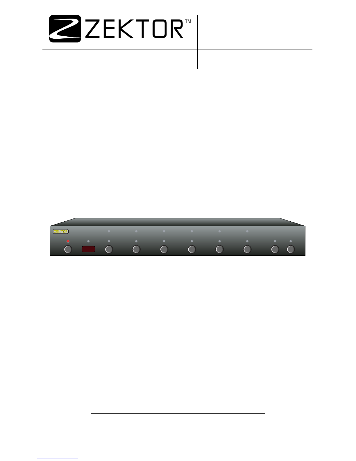
Front panel LED sequencing while learning
During the learning process, as each button of the remote is
pres sed, th e fro nt p ane l LED s wil l seq uen ce. At a ny giv en t i me , th e
LED that is slowly flashing, indicates the function the HDMI5 is cur-
rently waiting to learn. The sequence is:
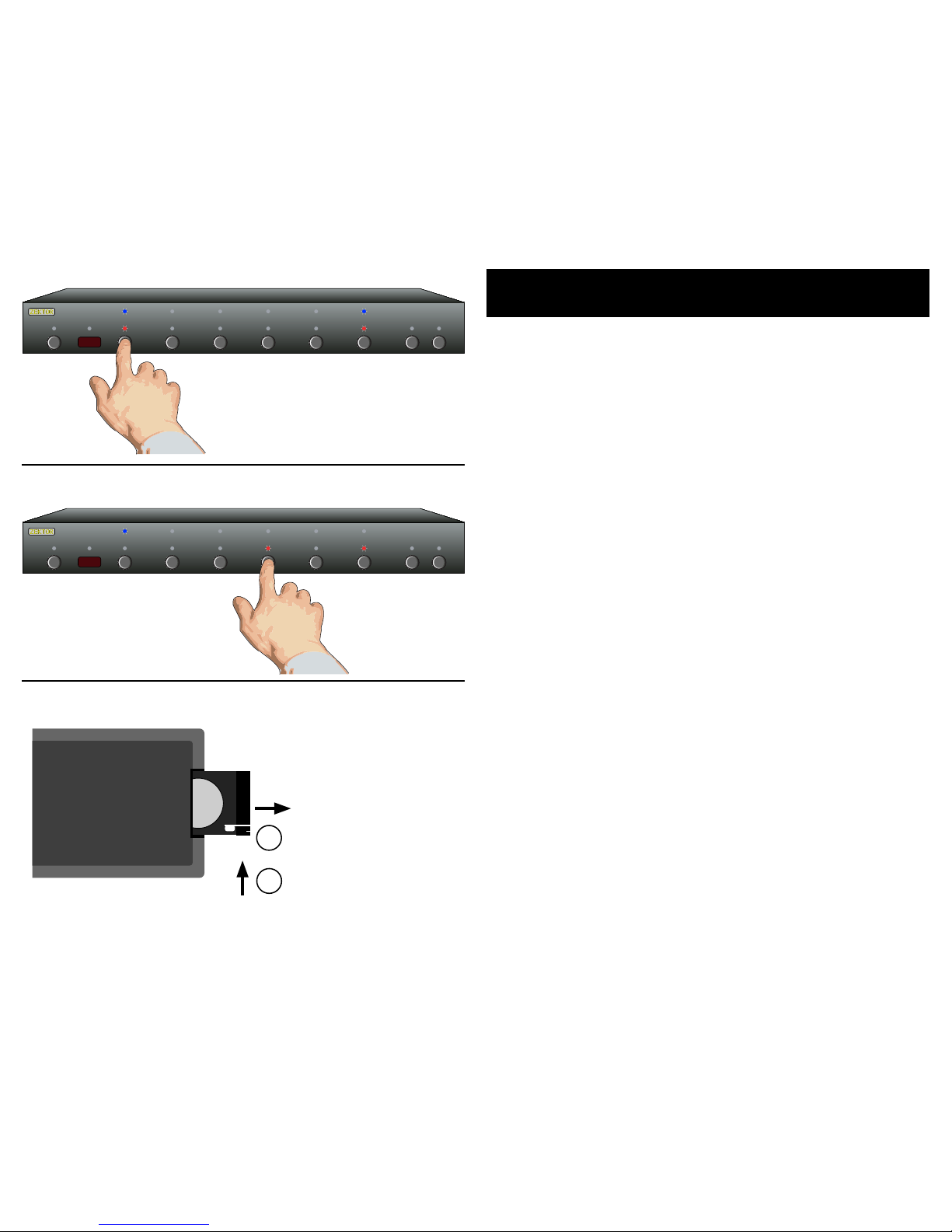
Standby LED Wait ing for Powe r Togg le IR c od e.
'1 ' - Red L ED Wai t in g fo r t he ' 1 ' IR c ode.
'2 ' - Red L ED Wai t in g fo r t he ' 2 ' IR c ode.
'3 ' - Red L ED Wai t in g fo r t he ' 3 ' IR c ode.
'4 ' - Red L ED Wai t in g fo r t he ' 4 ' IR c ode.
'5 ' - Red L ED Wai t in g fo r t he ' 5 ' IR c ode.
'SEL' Red LED Wa i ti n g fo r 'S E L' IR code.
'A1' L ED Wa iti ng for 'A1 ' IR code.
'A2' L ED Wa iti ng for 'A2 ' IR code.
If the LEDs do not sequence, and the IR LED does not flash, when a
button is pressed on the remote, then the HDMI5 does not recognize
th e IR co de b e in g s en t. Mak e sure th e re mot e' s b at ter ies a re f re sh.
The HD MI5 w ill w or k w ith m ost rem ote s, h owev er t h er e are a fe w
exceptions. Some technical reasons for not working with some re-
mo te s a re : T he r emo te m ay be u sin g a car rie r fre qu e nc y ou ts i de t h e
ra ng e o f th e H DM I 5 (3 4 KH z t o 42K H z), o r it may be u sin g one o f the
few protocols the HDMI5 does not understand, like the Philip's RC5
an d RC6 p ro tocol s.
If th e HDM I5 do es no t lea rn th e re mot e co des y ou a re us ing, y ou
wi ll have to us e ano the r re mot e, o r in th e cas e of us ing a u niver sal
remo te, yo u'l l have t o pic k a dif fe re nt ma nuf actu re r's cod e.
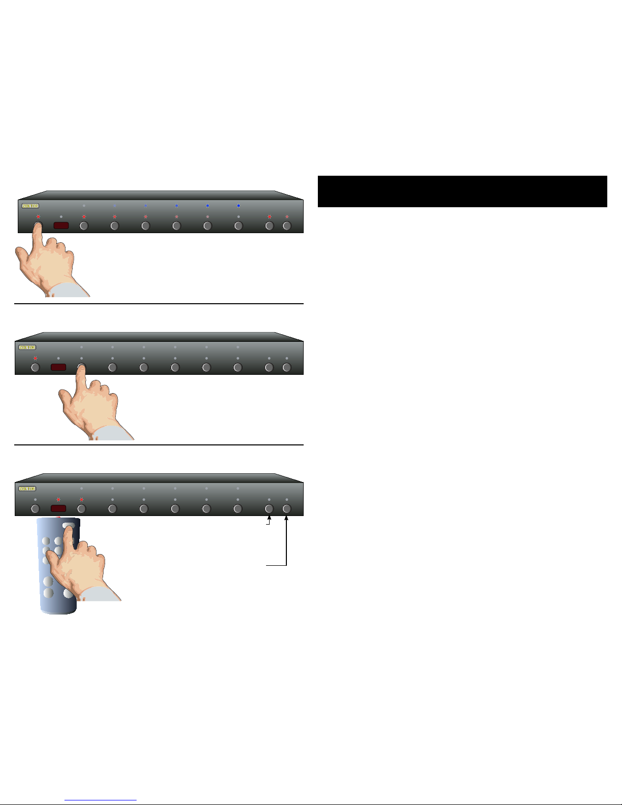
Skipping or Deleting IR codes
Du rin g the I R lea r ni n g pr ocess y ou c a n ch o os e to de let e th e c ur ren t
co de ( d is a bl e I R for th at fu ncti on) o r sk ip t h e cu r re nt code ( lea ve i t
unchanged) by pressing the 'A1' or 'A2 buttons:
'A1' Disable IR for current function.
'A2' S k i p cu r re nt c ode, le av e it un cha nge d.
The IR LED will flash...
...and the LEDs will sequence each time a
remote control button is pressed if the IR
code is compatible with the HDMI5.