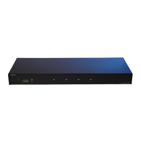
Zektor MAS7.1 User manual

1 2 3 S1 S2 S3 SYNC
Rev 2 07/17/2007
Multichannel Audio / HDMI Switch
MAS7.1
Home Theater Solutions

ii MAS7.1 Component Video Switch
1MAS7.1 Component Video Switch
Thank you for your purchase of the MAS7.1 Multichannel Audio and
HDMI Switch.
Every care has been taken to assure you of a successful installation
and subsequent operation of your new MAS7.1 video switch, however
should s o met h ing g o w ro n g, a nd wa r ran t y rep air work is n e ede d, we
re que s t tha t you h old on t o the o r igi n al pa c k agi n g mat eria ls.
Pl ease t ake th is tim e to ve rify t he co nte nts of t he MA S7.1 b ox .
The following should be included:
MAS7.1
Remote Control (ZRM1)
Power Supply Module
Th is Us er ’s M a nua l
If anything is missing please get in touch with us as soon as possible
so t h at we can co rre c t the si tuat ion.
1.
2.
3.
4.
What’s Inside
Contents
What’s Inside ..................................... 1
An Overview of the MAS7.1 ................ 3
Rear Panel Connectors....................... 5
Easy, Simple, Instructions! ................. 7
Using a Different Remote ................. 11
More Remote Options ...................... 13
Learning New Discrete IR Codes ....... 15
Controlling the Front Panel Lights ... 17
Adjusting the Front Panel Intensity .. 19
Setting the Initial Power On State .... 21
Control Functions ............................ 23
Changing Switching Delays.............. 25
Primary / Secondary Mapping.......... 27
Resetting to Factory Defaults........... 29
RS-232 Port ..................................... 30
K.I.S.S.™ (Keep It Simple Serial!™) .... 31
12V On / Off Control ........................ 32
Rear Panel IR Control....................... 33
IR Code Format ................................ 34
IR Codes .......................................... 35
Features .......................................... 36
Specifications.................................. 37
Warranty Policy ............................... 38
Contact Information ........................ 39

2MAS7.1 Component Video Switch
3MAS7.1 Component Video Switch
Front Panel Controls:
Pow er to ggl e b utt on.
Primary switch buttons.
Secondary switch buttons.
To g gle t h e SYN C LED. ( Syn c hro niz es the Pri m ar y and Se c -
ondary switches when lit).
e Dual Switch Design of the MAS7.1
With the SYNC LED lit, the MAS7.1 is simply a Multi-channel 7.1 Au-
dio/Digital Audio/HDMI switch. Pressing either '1'-'3' or 'S1'-'S3' will
select between the three inputs.
Wh en the S YNC L E D is un l it, t h e MA S 7.1 o p era tes a s t wo i n dep e n-
dent switches. A Primary switch (buttons '1'-'3') and a Secondary
switch (buttons 'S1'-'S3). Or you can think of the Secondary switch
as a v er y easy t o use a u dio b rea k a way fea tur e.
When the SYNC LED is off, pressing a Primary button ('1'-'3'), will
switch only the 5.1 Multi-channel audio paths (LF,RF,SUB,CEN,LR
& RR), while pressing a Secondary button ('S1'-'S3) will switch the
St ere o Au d io pa t hs (L & R ) , the D i gi t al au d io, and t h e HDM I s ign al.
However this default behavior can be easily changed.
For i n sta n ce if you would p refer t h e Pr i mar y sw i tch to co ntrol all
7.1 Analog Audio channels, while allowing the Secondary switch to
control the remaining channels, this is easily done.
The Primary and Secondary switches are easily configured to switch
any combination of the 5.1 Analog Audio, Stereo Analog Audio,
Digital Audio, and HDMI. See the section on "P ri m ar y / S ec on d ar y
Mappings".
Even the split between Multi-channel 5.1 and Stereo Analog Audio
channels can be changed by using a simple serial port command.
For more information on changing the Analog Audio split, download
th e "MAS7.1 Supplemental Manual".
1.
2.
3.
4.
1 2 3 S1 S2 S3 SYNC
Front Panel
An Overview of the MAS7.1
1 2 3 4

4MAS7.1 Component Video Switch
5MAS7.1 Component Video Switch
IR-IN
RS232
1 2 3 OUT
9VDC
HDMI 1 HDMI 2 HDMI 3 HDMI OUT
LF SUB LR L
1
RF CEN RR R
LF SUB LR L
2
RF CEN RR R
LF SUB LR L
3
RF CEN RR R
LF SUB LR L
OUT
RF CEN RR R
1 2
3 OUT
Rear Panel Connections
1 3
7 8 9 10
4
Rear Panel Connectors
Rear Panel Connectors:
Multi-channel (5.1) Audio Inputs.
Multi-channel (5.1) Audio Outputs.
Coax (S/PDIF) Digital Audio Inputs and Output.
HDMI Inputs and Output.
St ere o Au d io Inp u ts.
Stereo Audio Outputs.
Optical (TOSlink) Digital Audio Inputs and Output.
Hardwired IR-Jack input.
RS - 232 Cont rol Por t.
Power Supply Connection (Center connection is '+').
MAS7.1 Connections
The Multi-channel 5.1 Audio Inputs and Outputs can be switched
separately from the Stereo Audio Inputs and Outputs. (S e e : A n O ver -
view of the MAS7.1)
All Coax and Optical Digital Audio inputs are automatically convert-
ed, and you can use both the Coax and Optical Digital Audio outputs
at t he sam e time t o drive two d iffere nt de vice s.
1.
2.
3.
4.
5.
6.
7.
8.
9.
10.
5
2
6

6MAS7.1 Component Video Switch
7MAS7.1 Component Video Switch
Initial Setup...
Make analog audio, digital audio, and HDMI connections as
required by your particular setup.
If us i ng a PC ( o r oth e r ser i al co ntrolle r), co nne c t i t to th e
RS-232 port using a standard PC serial cable.
Hardwired IR control is also available using the IR-IN jack.
Pl ug the p owe r mod u le in to th e MAS 7 .1, a n d plu g t he mo d-
ul e i nto a s tan d ard A .C. w all rece p tac l e. The st a ndb y LED
wi l l lig ht up.
Selecting an Input...
To s w itc h betw een a ny of t h e thr ee in p uts , sim p ly pr ess t h e
button for the desired input. If the MAS7.1 is in the standby
mo d e, i t w ill t u rn on . The MAS7. 1 will t hen sw itc h to th e s e -
lected input, and the associated LEDs will light to indicate
this.
To p l ace t he MA S7.1 b ack in to th e stan dby m ode, pre ss and
release the Power Toggle button. The channel LEDs will all
go b l ank , an d the s t and by LED w ill li ght u p. Pre ss th e Powe r
Toggle button again to re-select the previously selected
input.
Synchronizing Primary and Secondary Switches...
When the SYNC LED is lit, the primary and secondary selec-
ti o ns wi l l swi tch at t he sa m e tim e. To all ow th e p rima r y a n d
secondary selections to be switched independently, press
th e S YNC b utton to t oggl e the SY NC LE D.
By default, the primary switch controls the 5.1 audio
settings.
By de faul t, the s eco n dar y sw i tch cont rol s the L & R stereo
channels, the digital audio channel, and the HDMI channel.
You can change the default behavior. The channels con-
trolled by the primary and secondary switches are configu-
rable and described later in this manual. See the section on
"Primary / Secondary Mappings".
For m o re i n fo r mat ion on u sing t he Pr imar y an d S eco ndar y
buttons see the section: "An O ver vi ew of th e MAS7 .1".
•
•
•
•
•
•
•
•
•
•
•
Selecting an Input: Press numbered buttons to select an input.
1 2 3 S1 S2 S3 SYNC
Easy, Simple, Instructions!
1 2 3 S1 S2 S3 SYNC
Synchronizing Primary and Secondary: Press SYNC to toggle.
When the SYNC LED
is lit, the primary and
secondary selections
are synchronized.

8MAS7.1 Component Video Switch
9MAS7.1 Component Video Switch
Instructions (Cont'd)
Installing the Remote Control's Battery
Or i ent t h e re m ote s o the you are look i n g a the b a cks i de
(buttons facing away from you).
Slide the battery holder out by pressing the small tab on
th e l eft, t owa rds t he ce nte r, w h ile p u lli n g dow nw a rd o n t he
holder.
Orient the battery with the positive terminal (+) up (as
illustrated).
Slide the battery holder back in place, until it clicks.
Using the supplied Remote Control
Use the section of the remote controlled labeled: MAS7
for co ntrolli ng the MAS7 .1. ( The oth er sec t ions a re us ed to
control other Zektor products.)
Each button on the remote functions the same as the front
panel switch with the same name.
•
•
•
•
•
•
1 2 3 S1 S2 S3 SYNC
1
5
2 3 4
1 2 3
1 2 3
1 2 3
S1 S2 S3
A1 A2
SYN
SEL
4
HDVI5/HDMI5
MAS7
CVS4
SAS6x2
Using the supplied Remote Control
Use the remote controller buttons in the section la-
beled: MAS7. (The other sections control other Zektor
products.)
Each button on the remote corresponds to the same
button on the MAS7.1's front panel.
Installing the Remote Control's Battery
CR2025
3V
+
To open: Press small tab
towards center...
1
2
While pressing tab, pull downward.

10 MAS7.1 Component Video Switch
11MAS7.1 Component Video Switch
Using a Different Remote
Th e MAS 7.1 feat ure s Zek tor ’s E xcl usive Intelli gent -IR ™ , and w i th ve r y
few excep tion s can be s et up to u se any re mote you c a n poi nt at it !
Th is is us eful i f you h ave more than o ne MA S7.1 i n the sa me ro om.
Pick a new remote
St a r t by pic k i ng a new remo te yo u’d lik e to us e w ith t h e
MAS7.1.
If yo u pla n o n usi n g a uni ver s al re mot e, s t ar t by se t tin g
it u p a s a re m ote for a T V o r VCR th at yo u don ' t o wn. ( Fo r
in s tan ce if you don’t ow n a S ony TV, setu p you r univers al
re mot e to co ntr ol a Sony T V. )
Step 1: Put the MAS7.1 into the Setup Mode
Th e MAS 7.1 is p laced into the s etup m ode by p re s sin g a nd
holding the Power button for about 4 seconds.
Step 2: Select the Intelligent-IR™ Learn Mode
Sel ec t the I n tel l ige nt- I R™ Learn M o de by p res s ing ‘1’.
Once the ‘1’ button is pressed, the standby LED will flash
sl owe r and al l the ot her LE Ds wil l turn o ff. The MA S7. 1 i s
no w wai t ing for ne w IR co d es to b e sent f ro m you r rem o te
co ntr ol.
Step 3: Teach the MAS7.1 your new remote control codes
On y our r emo te co ntrol, p res s the foll owin g butt ons, in th e
following order:
Power 1 2 3 4 5 6 0
The front panel LED's will sequence as each button is
pressed, and the IR LED will flash for each button -- if not,
see the following section on "More Remote Options".
Th at ’s it! The MAS7. 1 will retu r n to th e state it wa s in be for e
se t up, and w ill no w wo r k with your n ew re mote!
e new control buttons on your remote are...
Power To ggle s the MAS7. 1’s po wer.
1 - 3 Selects inputs 1 through 3.
4 - 6 Selects inputs S1 through S3.
0To g gle s t he SY NC LE D.
No te: All remot e co ntrol co des ar e save d i n non - vo lat i le
memory and will not be lost during a power failure.
•
•
•
•
•
•
•
•
1 2 3 S1 S2 S3 SYNC
Step 1: Put the MAS7.1 into the Setup Mode
Press and hold the Power Button for 4 secs.
The front panel LEDs will start to blink
wildly... (You’ll know it when it happens!)
Step 2: Press the ‘1’ button for Intelligent-IR™ learning
1 2 3 S1 S2 S3 SYNC
Step 3: Teach the MAS7.1 its new IR codes
1 2 3 S1 S2 S3 SYNC
1 2 3
4 5 6
7 8 9
0
+ +
_ _
POWER
VOL CH
Press the following sequence of buttons on
your remote control:
Power 1 2 3 4 5 6 0
That’s it! The MAS7.1 now operates with
your new remote control!
Once the 1 button is pressed, the
standby LED will flash slower, and
all the other LEDs will turn off.

12 MAS7.1 Component Video Switch
13MAS7.1 Component Video Switch
1 2 3 S1 S2 S3 SYNC
1 2 3
4 5 6
7 8 9
0
+ +
_ _
POWER
VOL CH
More Remote Options
Front panel LED sequencing while learning
During the learning process, as each button of the remote is
pr ess e d, t h e fro nt pa nel LE Ds wil l sequ ence. At a ny g ive n tim e, th e
LED that is slowly flashing, indicates the function the MAS7.1 is cur-
rently waiting to learn. The sequence is:
Standby LED Wai ting for Power To ggl e I R cod e.
'1 ' - L ED Wai ting for th e '1' IR c ode.
'2 ' - L ED Wai ting for th e '2' IR c ode.
'3 ' - L ED Wai ting for th e '3' IR c ode.
'S 1 ' - LED Wai ting for th e 'S1' I R cod e.
'S 2 ' - LED Wai ting for th e 'S2' I R cod e.
'S 3 ' - LED Wai ting for th e 'S3' I R cod e.
'S YN C ' L ED Wai ting for 'S YNC ' IR co d e.
If the LEDs do not sequence, and the IR LED does not flash, when a
bu t ton i s pre ssed o n the remot e, t hen th e MAS 7.1 do es not reco g-
ni ze the I R cod e bein g sent . M ake s u re t h e re m ote 's bat ter ies are
fresh.
Th e MAS 7.1 wi ll wo rk wit h most remo tes , however the re are a fe w
exceptions. Some technical reasons for not working with some re-
mo tes are: The r emo te may be usi ng a car r ier frequ ency ou t sid e t he
ra nge of t he MA S7.1 ( 34KH z t o 42K H z ), or i t m ay be u sing o ne of th e
few protocols the MAS7.1 does not understand, like the Philip's RC5
an d R C6 pr oto col s.
If th e MAS 7 .1 do e s not l e arn th e rem ote c ode s you a re us i ng, you
wi l l have to u se ano ther remo te, o r in th e c ase o f u sin g a u niv ers a l
re mot e, y ou' l l have to p i ck a di f fe ren t man u fac tu re r 's co de.
Skipping or Deleting IR codes
Du r ing th e IR lea r nin g p ro ces s you c a n cho o se to d elet e the c u rre nt
co de (di sabl e IR fo r tha t func t i on) o r s k ip the c urre nt co de (l e ave it
unchanged) by pressing the 'S2' or 'S3' buttons:
'S2' Disable IR for current function.
'S3' Sk ip c urrent code, leave it u ncha nged.
The IR LED will flash...
...and the LEDs will sequence each time a
remote control button is pressed if the IR
code is compatible with the MAS7.1.
1 2 3 S1 S2 S3 SYNC
1 2 3
4 5 6
7 8 9
0
+ +
_ _
POWER
VOL CH
Disable current IR code
Front panel LED sequencing while learning
Skipping or Deleting IR codes
Skip current code
(Leave IR unchanged)

14 MAS7.1 Component Video Switch
15MAS7.1 Component Video Switch
Learning New Discrete IR Codes
Th e MAS 7.1 al low s dis c re te IR co ntrol over a ll of it 's fun c t ion s. Thes e
co des ca n also b e rep rog ram med to use any re mote, as d escr i bed
he re.
Pick a remote
St a r t by pic k i ng the remo te yo u’d lik e to us e w ith t h e
MAS7.1. (Unused buttons on the supplied ZRM1 remote will
work just fine!)
Step 1: Put the MAS7.1 into the Setup Mode
Th e MAS 7.1 is p laced into the s etup m ode by p re s sin g a nd
holding the Power button for about 4 seconds.
Step 2: Select the Intelligent-IR™ Learn Mode
Discrete IR learning is selected by pressing the '2' button.
Once the '2' button is pressed, the standby LED will flash
sl owe r and al l the ot her LE Ds wil l turn o ff. The MA S7. 1 i s
no w wai t ing for ne w IR co d es to b e sent f ro m you r rem o te
co ntr ol.
Step 3: Teach the MAS7.1 your new discrete IR control codes
On y our r emo te co ntrol, p res s the bu tto n s yo u 'd l i ke to u se
as d i scr ete I R cod e s, i n the followin g ord er:
Power O n - Turn s O n Power
Power O f f - Turn s O f f Powe r
Seq uence Pr i. - Sequence primary inputs
Seq uence Sec . - Sequence secondary inputs
Sync O n - Turn o n S YN C L ED
Sync O f f - Turn o f f SYN C LED
Br eak away Vi d eo - S e ts vid eo breakaw ay m o de
Th e new codes a re le arne d i n the a b ove ord er, for i nsta nce
th e f irs t b utt on yo u pre ss, o n the remote, w ill be u se as th e
ne w d isc ret e "Pow er On ", th e s eco nd but ton p res s ed wi l l be
us e d as th e n ew "Power O ff ", etc.
Th e 'S2' c an be press ed to d isab le the c urre nt IR c ode .
Th e 'S3' c an be press ed to s k i p the cu r re nt IR co de, leav ing
it unchanged.
No te: All remot e co ntrol co des ar e save d i n non - vo lat i le
memory and will not be lost during a power failure.
•
•
•
•
•
•
•
•
1 2 3 S1 S2 S3 SYNC
Step 1: Put the MAS7.1 into the Setup Mode
Press and hold the Power Button for 4 secs.
The front panel LEDs will start to blink wildly.
Step 2: Press the '2' button for Intelligent-IR™ learning
1 2 3 S1 S2 S3 SYNC
Step 3: Teach the MAS7.1 its new IR codes
1 2 3 S1 S2 S3 SYNC
1 2 3
4 5 6
7 8 9
0
+ +
_ _
POWER
VOL CH
Press the buttons on
your remote, that you
want to use as the
new discrete IR codes,
in the order given in
"Step 3" of the text.
Once the 2 button is pressed, the
MAS7.1 will be ready to learn new
discrete IR codes starting with
"Discrete Power On".
Skip current IR
code (leave it
unchanged)
Disable current
IR code and
skip to next

16 MAS7.1 Component Video Switch
17MAS7.1 Component Video Switch
Controlling the Front Panel Lights
There are four different front panel lighting modes available on the
MAS7.1. They are:
Front panel lights automatically fade from bright to dim
af t er 4 sec ond s o f ina c t ivi t y.
Fro nt pa n el li g hts a re al way s at th e brig ht level.
Fro nt pa n el li g hts a re al way s at th e dim le vel.
Fro nt pa n el li g hts a re tu r ned o f f.
Note: The intensities of the both the bright and dim levels can be
adjusted as well. This is explained on the next page.
To change the front panel lighting mode...
Step 1: Enter the Setup Mode
Th e MAS 7.1 is p laced into the s etup m ode by p re s sin g a nd
holding the Power button for about 4 seconds.
Step 2: Select the Light Mode option
Press the ‘3’ button to select the “Lighting Mode” option.
The front panel selection LEDs now indicate the currently
selected light mode as follows:
If th e ‘1’ LED is li t, the n fro nt pa n el li g hts a re al ways off.
If th e ‘2’ LED is li t, the n fro nt pa n el is a l ways di m .
If th e ‘3’ LED is li t, the n fro nt pa n el is a l ways br i ght .
If the ‘S1’ LED is lit, then front panel lights auto-fade from
br i ght t o dim af t er 4 se cond s of ina c tivi t y.
Step 3: Choose a new light mode
Ch o ose a n e w lig ht co ntrol mod e by pr ess i ng th e b utt on as-
sociated with the desired operating mode.
Pres s the Power B u tto n to sa ve t h e new m o de an d ret u rn
to n orma l o per ati o ns, o r co n tin u e on to t he ne x t p age to
adjust the DIM a BRIGHT levels.
Note: The lighting mode setting is saved in non-volatile mem-
or y an d is not a ffe c ted by a power f a ilu re.
•
•
•
•
•
•
•
•
•
1 2 3 S1 S2 S3 SYNC
Step 1: Place the MAS7.1 into the Setup Mode
Press and hold the Power Button until the
display goes wild. (About 4 seconds.)
Step 2: Select “Light Mode”option
1 2 3 S1 S2 S3 SYNC
After ‘3’ is pressed, the standby
LED continues to flash, and the
front panel will display the cur-
rent Light Mode settings.
Step 3: Choose a new lighting mode
1 2 3 S1 S2 S3 SYNC
Auto-Fade
Always Bright
Always Dim
Always Off
Exit Setup Mode

18 MAS7.1 Component Video Switch
19MAS7.1 Component Video Switch
1 2 3 S1 S2 S3 SYNC
Step 4: Select between Bright and Dim settings: Use SEL button.
Step 5: Adjust Front Intensities.
1 2 3 S1 S2 S3 SYNC
Use S2 and S3 to dim and brighten LEDs
S2 = Dim LEDs.
S3 = Brighten LEDs.
Adjusting the Front Panel Intensity
Continued from previous page...
If yo u have no t a lre ady d o ne so, pe r form St eps 1 a n d 2 on th e p re v i-
ous page.
Step 4: Toggling between Bright and Dim Settings
The 'SYNC' LED indicates the front panel intensity settings:
If lit, then the BRIGHT level is being adjusted.
If off, then the DIM level is being adjusted.
Us e the 'S YNC ' butt on to t ogg l e bet w een b r igh t a nd di m
settings.
Step 5: Adjust Front Panel Intensities
Us e the ‘S2’ butto n to de cre ase th e int ensi t y of the f ron t
panel lights.
Us e the ‘S3’ butto n to in cre ase th e int ensi t y of the f ron t
panel lights.
Us e the 'S YNC ' butt on to t ogg l e bet w een t h e bri g ht an d
dim settings.
You cannot make the DIM level brighter than the BRIGHT
level, and you cannot make the BRIGHT level dimmer than
th e D IM le vel .
Step 6: Use the Power Button to Exit
Once the front panel intensities are acceptable, press the
Pow er bu t to n to save th e n ew se t tin g s and e x it th e s etu p
mode.
Note: The new intensity settings are saved in non-volatile
me m or y and a re no t a ffe c ted b y a power f a ilu re.
•
•
•
•
•
•
•
Use the SYNC button to toggle between
the BRIGHT and DIM settings.
1 2 3 S1 S2 S3 SYNC
Step 6: Use the Power Button to Exit.
When things look good, press the
power button to exit the setup mode.

20 MAS7.1 Component Video Switch
21MAS7.1 Component Video Switch
1 2 3 S1 S2 S3 SYNC
Step 1: Set the MAS7.1 to the preferred initial power on state
Setup the MAS7.1 to the initial
power on state you’d prefer. In
this case we want the MAS7.1
to turn on and switch to Input
3 when first plugged in.
Step 2: Save the new initial power on state
1 2 3 S1 S2 S3 SYNC
Start by pressing and
holding the Power
button...
Setting the Initial Power On State
As long as the MAS7.1 is plugged in, it will remember the previously
se l ecte d inpu t in sta ndby m ode . Whe n pow ere d up by p res sing t he
Power button, it will return to that previously selected channel.
Ho wever, if po we r i s re m oved (for in s tan ce a plu g stri p u sed t o
power the MAS7.1 is turned off ), and then re-applied, the MAS7.1’s
default behavior is to enter into the standby mode.
It is possible to change the initial power on behavior of the MAS7.1.
To change the initial power on defaults...
Step 1: Setup the MAS7.1 to your preferred power on state
.
Us e the front p ane l b utt ons to s etu p t he MA S7. 1 to th e o p -
er ati n g set t ing s you’d l ike a t i nit i al po we r u p.
Step 2: Save the new initial power on state.
Firs t pre ss and h old th e Powe r but ton.
Wh ile co nti nuin g to ho l d the Power b utto n, pr ess a n d hol d
the ‘1’ button.
After holding both buttons for about ‘4’ seconds, the dis-
play will blink indicating the new power on defaults have
be e n acc ept ed.
Test the new initial power on state
You can test the new defaults by either disconnecting the
po wer s uppl y fro m the ba ck of th e MAS 7.1 or by unp lug-
gi ng the p ower sup ply from th e wall.
Rec onn e c t power. The MA S7.1 w ill powe r up into yo ur new
po wer o n defa ult st ate.
•
1.
2.
3.
•
•
12...while continuing to hold the Power
button, press and hold the‘1’ button.
After about 4 seconds, the display will
flash indicating the new Power On
Default state has been accepted.
3

22 MAS7.1 Component Video Switch
23MAS7.1 Component Video Switch
Control Functions
If yo u are u sin g t he re ar pa n el IR j a ck, yo u migh t wan t to di sabl e the
IR s e nso r s to prevent u s e of th e rem o te co ntrol.
Or if you have a household with young curious fingers that likes
playing with buttons, you also have the capability of disabling the
front panel switches and only operating the MAS7.1 with a remote.
To enable / disable the front panel switches, and other control
functions...
Step 1: Enter the Setup Mode
Th e MAS 7.1 is p laced into the s etup m ode by p re s sin g a nd
holding the Power button for about 4 seconds.
Step 2: Enter the Enable / Disable control state
While in the setup mode, press 'S1' to enter the Enable/Dis-
ab l e con tro l sta te. The c u rre nt st atus w ill be d ispl aye d us-
ing the front panel LEDs.
A lit LED indicates an option is enabled, and an unlit LED
indicates disabled.
Step 3: Enable or Disable control functions
Use '1' to enable/disable the IR Sensor hardware.
Use '2' to enable/disable the IR Jack hardware.
Use '3' to enable/disable the front panel buttons.
Use 'S1' to enable/disable IR control.
Use 'S2' to enable/disable 12V On/Off control.
No te 1: Th e I R Jac k and 12 V O n/O f f con tro l func t i ons a re mut u-
ally exclusive (They use the same jack!). Enabling 12V
On/ O ff co ntr ol wi l l dis a ble t h e IR Ja ck hardwa re. En-
abling IR Jack hardware will disable 12V On/Off control.
No te 2: Whe n disa blin g the IR J ack a n d IR Sen s or, th e h ard -
ware is disabled. Whereas 'IR Control' enables/disables
whether the MAS7.1 responds to IR signals received. If
th e I R Sens or or IR J ack a re ena bled, and ' IR Cont rol '
disabled, IR signals can still be read through the RS-232
port, while being ignored by the MAS7.1.
Note 3: Disabling the front panel buttons does not disable the
ab i lit y t o ent er th e S etup M odes.
•
•
•
•
•
•
•
•
Step 3: Enable or Disable control functions
1 2 3 S1 S2 S3 SYNC
Enable/Disable 12V Ctrl.
Enable/Disable IR Control
Enable/Disable Buttons
Enable/Disable IR Jack
Enable/Disable IR Sensor
Exit Setup Mode
1 2 3 S1 S2 S3 SYNC
Step 1: Place the MAS7.1 into the Setup Mode
Press and hold the Power Button until the
display goes wild. (About 4 seconds.)
Step 2: Enter the Enable / Disable control state
1 2 3 S1 S2 S3 SYNC
After ‘S1’ is pressed, the standby
LED continues to flash, and the
front panel will display the cur-
rent settings.

24 MAS7.1 Component Video Switch
25MAS7.1 Component Video Switch
Changing Switching Delays
The MAS7.1 allows adjusting the switching delay times, for Multi-
channel Audio, Stereo Audio, Digital Audio and HDMI, all indepen-
de nt of ea ch oth er.
To adjust the Audio / Video switching delays...
Step 1: Place the MAS7.1 into the Setup Mode
Th e MAS 7.1 is p laced into the s etup m ode by p re s sin g a nd
holding the Power button for about 4 seconds.
Step 2: Enter the Switching Delay Setup Mode
Pres s the 'S 2' but ton t o ent er th e Swit chi n g Del ay Set u p
Mod e.
Th e LEDs i ndic ate t he mute del ay, i f there are no LED s lit,
th e n the re is n o d ela y.
Wh en SYN C LED i s l it, t h en LE D s 1, 2 an d 3 i ndi c ate t he
cu r ren t HDM I d ela y, and S 1, S2 an d S3, in dica te th e Digital
Au dio m u te d e lay.
Wh en SYN C LED i s o ff, t h en LE D s 1, 2 an d 3 i ndic ate t he cur -
rent Multi-channel Audio delay, and S1, S2 and S3, indicate
th e S tereo Audi o d ela y.
Th e delay tim es are rep res ent ed by t h e num b er an d p osi -
ti o n of th e l it LE D s, a s fol low s:
No L E Ds li t = 0 se c d ela y.
• One left justified LED = 20ms delay.
•• Two lef t j u sti f ied L E Ds = 5 0 m s del ay.
••• Three left justified LEDs = 100ms delay.
•• Two r ight j usti fied L EDs = 2 0 0ms d e lay.
• On e r ight j ust i fie d L ED = 50 0ms d e lay.
Step 3: Adjust Switching Delay Times
The 'SYNC' button toggles between the HDMI/Digital Audio
delay settings and the Multi-channel/Stereo Audio delay
settings.
The '1' and 'S1' buttons decrease delay times, and the '3'
and 'S3' buttons increase delay times.
Pres s the Power b u tto n to sa ve n e w set t ing s a nd ex i t.
Note: The new settings are saved in non-volatile memory and
ar e not a f fe c t ed by a p ower fa i lur e.
•
•
•
•
•
•
•
•
•
1 2 3 S1 S2 S3 SYNC
Step 1: Place the MAS7.1 into the Setup Mode
Press and hold the Power Button until the
display goes wild. (About 4 seconds.)
Step 2: Enter the Switching Delay Setup Mode.
1 2 3 S1 S2 S3 SYNC
After pressing 'S2', the standby
LED continues to flash, and the
front panel will display the cur-
rent delay settings.
Step 3: Adjust Switching Delay Times
1 2 3 S1 S2 S3 SYNC
LED is lit when adjusting
HDMI/Digital Audio delays
LED is unlit when adjusting
Multi-channel and Stereo
Audio, delays
Exit
Decrease delay
Increase delay Increase delay
Decrease delay

26 MAS7.1 Component Video Switch
27MAS7.1 Component Video Switch
Primary / Secondary Mapping
The MAS7.1 can be configured as a single Multi-channel Audio /
Digital Audio / HDMI switch, or it can be used as two independent
switches, by simply pressing the SYNC button.
When the SYNC LED is lit, all channels of audio and HDMI signals
sw i tch a t the s a me ti m e, w h en th e S YN C L ED is o f f, the s i gn a l pat h s
can be switched independently of each other.
By default, when the SYNC LED is off, the Primary buttons (1-3) will
switch the 5.1 multi-channel audio paths, while the Secondary but-
tons (S1-S3) will switch the L & R stereo audio channels, the digital
audio channel, and the HDMI channel.
The following shows how to change this default behavior, allowing
yo u to as sign w hat eve r cha n nel s you 'd li k e to th e Pr i mar y / Sec ond-
a r y b ut to ns .
Step 1: Place the MAS7.1 into the Setup Mode
Th e MAS 7.1 is p laced into the s etup m ode by p re s sin g a nd
holding the Power button for about 4 seconds.
Step 2: Enter the Primary / Secondary Mapping Setup Mode
Pres s the 'S 3' but ton t o ent er th e Pri m ar y / S eco ndar y Ma p -
pi n g Setu p M ode .
Step 3: Select new Primary / Secondary Mappings
A li t L ED in d ica tes a c h ann e l is ma p ped t o the Prim a r y
switch, an unlit LED indicates it's mapped to the Secondary
switch.
The LEDs/Buttons 1,2,3 & S1 are used to map the Multi-
channel Audio, Stereo Audio, Digital Audio and HDMI,
respectively:
'1' - Multi-channel Audio (LF,RF,SUB,CEN,LR,RR)
'2 ' - St ere o Au d io (L , R)
'3' - Digital Audio (Optical and Coax)
'S 1 ' - H D MI
Pres s the Power b u tto n to sa ve n e w set t ing s a nd ex i t.
Note: The new settings are saved in non-volatile memory and
ar e not a f fe c t ed by a p ower fa i lur e.
•
•
•
•
•
1 2 3 S1 S2 S3 SYNC
Step 1: Place the MAS7.1 into the Setup Mode
Press and hold the Power Button until the
display goes wild. (About 4 seconds.)
Step 2: Enter the Primary / Secondary Mapping Setup Mode.
1 2 3 S1 S2 S3 SYNC
After pressing 'S3', the standby
LED continues to flash, and the
front panel will display the cur-
rent map settings.
Step 3: Change Primary / Secondary Mapping.
1 2 3 S1 S2 S3 SYNC
Exit
Multi-channel (LF, RF, SUB, CEN, LR, RR)
Stereo Audio (L & R)
Digital Audio (Optical & Coax)
HDMI
A lit LED indicates the channel is mapped to the primary buttons.
Otherwise channel is mapped to the secondary buttons.

28 MAS7.1 Component Video Switch
29MAS7.1 Component Video Switch
Step 1: Reset All Parameters to Factory Defaults
1 2 3 S1 S2 S3 SYNC
Start by pressing and
holding the Power
button...
12...while continuing to hold the Power
button, press and hold both the‘3’
and the ‘S1’ buttons.
After about 4 seconds, the display will flash
indicating all parameters have been restored
to their factory programmed values.
3
Resetting to Factory Defaults
If, for wha tever reaso n, yo u’d lik e to re set your MAS7. 1 back t o its
factory default condition, this is easily done...
Step 1: Reset All Parameters to Factory Defaults
Firs t pre ss and h old th e Powe r but ton
Wh ile co nti nuin g to ho l d the Power B utto n, pr ess a n d hol d
both the ‘3’ and ‘S1’ buttons.
After holding all buttons for about 4 seconds, the display
will flash indicating all parameters have been restored to
their factory programmed values.
Note: Resetting the MAS7.1 to its default value, resets every-
th i ng to t he sam e state it w as whe n it lef t t h e fac tor y!
This includes any learned IR codes and all timing infor-
mation, new switch mappings, etc.
Please be aware of this before issuing this command!
1.
2.
3.

30 MAS7.1 Component Video Switch
31MAS7.1 Component Video Switch
K.I.S.S.™ (Keep It Simple Serial!™)
Zektor’s exclusive K.I.S.S.™ (Keep It Simple Serial™) protocol was de-
signed by engineers who have been controlling RS-232 devices for
most of their careers and understand the pitfalls of a badly designed
pr oto col .
A few features of the K.I.S.S.™ protocol are:
A simple and logically consistent command structure.
Fully bi-directional operations and can be operated in both
a Master/Slave mode (only responds when spoken to), or
in an Asynchronous mode (state changes are sent as they
occur).
All commands and responses can optionally use a checksum
or a CRC-8 checkcode to insure reliable communications.
A co mman d will a lwa ys ge nerate a r esp o nse ! There are no
“ti meou t ” states as p ar t o f the p rot oco l. A ti m eou t w ill a l -
wa ys i n dic a te s o me typ e o f physi c al co nnec t i on er ror (l oose
cable, extreme noise, etc.).
Commands and responses have been designed for simple
parsing in any language.
Ea s y to te st us i ng a te rmin al, o r ter m inal e mula tio n s oft-
wa re. (Hype r t erm, S e cur eCR T, et c.)
A few features of the MAS7.1 command set are:
A full featured command set that goes far beyond simple
fr ont p anel c ont rol o peratio ns! Al low s full c ont rol ove r all
features of the MAS7.1.
All front panel functions supported.
Full notification of state changes.
Th e abil ity to d isab le the f ron t pan e l, a n d sti l l have front
panel button presses sent to the serial port.
High resolution control over all timing settings.
Th e abil ity to read a ll IR co des s e nt to t he MA S7. 1 by any
re mot e, e ven I R code s not us ed by t h e MA S 7.1 . Use th e
MA S7. 1 to add I R con tro l to any projec t !
Ma ny mor e fea t ure s, t o o num ero us to li st here. ..
For a full description of K.I.S.S.™ and a list of the commands sup-
ported by the MAS7.1, download the MAS7.1 supplemental manual
at :
www.zektor.com/MAS7.1/downloads.htm
•
•
•
•
•
•
•
•
•
•
•
•
•
Th e RS-2 3 2 on th e MAS 7 .1 is t h e sam e for m at as a P C-mo dem, a nd
uses the same type cable as a serial modem would, which is a stan-
da rd st raig ht th rou g h cab l e. D o n ot use a c able t hat i s m arke d as a
“Null Modem” cable.
Th e MAS 7.1 ca n also b e used w ith any US B to RS- 2 32 co nv ers i on
cable, these are all typically straight through cables.
The RS-232 port is a female type DE-9 connector (sometimes mistak-
en l y re fer red t o as a DB- 9 conn ecto r ) wit h t he fo llo win g p ino u t:
5 4 3 2 1
9 8 7 6
Pin definitions:
1 - No C o n ne c t 6 - No C o n ne c t
2 - TX 7 - No C o n ne c t
3 - RX 8 - No C o n ne c t
4 - No C o n ne c t 9 - No C o n ne c t
5 - GN D
The port settings used by the MAS7.1 are:
Baudrate: 9600
Data Bits: 8
Stop Bits: 1
Parity: NONE
The communications protocol used is Zektor’s exclusive K.I.S.S.™
(Keep It Simple Serial™) protocol.
RS-232 Port

32 MAS7.1 Component Video Switch
33MAS7.1 Component Video Switch
Rear Panel IR Control
The rear panel jack labeled "IR-IN" allows the MAS7.1 to be con-
trolled by hardwired IR controllers.
To enable/disable the rear panel IR jack, see the section entitled:
"Control Functions".
The IR signal can be either modulated or unmodulated with a modu-
lation frequency ranging from 30KHz to 500KHz.
30KHz to 500KHz
3V to 15V
0V
MODULATED SIGNAL
UNMODULATED SIGNAL
3V to 15V
0V
And uses a standard 1/8" (3.5mm) mini-plug:
SLEEVE
TIP
The voltage level is bi-directional and fully opto-isolated. It doesn't
ma tte r w hic h way y ou co nne c t your volt age so urc e acr oss t h e tip
and sleeve of the connector. Neither side of the IR-jack is grounded,
and either the tip or the sleeve can be connected to ground without
the possibility of ground loops.
Th e signal volta ge can r ang e f ro m + 3V to + 15V or f rom - 3V to - 1 5V.
Th e IR jac k recogn ize s the sa me IR co des a s t he fr ont p anel I R sen-
so r. If th e MAS 7.1 is t augh t new codes, the se new c ode s w ill b e com e
th e n ew co des reco gni zed by t he IR j a ck.
Note: The IR control jack option is mutually exclusive with 12V
On/Off control option (they use the same jack!).Only one
of these options can be enabled at a time.
12V On / Off Control
The rear panel jack labeled "IR-IN", when not being used as an IR
Ja c k , can al low t he MA S7.1 t o be tu r ned on a nd off u sing a 1 2V co n -
trol voltage.
To enable/disable the 12V On/Off control functions, see the section
entitled: "Control Functions".
By enabling the 12V On/Off control option, the MAS7.1 will turn
itself on whenever the voltage going into the IR-IN jack goes from
LOW to HIGH, and it will turn itself off whenever the voltage goes
fr om HI G H to LO W.
The MAS7.1 only looks at transitions on the IR-IN jack. For instance if
it d e tec t s a LOW to H IGH t rans itio n it wil l turn i t sel f o n. The us er can
th e n use t h e power sw itc h to tu r n off th e MAS 7.1. A f ter w hich t he
voltage on the IR-IN jack must go from HIGH to LOW and then back
to H IGH, t o onc e aga i n tur n o n the MAS7. 1.
The voltage level is bi-directional and fully opto-isolated. It doesn't
ma tte r w hic h way y ou co nne c t your volt age so urc e acr oss t h e tip
and sleeve of the connector. Neither side of the IR-jack is grounded,
and either the tip or the sleeve can be connected to ground without
the possibility of ground loops.
A HI G H lev el is a ny volta ge from +3V t o +15 V, or a ny volta ge from
-3 V to -15 V.
A LO W l eve l is any vo ltag e between -0 .2V an d +0.2 V.
All levels between these two levels is undefined.
SLEEVE
TIP
Note: The 12V On/Off control option is mutually exclusive with
IR Control jack option (they use the same jack!).Only one
of these options can be enabled at a time.

34 MAS7.1 Component Video Switch
35MAS7.1 Component Video Switch
IR Code Format
Th e defa ult IR code s used b y the M AS7 . 1 are 3 2 bit s l ong, bas ed on
the NEC transmission protocol and use a carrier frequency of 38KHz.
Ty pica l IR Co de. E xamp le Co de = 807D08F7 (hex):
108 mS 108 mS
8 0 7 D 0 8 F 7
Stop Bit
Leader Data Bits Repeat Code
A magnified view of the Leader and first three data bits:
9 mS 4.5 mS 2.25 mS
1 Bit 0 Bit
1.125 mS
0.56 mS
A magnified view of the Repeat Code (sent when key is held down):
9 mS 2.25 mS
0.56 mS
.
The following are the factory default codes used by the MAS7.1:
Handheld
Remote Codes Function
807D8877 Powe r Togg l e
807D40BF '1' Button
807D609F '2 ' B utt on
807D50AF '3 ' B utt on
807D48B7 'S1' Button
807D6897 'S2' Button
807D58A7 'S3' Button
807D7887 'SYNC' Button
Discrete Codes Function
807DD42B Disc ret e Power On
807DE41B Disc ret e Power O ff
807DF40B Seq uenc e Pr i mar y Inp u ts
807D06F9 Sequence Secondary Inputs
807D16E9 SY NC On
807D26D9 SY NC O ff
These are the default codes of the MAS7.1, they can be easily
changed by teaching the MAS7.1 a new set of IR codes -- useful if
more than one MAS7.1 resides in the same room.
To change IR codes, see the sections: "Using a Different Remote" and
"Learning New Discrete IR Codes".
IR Codes

36 MAS7.1 Component Video Switch
37MAS7.1 Component Video Switch
Features
Analog Audio
Channels:
Gain:
Signal to Noise:
Dynamic Range:
Audio Frequency Response:
Video Frequency Response:
Crosstalk:
Digital Video Channels
Protocols:
DVI / HDMI Bandwidth:
DVI/HDMI Pixel Rate:
HDTV Resolutions:
HDCP:
HDMI Audio:
PC Resolutions:
Digital Audio Channels
Inputs:
Outputs:
Maximum Transfer Rate:
Digital Audio Modes:
Coax Input Level Range:
Coax Output Level:
Control
IR Sensor:
IR Jack:
12V Control:
Serial Port:
Power Requirements:
Voltage Requirements:
Optional International:
Adapter Power Supply:
Dimensions:
Warranty:
Eight Full Bandwidth (200MHz) Channels
0 dB (Passive)
90dB re +4dBu, 22KHz BW, unweighted
112dB re +26dBu, 22KHz BW, unweighted
0Hz-100KHz, +0/-0.05 dB
Bandwidth: 0Hz-200MHz, +0/-3 dB
Greater than 100dB, 20Hz-20KHz, worst case all channels
DVI 1.0, HDMI 1.0 through HDMI 1.3a
Supports Deep Color 36-bit color depth and resolutions up to
1080p @ 60Hz or 720p/1080i @ 120Hz
2.25GHz
225Mps
480p through 1080p, including 720p and 1080i
(All Single Link DVI / HDMI modes are supported)
All DVI and HDMI HDCP modes are supported
Fully supports all HDMI Audio modes
640x480p through 1920x1200p
(All Single Link PC resolutions supported)
3 Coax, 3 Optical, (Auto conversion between formats)
1 Coax (S/PDIF), 1 Optical (TOSLINK), (Simultaneous)
Optical 13.2Mb/S, Coax 50Mb/S
PCM, DD5.1, DTS, All digital audio modes supported
200mV - 7.0V (S/PDIF compliant and PC Soundcard Compatible)
500mV Nominal (S/PDIF Compliant)
Modulation Frequency: 34KHz-42KHz
3V to 15V any polarity, modulated or unmodulated
3V to 15V (any polarity) for ON, less than 0.2V for OFF
(IR jack is opto-isolated to prevent ground loops)
9600 Baud (8N1), USB Serial Cable Compatible
K.I.S.S.™ Protocol, Firmware Upgradable
Standby 2W, On 4.5W Typical
90-120VAC, 60Hz
90-264VAC, 47-63Hz
Wall Mount, 9V @ 500ma, U.L. Listed (Center connection is '+')
Rack Mountable, 17”W x 6.5”D x 1.75”H
Two Year Parts and Labor
Specifications:
Specifications
Features of the MAS7.1:
Fully passive analog audio switching. All analog audio switching
is done using gold-clad over silver-paladium relay contacts. There
are no active components in the audio paths, no capacitors, no
resistors, just a gold on gold relay contact.
More than just an Analog Audio switch, the MAS7.1 will also
switch Digital Audio (with auto-conversions between Coax and Op-
tical inputs) and HDMI. Separate ground planes are used for the
analog and digital paths to help eliminate cross talk between the
analog and digital signals.
Use the MAS7.1 as a Multi-channel 7.1 audio switch, or at the
press of button it can become two independent switches, where
each switch can be easily configured to independently switch
Multi-channel 5.1 audio, Stereo Audio, Digital Audio, and HDMI,
channels. It's the ultimate in audio/video breakaway!
Independently adjustable delay times for each signal type.
Unmatched control features. The MAS7.1 can be controlled using
front panel buttons, an IR remote, an opto-isolated hardwired IR
jack that accepts modulated, or unmodulated IR signals of any
polarity, an RS-232 port, and even a simple 12V On/Off voltage.
It can be taught to use a different remote control, allowing you
to have an unlimited number of MAS7.1's in the same room and
control them all separately. The RS-232 command set is one of
the easiest to use on the market and allows unprecedented control
over the MAS7.1's operations.
Adjustable front panel LED intensities. Eliminate the distraction of
glaring LEDs by having the front panel dim after a few seconds of
sitting idle. The LEDs can even be dimmed to "off".
Perfect for the professional home theater installer! The MAS7.1 is
rack mountable and comes in black or silver.
•
•
•
•
•
•
•
Table of contents
Other Zektor Switch manuals

Zektor
Zektor HDVI5 User manual

Zektor
Zektor ZEKTOR MAS3 User manual

Zektor
Zektor CVS4 Owner's manual

Zektor
Zektor HDS4.2 User manual

Zektor
Zektor CVS4 User manual

Zektor
Zektor HDMI5 User manual

Zektor
Zektor HDS4.1 User manual

Zektor
Zektor HDVI5 User manual

Zektor
Zektor HDMI5 User manual

Zektor
Zektor HDA604 User manual