Zektor HDS4.1 User manual

ZEKTOR
Home Theater Switches
Digital Video / Component Video / Multichannel Audio
Rev 2 02/22/2006
High Definition Component Video Switch
1 2 3 4
ZEKTOR
HDS4.1
All manuals and user guides at all-guides.com
all-guides.com

ii HDS4.1 Component Video Switch
1HDS4.1 Component Video Switch
Thank you for your purchase of your HDS4.1 High Definition Compo-
nent Video Switch.
Every care has been taken to assure you of a successful installation
and subsequent operations of your new HDS4.1 video switch, however
should something go wrong, and warranty repair wo r k i s n e e d e d, we
re q u e s t t h a t you hold on to the original pack a ging materials.
Pl e a s e t a k e t h i s t i m e t o verify the contents of the HDS4.1 box.
The following should be included:
HDS4.1
Power Supply Module
Th i s U s e r ’s Manual
If anything is missing please get in touch with us as soon as possible
so that w e c a n cor rec t t h e s i t u ation.
1.
2.
3.
What’s Inside
Contents
What’s Inside ..................................... 1
An Overview of the HDS4.1 ................ 3
Easy, Simple, Instructions! ................. 5
Three Simple Steps to a Remote! ........ 7
Controlling the Front Panel Lights ..... 9
Adjusting the Front Panel Intensity .. 11
Setting the Initial Power On State .... 13
Disabling Front Panel or Remote...... 15
Resetting to Factory Defaults........... 17
Specifications.................................. 19
Warranty Policy ............................... 20
Contact Information ........................ 21
All manuals and user guides at all-guides.com

2HDS4.1 Component Video Switch
3HDS4.1 Component Video Switch
1
2
3
4
5
6
1
2
3
4
5
Front Panel Controls:
Powe r I ndicato r. Lights up in standby m o d e .
Selection LEDs. Indicate currently selected inputs.
Input Selection Buttons.
Infrare d R emote S ensor Wi n d ow.
Infrare d R ece i v e d I n d i c a t o r. Flashes when IR is receive d.
Powe r To g g l e Butto n .
Rear Panel Connections:
Analog Inputs. Each input consists of six equivalent chan-
nels. The channels are colored and labeled for convenience,
however all six channels are of equivalent bandwidth and
functionality, and may be interchanged as desired.
Analog Outputs.
Digital Audio Inputs. Each input has an associated digital
audio channel with both a Coax and an Optical connection.
Only one of the two types of inputs can be ac t i ve at any
time. The HDS4.1 will auto-selec t b e t we e n t h e t wo t ypes of
signals. If a signal is supplied to both the Coax and Optical
inputs, t h e Coax signal is give n p r i o r ity.
DC Powe r J a c k Connec t o r. Plug in the supplied power
adapter into this jack.
Digital Audio Outputs. All digital audio inputs are automat-
ically converted to both Coax and Optical outputs. All three
outputs are available at all times, and are all individually
buffered to allow driving three different digital audio de-
vices simultaneously.
1.
2.
3.
4.
5.
6.
1.
2.
3.
4.
5.
1 2 3 4
ZEKTOR
R/V L/H C/V
Y/G Pb/B Pr/R
R/V L/H C/V
Y/G Pb/B Pr/R
R/V L/H C/V
Y/G Pb/B Pr/R
R/V L/H C/V
Y/G Pb/B Pr/R
R/V L/H C/V
Y/G Pb/B Pr/R
DIGITAL AUDIO
1 2 3 4 OUT
4 OUT OUT
1 2 3
9VDC
1 2 3 4 OUT
Front Panel
Rear Panel
An Overview of the HDS4.1
All manuals and user guides at all-guides.com

4HDS4.1 Component Video Switch
5HDS4.1 Component Video Switch
Step 1...
Use the analog input connections to switch component
video / composite video / analog audio or any combination
of the above signals to the HDS4.1’s analog output connec-
to r s. Use the digital audio connectors to switc h d i g i t a l a u -
dio signals, with full format conversion between the optical
and coax digital audio formats.
Plug the power module into the HDS4.1, and plug the mod-
ule int o a s t a n d a rd A.C. wall rece p t a c l e. The standby L E D
will light u p.
Step 2...
To s w i t c h b e t we e n a ny of the fo u r i n p u t s , s i m p l y p ress
the button for the desired input. If the HDS4.1 is in the
standby, it will turn on. The HDS4.1 will then switch to the
selected input, and the associated LED will light to indicate
this.
To p l a c e t h e H D S 4 . 1 b a c k i n to the standby mode, p r e s s a n d
release the Power Toggle button. The channel LEDs will all
go blank, and the standby LED will light up. Pre s s t h e Po wer
Toggle button again to re-select the previously selected
input.
Step 3...
Use nearly any remote to control your HDS4.1!
Us i n g a ny remote to o p e r a te the HDS4.1 is a simple mat-
te r o f p a i r ing up the HDS4.1 with the re m o te. Th e remote
doesn’t h ave to be a unive r s a l remote (although it can be),
any remote fro m a n o l d T V o r VC R w i l l wor k j u s t f i n e.
Using Zektor’s exclusive Intelligent-IR™, setup is easy! The
HDS4.1 does all the work!
Turn to the next chapter for simple instructions
on how to pair u p the HDS4 .1 w ith any remote !
•
•
•
•
•
•
•
Step 1: Make the appropriate connections.
R/V L/H C/V
Y/G Pb/B Pr/R
R/V L/H C/V
Y/G Pb/B Pr/R
R/V L/H C/V
Y/G Pb/B Pr/R
R/V L/H C/V
Y/G Pb/B Pr/R
R/V L/H C/V
Y/G Pb/B Pr/R
DIGITAL AUDIO
1 2 3 4 OUT
4 OUT OUT
1 2 3
9VDC
1 2 3 4 OUT
To
Cable
Box
To
Cable Box
Digital Audio
To
DVD
To
Game
Console
To Game
Console
Digital Audio
Unused
Input
To
Projector
or
Monitor
To Power
Module
To
Composite
Monitor
w/Analog
Audio
To Home Theater
Receiver’s Digital
Audio Input
To DVD
Digital Audio
Step 2: Press buttons to select an input.
1 2 3 4
ZEKTOR
Step 3: Or use nearly ANY remote to select an input.
1 2 3 4
ZEKTOR
1 2 3
4 5 6
7 8 9
0
+ +
_ _
POWER
VOL CH
Turn to the next chapter for simple instructions
on how to setup the HDS4.1 for use with
any existing remote!
Easy, Simple, Instructions!
All manuals and user guides at all-guides.com

6HDS4.1 Component Video Switch
7HDS4.1 Component Video Switch
ree Simple Steps to a Remote!
Th e H D S 4 . 1 features Ze k tor ’s Exc l u s i ve I n telligent-IR™, and with ver y
fe w e xceptions can be setup to u s e a ny remote yo u c a n p o i n t at it!
Pick a remote, any remote!
Star t by pick ing the re m o t e you’d like to use with the
HDS4.1. If the remote y o u p l a n o n u s i n g i s n o t p rogramma-
ble (fo r i n s t a n ce, fro m a n o l d T V ), sk i p t h e n e x t ste p.
If you plan on using a unive r s a l remote, s t a r t by setting it
up as a re m o t e for a T V or VCR that yo u d o n o t own. (Fo r
instance i f y o u d o n’t own a Sony T V, setup yo u r u n i v e r s a l
re m o t e to contro l a S ony T V. )
Step 1: Put the HDS4.1 into the Setup Mode
The HDS4.1 is placed into the setup mode by pressing and
holding the Power button for about 4 seconds.
Step 2: Select the Intelligent-IR™ Learn Mode
Th e re are many o p t i o n s a vailable in the setup mode, but fo r
now a l l we’re intere s t e d i n i s t h e I n t e l l i g e nt-IR™ learning
mode. This is selected by pressing the ‘1’ button.
Once the ‘1’ button is pressed, the standby LED will flash
slower and all the other LEDs will turn off. The HDS4.1 is
now w a i t i n g for new IR codes to be sent f r o m your remote
co n t rol.
Step 3: Teach the HDS4.1 your new remote control codes
On yo u r remote contro l, press the fo l l owing buttons, in the
following order:
Po we r 1 2 3 4 8 9
Th a t ’s it! Th e H D S 4 . 1 w i l l retur n to the state it was in befo re
setup, and will now wo r k with yo u r n e w remote!
e new control buttons on your remote are...
P ow e r Toggles the HDS4.1’s power.
1 - 4 Selects inputs 1 through 4.
8Turns on the HDS4.1 (Discrete ON)
9Turns off the HDS4.1 (Discrete OFF).
Note : Al l r e m o te contro l codes are saved in non-volat i l e
memory and will not be lost during a power failure.
•
•
•
•
•
•
•
1 2 3 4
ZEKTOR
Step 1: Put the HDS4.1 into the Setup Mode
Press and hold the Power Button for 4 secs.
The standby LED will blink wildly, and the
selection LEDs will start sequencing to the
right. (You’ll know it when it happens!)
Step 2: Press the ‘1’ button for Intelligent-IR™ learning
1 2 3 4
ZEKTOR
Once the ‘1’ button
is pressed...
Step 3: Teach the HDS4.1 its new IR codes
1 2 3 4
ZEKTOR
1 2 3
4 5 6
7 8 9
0
+ +
_ _
POWER
VOL CH
Press the following sequence of buttons on
your remote control:
Power 1 2 3 4 8 9
That’s it! The HDS4.1 now operates with
your new remote control!
...the standby LED will flash slower,
and all the other LEDs will turn off.
All manuals and user guides at all-guides.com

8HDS4.1 Component Video Switch
9HDS4.1 Component Video Switch
Controlling the Front Panel Lights
Th e re are fo u r d i f ferent fro n t p a n e l l i g ht modes available on the
HDS4.1. They are:
Front panel lights automatically fade from bright to dim
after 4 seconds of inactivit y.
Front p a n e l l i g h t s a re always a t t h e b r i g h t l e vel.
Front p a n e l l i g h t s a re always a t t h e d i m l e vel.
Front p a n e l l i g h t s a re tur n e d o f f.
Note: The intensities of the both the bright and dim levels can be
adjusted as well, this is explained in the next chapter.
To change the front panel lighting mode...
Step 1: Enter the Setup Mode
The HDS4.1 is placed into the setup mode by pressing and
holding the Power button for about 4 seconds.
Step 2: Select the Lighting Mode option
Press the ‘3’ button to select the “Lighting Mode” option.
The front panel selection LEDs now indicate the currently
selected light mode as follows:
If ‘1’ is l i t , t h e n f r o nt panel lights are alway s o f f.
If ‘2’ is l i t , t h e n f r o nt panel lights are alway s d i m .
If ‘3’ is l i t , t h e n f r o nt panel lights are alway s b r i g h t .
If ‘4’ is l i t , t h e n f r o nt panel lights auto - f a d e f rom bright to
dim after 4 seconds of inactivit y.
Step 3: Choose a new lighting mode
Choose a new light control mode by pressing the associ-
ated selection button.
Press the Power Butto n t o s ave the new mode and re t u r n to
normal operations.
Note: The lighting mode setting is saved in non-volatile mem-
or y a n d i s n o t a f fec t e d by a powe r f a i l u re.
•
•
•
•
•
•
•
•
•
1 2 3 4
ZEKTOR
Step 1: Place the HDS4.1 into the Setup Mode
Press and hold the Power Button for 4 secs.
The standby LED will blink wildly, and the
selection LEDs will start sequencing to the
right.
Step 2: Select “Lighting Mode” option
1 2 3 4
ZEKTOR
After ‘3’ is pressed, the standby
LED continues to flash, and the
front panel will display the cur-
rent Light Mode setting.
Step 3: Choose a new lighting mode
1 2 3 4
ZEKTOR
Auto-Fade
Always Bright
Always Dim
Always Off
Exit Setup Mode
All manuals and user guides at all-guides.com
all-guides.com

10 HDS4.1 Component Video Switch
11HDS4.1 Component Video Switch
1 2 3 4
ZEKTOR
Step 1: Place the HDS4.1 into the Setup Mode
Press and hold the Power Button for 4 secs.
The standby LED will blink wildly, and the
selection LEDs will start sequencing to the
right.
Step 2: Select “Front Panel Intensity” option
1 2 3 4
ZEKTOR
After ‘4’ is pressed, the standby LED con-
tinues to flash, and the front panel will
display the current intensity setting.
Step 3: Adjust front panel intensities
1 2 3 4
ZEKTOR
Press to Brighten LEDs
Press to Dim LEDs
Selects BRIGHT level
Selects DIM level
Exit Setup Mode
Adjusting the Front Panel Intensity
Th e b r ight a n d d i m l e v e l s o f t h e f ront panel lights of the HDS4.1 are
user adjustable, allowing the HDS4.1 to blend into a wide range of
lighting conditions.
To change the front panel intensities...
Step 1: Enter the Setup Mode
The HDS4.1 is placed into the setup mode by pressing and
holding the Power button for about 4 seconds.
Step 2: Select the Front Panel Intensity option
Press the ‘4’ bu t t o n to selec t “ Fro n t Pa n e l I nte n s i t y ” o p t i o n .
The front panel selection LEDs now indicate the front panel
intensity settings:
If ‘1’ is lit, then the DIM level is being adjusted.
If ‘2’ is lit, then the BRIGHT level being adjusted.
‘3’ and ‘4’ are alway s lit.
Step 3: Adjust Front Panel Intensities
Us e t h e ‘ 1 ’ and ‘2’ butto n s t o s w i t c h b e t ween the DIM and
BRIGHT settings.
Us e t h e ‘ 3 ’ button to decre a s e t h e i n tensit y o f t h e f ront
panel lights.
Us e t h e ‘ 4 ’ button to incre a s e t h e i n tensit y o f t h e f ront
panel lights.
You cannot make the DIM level brighter than the BRIGHT
level, and you cannot make the BRIGHT level dimmer than
the DIM leve l.
Once the front panel intensities are acceptable, press the
Powe r b u t t o n to save t h e n e w s e t t i n g s a n d e x i t t h e s e t u p
mode.
Note: The new intensity settings are saved in non-volatile
memor y a n d a re not affected by a power failure.
•
•
•
•
•
•
•
•
All manuals and user guides at all-guides.com

12 HDS4.1 Component Video Switch
13HDS4.1 Component Video Switch
1 2 3 4
ZEKTOR
Step 1: Set the HDS4.1 to the preferred initial power on state
Setup the HDS4.1 to
the initial power on
state you’d prefer.
Step 2: Save the new initial power on state
1 2 3 4
ZEKTOR
Start by pressing and
holding the Power
button...
Setting the Initial Power On State
As long as the HDS4.1 is plugged in, it will remember the previously
selected input in standby mode. When powere d u p by pressing the
Power button, it will return to that previously selected channel.
However, i f p ower is re m o ved (for instance a p l u g s t r i p u s e d t o
power the HDS4.1 is turned off), and then re-applied, the HDS4.1’s
default behavior is to enter into the standby mode.
It is possible to change the power on behavior of the HDS4.1.
To change the power on defaults...
Step 1: Setup the HDS4.1 to your preferred power on state
.
Us e t h e f r o nt panel buttons to setup the HDS4.1 to t h e o p -
era t i n g s e t t i n g s you’d like at initial powe r u p.
Step 2: Save the new initial power on state.
First press and hold the Powe r b u t t o n .
Wh i l e c o n t i n u i n g to hold the Power button, pre s s a n d h o l d
the ‘1’ button.
After holding both buttons for about ‘4’ seconds, the dis-
play will blink indicating the new power on defaults have
been acc e p ted.
Test the new initial power on state
You can test the new defaults by either disconnecting the
power supply from the back of the HDS4.1 or by unplug-
gi n g t h e p o wer supply from the wall.
Reconnect powe r. Th e H D S 4 . 1 w i l l p o wer up into yo u r n e w
power on default state.
•
1.
2.
3.
•
•
12...while continuing to hold the Power
button, press and hold the‘1’ button.
After about 4 seconds, the display will
flash indicating the new power on state
has been accepted.
3
All manuals and user guides at all-guides.com

14 HDS4.1 Component Video Switch
15HDS4.1 Component Video Switch
Step 1: Enter the Enable / Disable Control State
1 2 3 4
ZEKTOR
Start by pressing and
holding the Power
button...
12...while continuing to hold the Power
button, press and hold the‘4’ button.
After about 4 seconds, the standby LED
will flash quickly, and the display will indi-
cate the current enable / disable statuses.
3
Disabling Front Panel or Remote
If you are n o t p l a n n i n g o n u s i n g a remote contro l w i t h your HDS4.1,
yo u m i g h t want to disable its re m o t e c o ntrol function.
Or if you have a household with young curious fingers that likes
playing with buttons, you also have the capability of disabling the
front panel switches and only operating the HDS4.1 with a remote.
To enable/disable the front panel switches or remote capabilities...
Step 1: Enter the Enable / Disable control state
First press and hold the Powe r b u t t o n
Wh i l e c o n t i n u i n g to hold the Power Button, pre s s a n d h o l d
the ‘4’ button.
After holding both buttons for about ‘4’ seconds, the stand-
by LED will start flashing quickly indicating you are now
able to enable / disable front panel buttons and IR control
functions.
Th e f ront panel selec t i o n L E D s n o w i n d i c ate the state of the
front panel and IR control settings:
If ‘3’ is l i t , t h e n t h e Fro n t Panel butto n s a re ENABLED.
If ‘4’ is lit, then the IR remote functions are ENABLED.
Step 2: Enable or Disable Front Panel and / or IR control
Use the ‘3’ button to ENABLE / DISABLE the front panel
buttons.
Us e t h e ‘ 4 ’ button to ENABLE / DISABLE the IR re m o t e con-
trol functions.
Wh e n f i n i s h e d , p ress the ‘Powe r ’ b u t ton to save n e w s e t-
tings and return to normal operations.
Note 1 : The HDS4.1 will not allow you to disable both the front
panel and IR co ntrols at the same time.
Note 2: Disabling the front panel buttons does not disable the
ability to ent e r t h e S e t u p M o d e s . Eve n w i t h t h e f r o nt
panel disabled yo u c a n p e r form the above steps, allow -
ing you to once again enable the front panel buttons.
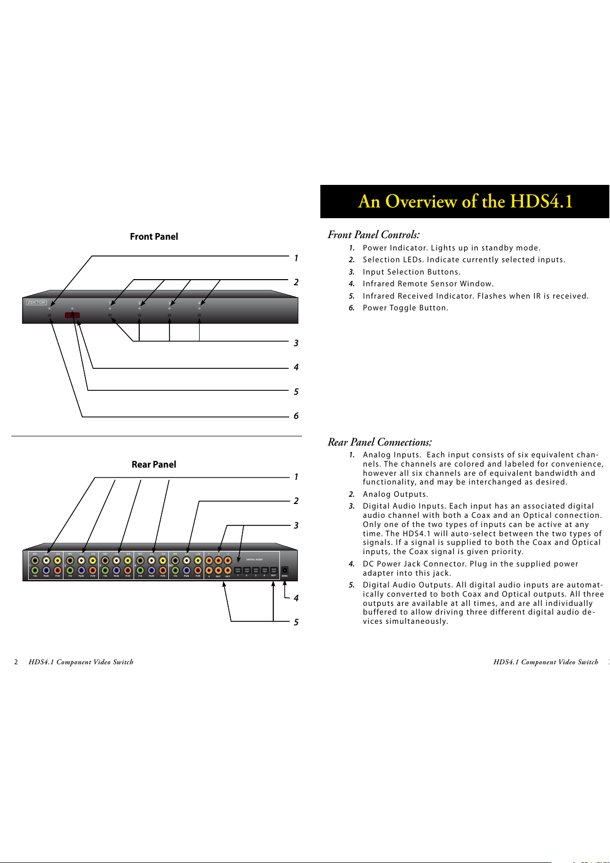
1.
2.
3.
•
•
•
•
Step 2: Enable or Disable Front Panel and / or IR Control Functions
1 2 3 4
ZEKTOR
Enable / Disable
IR Control Functions
Enable / Disable
Front Panel Buttons
Exit Setup Mode
All manuals and user guides at all-guides.com

16 HDS4.1 Component Video Switch
17HDS4.1 Component Video Switch
Step 1: Reset All Parameters to Factory Defaults
1 2 3 4
ZEKTOR
Start by pressing and
holding the Power
button...
12...while continuing to hold the Power
button, press and hold both the‘2’
and the ‘3’ buttons.
After about 4 seconds, the display will flash
indicating all parameters have been restored
to their factory programmed values.
3
Resetting to Factory Defaults
If, for what e ver reason, yo u’d l i k e t o reset your HDS4.1 back to i t s
factory condition, this is easily done...
Step 1: Reset All Parameters to Factory Defaults
First press and hold the Powe r b u t t o n
Wh i l e c o n t i n u i n g to hold the Power Button, pre s s a n d h o l d
both the ‘2’ and ‘3’ buttons.
After holding all buttons for about ‘4’ seconds, the display
will flash indicating all parameters have been restored to
their factory programmed values.
1.
2.
3.
All manuals and user guides at all-guides.com

18 HDS4.1 Component Video Switch
19HDS4.1 Component Video Switch
Specifications
Specifications:
Analog Channels
Bandwidth @ -0.1db:
Bandwidth @ -3db:
Resolution:
Input Coupling:
Output Coupling:
Digital Audio Channels
Inputs:
Outputs:
Maximum Transfer Rate:
Digital Audio Modes:
Coax Input Level Range:
Coax Output Level:
Power Requirements:
Optional International:
Power Supply:
Dimensions:
Warranty:
0Hz - 70MHz, All channels
Greater than 200MHz, All channels
480i - 1080p, All HDTV modes
D.C.
D.C.
4 Coax, 4 Optical, (Auto conversion between formats)
2 Coax, 1 Optical, (Simultaneous)
13.2Mb/S
PCM, DD5.1, DTS, All modes
200mV - 7.0V (PC Soundcard Compatible)
500mV Nominal
90-120VAC, 60Hz, 15W
90-264VAC, 47-63Hz, 15W
Wall Mount, 9V @ 500ma, U.L. Listed
Rack Mountable, 17”W x 6.5”D x 1.75”H
Two Year Parts and Labor
All manuals and user guides at all-guides.com
all-guides.com

20 HDS4.1 Component Video Switch
21HDS4.1 Component Video Switch
Contact Information
Instructions for Returning Items
Pl e a s e r e t a i n t h e d ated sales rece i p t a s e v i d e n c e o f t h e d ate of
purc h a s e. Yo u w i l l n e e d i t for any wa r ra n t y ser v i c e. I f you bought
the product through a dealer, installer, or reseller, you will need to
re t u r n t h e p r o d u c t to t h e p o i n t o f s a l e.
E-mail us, or call us, using the information listed under “Customer
Ser vice Contac t I nfo r m a t i o n”, for a Return to Manufac t u rer Au t h o r i-
zation (RMA) number. Describe briefly the reasons for your request-
ed re t u r n .
Yo u m u s t receive an RMA # b e fore yo u return any goods to us. The
RMA # must appear on your return packing label or on the outside
of the box . M e rchandise without a RMA # will be re f u s e d . R MA’s a re
va l i d for t went y ( 2 0 ) d ays from dat e o f i s s u a n ce.
All returned merchandise must be shipped in the original packaging.
If it is not in the original pack a g i n g, ZEK TOR will not be held liable
for damage during shipment. Shipments of returns must be prepaid,
and we w i l l n o t a c cept CO D retur n s.
Customer Service Contact Information:
Zektor
12675 Danielson Ct.
Suite 401
Poway, CA 92064
Phone: 858-748-8250
Fax: 858-748-8224
E-mail: customerservice@zektor.com
Website: www.zektor.com
Warranty Policy
Warranty Policy
ZEK TO R w a r r a n t s t h i s p roduc t a g a i n s t d e fec t s i n m a terial and work-
manship under normal use and ser v i c e for t wo years fro m t h e o r i g i -
nal date of purchase. ZEKTOR, at its option, shall repair or replace
the defe c tive u n i t c overe d b y t h i s war rant y.
In order to k e e p t h i s w a r r a n t y i n e f fec t , t h e p r o d u c t must have been
handled and used as prescribed in the instructions accompanying
this wa r ra n t y. This warranty does not cove r a ny damage due to acci-
dent , m i s u s e , a b u s e, or negligence. This warranty is valid only if the
product is used as specified in the product documentation.
Repair or re p l a c e m e n t , a s p rovided under this warra n t y, i s y o u r
exclusive remedy. ZEKTOR shall not be liable for any incidental or
consequential damages. Implied warranties of merchantability and
fitness for a particular purpose on this product are limited in dura-
tion to t h e d u r a t i o n o f t h i s war rant y.
Some states/countries do not allow the exclusion or limitation of
incidental or consequential damages, so the above limitation or
exc l u s i o n m ay not apply to yo u . S o m e s t a tes/countries do not al-
low l i m i t a t i o n s o n h ow long an implied warranty lasts, so the above
limitat i o n m a y n o t a p p l y to you. Th i s war rant y gives yo u s p e c i f i c
legal rights, a n d you may also have o t h e r r i g h t s t h at var y fro m s t a t e
to s t a t e a n d countr y to c o u n t r y.
Return & Exchange
Shipment of product is as advertised by product. Upon receipt of
merchandise inspect product carefully, should you find that the
product does not meet your expectations, or satisfaction, contact
us at o n c e a n d t e l l u s your conce r ns, s o we may make eve r y e f for t to
satisfy your purchase.
All manuals and user guides at all-guides.com

ZEKTOR
ZEKTOR
12675 Danielson Ct
Suite 401
Poway, CA 92064
858•748•8250
www.zektor.com
All manuals and user guides at all-guides.com
Other manuals for HDS4.1
1
Table of contents
Other Zektor Switch manuals

Zektor
Zektor HDVI5 User manual

Zektor
Zektor HDVI5 User manual

Zektor
Zektor CVS4 Owner's manual

Zektor
Zektor HDA604 User manual

Zektor
Zektor MAS7.1 User manual

Zektor
Zektor HDMI5 User manual

Zektor
Zektor HDMI5 User manual

Zektor
Zektor ZEKTOR MAS3 User manual

Zektor
Zektor CVS4 User manual

Zektor
Zektor DVS5.1 User manual