manuals.online logo
Brands
  1. Home
  2. •
  3. Brands
  4. •
  5. Zephyr
  6. •
  7. Ventilation Hood
  8. •
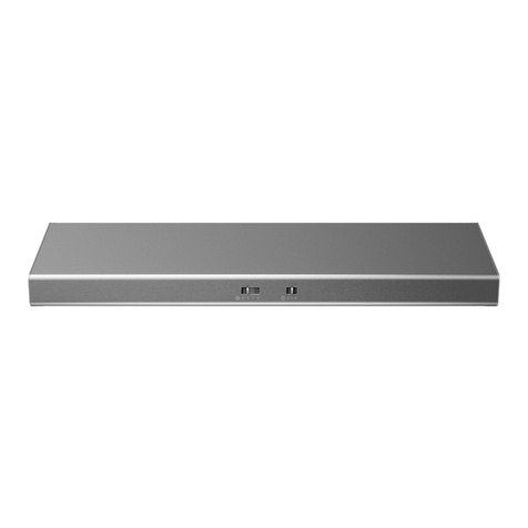
  9. Zephyr Typhoon AK2100BS Installation guide

Zephyr Typhoon AK2100BS Installation guide

Other manuals for Typhoon AK2100BS

1

This manual suits for next models

20

Other Zephyr Ventilation Hood manuals

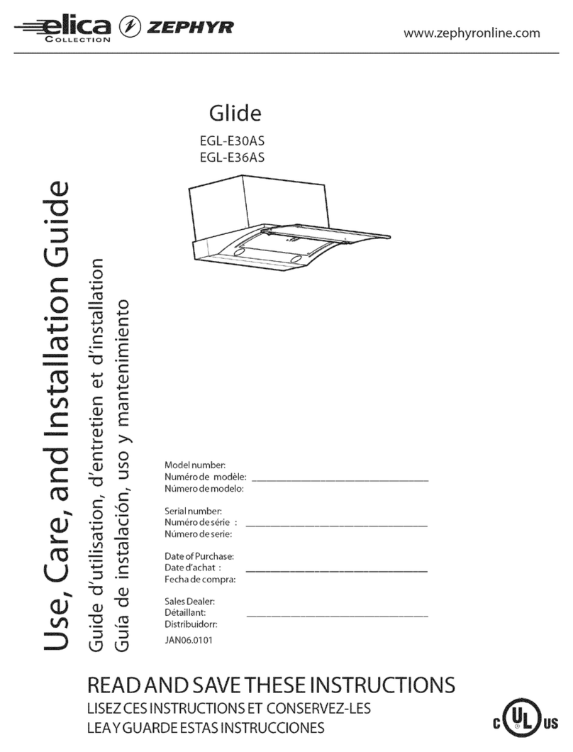
Zephyr Tempest II AK7500ASX Installation guide

Zephyr

Zephyr Tempest II AK7500ASX Installation guide

Zephyr AK9134B Installation guide

Zephyr

Zephyr AK9134B Installation guide

Zephyr AKI 124S Use Installation guide

Zephyr

Zephyr AKI 124S Use Installation guide

Zephyr Roma Island ZRM-E36CS Installation guide

Zephyr

Zephyr Roma Island ZRM-E36CS Installation guide

Zephyr ZAN-E24CS Installation guide

Zephyr

Zephyr ZAN-E24CS Installation guide

Zephyr Siena Installation guide

Zephyr

Zephyr Siena Installation guide

Zephyr Monsoon DCBL AK9428AS Installation guide

Zephyr

Zephyr Monsoon DCBL AK9428AS Installation guide

Zephyr Venezia ZVE-E30AS User manual

Zephyr

Zephyr Venezia ZVE-E30AS User manual

Zephyr Z1C01ML Installation guide

Zephyr

Zephyr Z1C01ML Installation guide

Zephyr Siena ZSI-E30CS User manual

Zephyr

Zephyr Siena ZSI-E30CS User manual

Zephyr Siena ZSI-E36AS Installation guide

Zephyr

Zephyr Siena ZSI-E36AS Installation guide

Zephyr Monsoon II Installation guide

Zephyr

Zephyr Monsoon II Installation guide

Zephyr CACHE CCA-E30ASX Use Installation guide

Zephyr

Zephyr CACHE CCA-E30ASX Use Installation guide

Zephyr Roma Island ZRM-E36BS Installation guide

Zephyr

Zephyr Roma Island ZRM-E36BS Installation guide

Zephyr SAVONA ZSA-M90AS Installation guide

Zephyr

Zephyr SAVONA ZSA-M90AS Installation guide

Zephyr Gust AK7100BS-BF Installation guide

Zephyr

Zephyr Gust AK7100BS-BF Installation guide

Zephyr AK08 S Series User manual

Zephyr

Zephyr AK08 S Series User manual

Zephyr ZRC-7000 Installation guide

Zephyr

Zephyr ZRC-7000 Installation guide

Zephyr Siena ZSI-E30AS-ES Installation guide

Zephyr

Zephyr Siena ZSI-E30AS-ES Installation guide

Zephyr ZMI-M90G Installation guide

Zephyr

Zephyr ZMI-M90G Installation guide

Zephyr Monsoon DCBL AK9428AS Installation guide

Zephyr

Zephyr Monsoon DCBL AK9428AS Installation guide

Zephyr Savona Wall ZSA-E30BS Installation guide

Zephyr

Zephyr Savona Wall ZSA-E30BS Installation guide

Zephyr Duo Is. ADL-E42ASX User manual

Zephyr

Zephyr Duo Is. ADL-E42ASX User manual

Zephyr Slope ESL-M90AS Installation guide

Zephyr

Zephyr Slope ESL-M90AS Installation guide

Popular Ventilation Hood manuals by other brands

Gorenje S3 IHGC963S4X manual

Gorenje

Gorenje S3 IHGC963S4X manual

KOBE ISX2136SQB-1 Installation instructions and operation manual

KOBE

KOBE ISX2136SQB-1 Installation instructions and operation manual

U.S. Products ADVANTAGE-100H Information & operating instructions

U.S. Products

U.S. Products ADVANTAGE-100H Information & operating instructions

Kuppersberg DUDL 4 LX Technical Passport

Kuppersberg

Kuppersberg DUDL 4 LX Technical Passport

Framtid HW280 manual

Framtid

Framtid HW280 manual

Thermador HGEW 36 FS installation manual

Thermador

Thermador HGEW 36 FS installation manual

Electrolux LFT769X user manual

Electrolux

Electrolux LFT769X user manual

AEG X69453MVO UK user manual

AEG

AEG X69453MVO UK user manual

Broan B5836SS manual

Broan

Broan B5836SS manual

Heinner HDCH-6060RGBK quick start guide

Heinner

Heinner HDCH-6060RGBK quick start guide

Baumatic AS35SS instruction manual

Baumatic

Baumatic AS35SS instruction manual

Franke FTF 604 XS V2 Instructions for use and installation

Franke

Franke FTF 604 XS V2 Instructions for use and installation

Best UCB3I30SBW installation instructions

Best

Best UCB3I30SBW installation instructions

Gram EFU 503-90 X instruction manual

Gram

Gram EFU 503-90 X instruction manual

CIARRA CBCS6803 Installation and user manual

CIARRA

CIARRA CBCS6803 Installation and user manual

sauter SHG501 Instructions for installation and use

sauter

sauter SHG501 Instructions for installation and use

Franke 392-17 User instructions

Franke

Franke 392-17 User instructions

FALMEC Polar Black 35 Instruction booklet

FALMEC

FALMEC Polar Black 35 Instruction booklet

manuals.online logo
manuals.online logoBrands
  • About & Mission
  • Contact us
  • Privacy Policy
  • Terms and Conditions

Copyright 2025 Manuals.Online. All Rights Reserved.

Use, Care, and Installation Guide
www.zephyronline.com
Model number:
Serial Number:
Date of Purchase:
Sales Dealer:
MAY15.0101 © Zephyr Ventilation LLC.
Airflow Control Technology
TM
C
Airflow Control Technology
TM
C
Typhoon
AK2100BS, B,W
AK2136BS, B,W
AK2142BS
AK2148BS
Hurricane
AK2500BS, B, W
AK2536BS, B,W
Cyclone
AK6500BS, B,W
AK6536BS, B,W
AK6542BS
9
Installation – Ducting Options
WARNING FIRE HAZARD
NEVER exhaust air or terminate duct work into spaces between walls, crawl spaces, ceiling, attics or garages.
All exhaust must be ducted to the outside.
Use metal ductwork only.
)DVWHQDOOFRQQHFWLRQVZLWKVKHHWPHWDOVFUHZVDQGWDSHDOOMRLQWVZLWKFHUWL¿HG6LOYHU7DSHRU'XFW7DSH
Some Ducting Options
side wall cap
w/gravity damper
cabinet
cabinet
soffit or crawl space
side wall cap
w/gravity damper
3-1/4”x10” rear
ducting w/side
wall gravity damper
roof pitch w/
flashing & cap
10
www.zephyronline.com
Installation – $.6SHFL¿FDWLRQV
3
1/16
”1
7/16
”
9
15/16
”
(30”) 28
1/16
”, (36”) 34”
(42”) 39
3/4
”, (48“) 45
3/4
”
5
1/16
”
2
3/4
”
8
5/8
”
(30”) 11
5/16
”, (36”) 12
1/2
”
(42”) 12
1/2
”, (48“) 12
1/2
”
1
15/16
”
elec
k/o
(30”) 29
3/4
”, (36”) 35
3/4
”
(42”) 41
3/4
”, (48“) 47
11/16
”
(30”) 14”, (36”) 17”
(42”) 19
7/8
”, (48“) 22
7/8
”
C/L
13
9/16
”
20
3/4
”
7
7/8
”
1
3/8
”
9
15/16
”
1
1/16
”
(30”) 11
5/16
”
(36”) 12
1/2
”
(42”) 12
1/2
”
(48“) 12
1/2
”
C/L
3
1/16
”
6
7/8
”
6
7/8
”
elec
k/o
TOP
SIDE
FRONT BACK
11
Installation – $.6SHFL¿FDWLRQV
(30”) 29 3/4”, (36”) 35 7/8”
14 3/4”
7”
1 7/8”
9 15/16”
11/16”
(30”) 11 3/8”
(36”) 14 3/8”
C/L
3 1/16”
6 7/8”
elec
k/o
TOP
SIDE
FRONT BACK
10 1/4”1 5/8”
Ø 6 7/8”
(30”) 27 7/8” (36”) 34”
C/L
(30”) 11 3/8” (36”) 14
3/8
”
2 1/4”
4 3/4”
22 1/8”
2 1/8”
12
www.zephyronline.com
Installation – $.6SHFL¿FDWLRQV
3
1/16
”1
7/16
”
9
15/16
”
(30”) 27
7/8
”, (36”) 33 7/8”, (42”) 39
7/8
”
4
1/2
”
1
7/8
”
8
5/8
”
12”
2”
elec
k/o
(30”) 29
3/4
”, (36”) 35
3/4
”, (42”) 41
3/4
”
(30”) 14”, (36”) 17”, (42”) 20”
C/L
15
3/8
”
22
1/4
”
6
3/8
”
1
3/8
”
9
15/16
”
1
1/16
”
C/L
3
1/16
”
5
7/8
”
5 7/8”
elec
k/o
TOP
SIDE
FRONT BACK
12”
5
1/2
”
13
Installation – 3-1/4”x10” rectangular ducting preparation
%\GHIDXOWWKH7\SKRRQDQG+XUULFDQHDUHSUHFRQ¿JXUHGIRUURXQGYHUWLFDOGXFWLQJ  
%\GHIDXOWWKH&\FORQHLVSUHFRQ¿JXUHGIRUURXQGYHUWLFDOGXFWLQJ
1. Using a Philips-head screwdriver remove the screws and
round vertical transition adapter from top of hood body. 2. Replace round vertical transition adapter with
rectangular transition adapter. Do not secure to hood body
yet.
3ODFH[UHFWDQJXODUFROODURQWRSRIUHFWDQJXODU
transition adapter. Secure rectangular adapter and
rectangular collar to hood body using the previously
removed screws from step 1.
3-1/4"x10" Rectangular Vertical Ducting
14
www.zephyronline.com
Installation – 3-1/4”x10” rectangular ducting preparation
%\GHIDXOWWKH7\SKRRQDQG+XUULFDQHDUHSUHFRQ¿JXUHGIRUURXQGYHUWLFDOGXFWLQJ  
%\GHIDXOWWKH&\FORQHLVSUHFRQ¿JXUHGIRUURXQGYHUWLFDOGXFWLQJ
1. Using a Philips-head screwdriver remove the screws and
round vertical transition adapter from the top of the hood.
4. Replace round vertical transition adapter with
rectangular transition adapter. Do not secure to hood body
yet.
3ODFH[UHFWDQJXODUFROODURQEDFNRIKRRG
and secure using the screws that previously secured the
rectangular cover plate.
3-1/4"x10" Rectangular Horizontal Ducting
3ODFH[UHFWDQJXODUFRYHUSODWHRYHUWKH
rectangular opening on top of hood from step 4. Secure
rectangular transition adapter and cover plate to hood body
using the previously removed screws from step 1.
3. Typhoon ONLY. Remove the two plastic air diverter
blocks. The blocks are located in the hood and can be
accessed from the top when the round transition adapter is
removed.
2. Using a Philips-head screwdriver, remove the screws
DQG[UHFWDQJXODUFRYHUSODWHIURPEDFNRIKRRG
15
Installation – Preparing Electrical
ELECTRICAL
WARNING
$OO(OHFWULFDOZRUNPXVWE\SHUIRUPHGE\TXDOL¿HGHOHFWULFLDQRUSHUVRQZLWKVLPLODUWHFKQLFDO
knowledge and background.
For personal safety, remove house fuse or open circuit breaker before beginning installation. Do not use
extension cord or adapter plug with this appliance.
Follow national electrical codes or prevailing local codes and ordinances.
Electrical Supply:
This appliance requires a 120V 60Hz electrical supply, and connected to an individual, properly
grounded branch circuit, protected by a 15 or 20 ampere circuit breaker or time delay fuse. Wiring must
be 2 wire w/ ground. Please refer to Electrical Diagram labeled on product.
Cable Lock:
$FDEOHORFNLQJFRQQHFWRUQRWVXSSOLHGPLJKWDOVREHUHTXLUHGE\ORFDOFRGHV&KHFNZLWKORFDO
requirements and codes, purchase and install appropriate connector if necessary.
Cable Lock
16
www.zephyronline.com
Installation – Mounting the Range Hood
 3UHSDUHGXFWORFDWLRQRQKRRGYHUWLFDORU
KRUL]RQWDO5HIHUWR3DJHVIRUGXFWLQJ
options.
2. Measure and cut out duct and electrical
openings in cabinet or wall to match up with
the hood. Ducting and electrical dimensions
can be found on Pages 10-12. Note: Make
sure duct opening is large enough to apply
aluminum duct tape.
3. Reinforce cabinet bottom with wood strips
if additional strengthening is required or if
cabinets are framed.
4. Remove bottom panel from hood using a
Philips head screwdriver to remove each of
the screws. Also disconnect lighting harness
by pressing in on the clip to release the lights
from the internal wiring.
 ,QVWDOOZRRGVFUHZVWRFDELQHWERWWRP
by following the installation screw hole
dimensions on Page 10. These screws will be
used to secure the hood to the cabinet.
6. Lift hood onto screws located on cabinet
bottom and lock into place. Make sure all
NH\KROHVFRYHUWKHVFUHZV7LJKWHQHDFK
screw to secure hood to cabinet. Note: For
30” Typhoon models you will need an 8” - 10”
long shaft for your screwdriver/drill to reach the
front screws.
7. Install electrical.
8. Install duct work and seal with aluminum duct
tape.
9. Power up hood and check for leaks around
duct tape and test all functions.
10. Reinstall bottom panel and re-connect lighting
harness.
11. Slide residue cups into their openings on the
bottom of the hood. Install safety grilles over
each blower opening and secure with the two
safety grille screws.
Hood is designed for installation under a
kitchen cabinet. See Fig. 1 for details.
bottom panel &
lighting harness
wood blocking
installation screws
and key-holes
duct work
residue cups &
safety grilles
electrical
duct tape
Fig 1
17
&RQWUROV$&79HUL¿FDWLRQ±AK21 Capacitive Touch
Q 2 3
1Power / Delay Off 4Lights On/Off
5Speed Indicators
Fan Speed Decrease Fan Speed Increase3
1Power / Delay Off Button
- Button will turn power on and off for entire hood (fan and lights).
- Hood will remember the last speed and light level it was last turned off at.
(Example: Press button to turn off hood when on fan speed 3 and high lights.
Press button again and the hood will turn back on at speed 3 and high lights.)
Delay Off
- With the fan on, press and hold the button for two seconds. The fan will change to
speed Q and the 5 minute delay off timer will start.
- Speed indicators starting with level 5 will illuminate and blink in accordance with the time
remaining until the fan an lights automatically turn off.
- Pressing button while delay off function is enabled will turn the hood off and cancel
the delay off function.
ACT Verification
- Airflow Control Technology (ACT) allows the installer to set the maximum fan CFM to
align with local codes and regulations.
- To verify the maximum fan CFM:
- With hood off, hold the button for five seconds. If all speed level indicators
illuminate = default maximum CFM. If speed Q, 2 & 3 level indicators illuminate =
390 maximum CFM. If speed Q & 2 level indicators illuminate = 290 maximum CFM
2Fan Speed Decrease Button
- Press this button to decrease fan speed. 6, 5, 4, 3, 2, Q (Quiet).
- If fan is off, press this button to turn on fan at last speed it was turned off at.
3Fan Speed Increase Button
- Press this button to increase fan speed. Fan on, Q (Quiet), 2, 3, 4, 5, 6
- If fan is off, press this button to turn on fan at last speed it was turned off at.
4Lights Button
- Lights are two levels, high and low.
- From off, press one time for high. Press again for low. Press again to power lights off.
5Speed Level Indicators
- Fan is six speed levels. Q (Quiet), 2, 3, 4, 5 and 6.
4 5 6