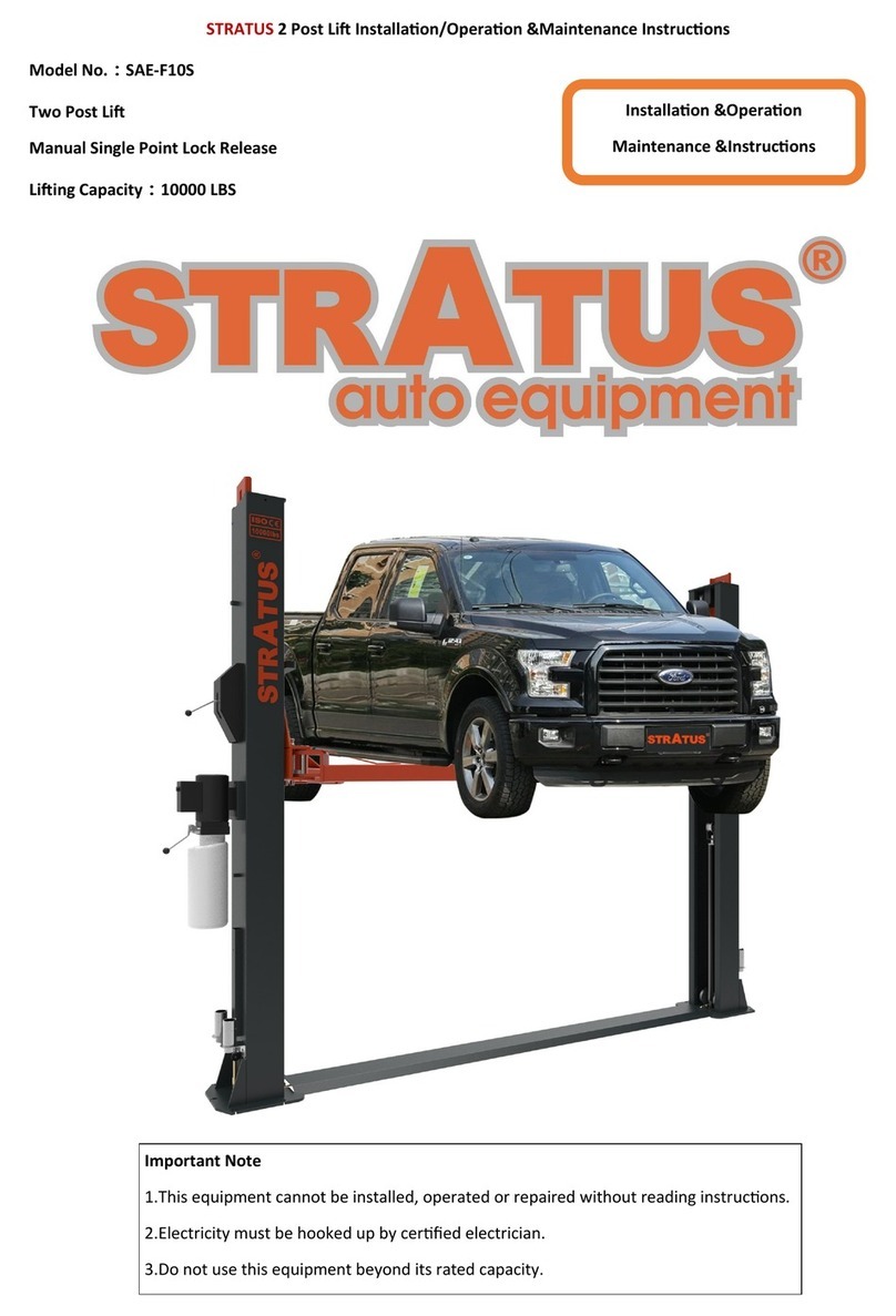
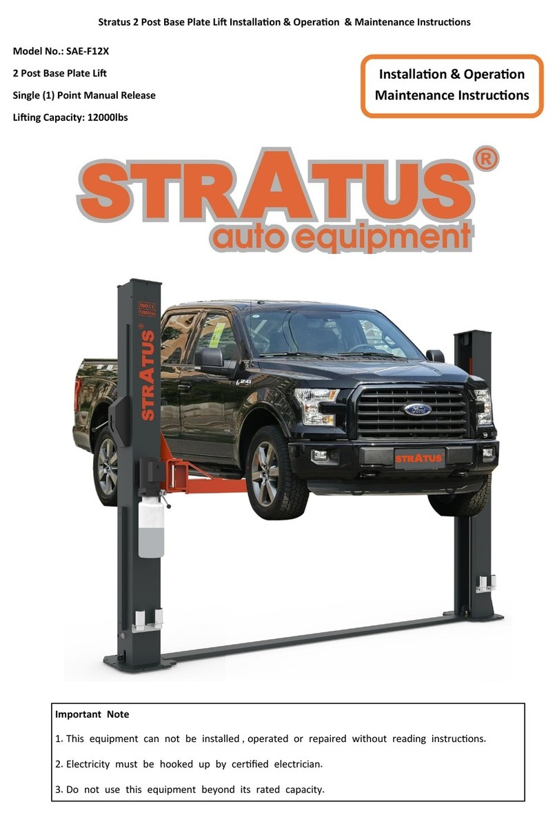
Stratus SAE-F10P Guide

Model No. SAE-F10P
Chain drive 2 post Lift
Single Point Manual Release
Lifting Capacity 10,000 lbs
Installation & Operation &
Maintenance Instructions
Important Note
1. This equipment can not be installed, operated or repaired without reading instructions.
2. Electricity must be hooked up by certified electrician.
3. Do not use this equipment beyond its rated capacity.

STRATUS Floor Plate 2 post Lift Installation & Operation & Maintenance Instructions
2
TABLE OF CONTENTS
1. Packing, transport and storage .......................................................................................................................................5
1.1 Packing..............................................................................................................................................................................5
1.2 Transport...........................................................................................................................................................................5
1.3 Storage..............................................................................................................................................................................5
2. Description of the machine...............................................................................................................................................6
2.1 Fixed structure.................................................................................................................................................................6
2.2 Moving units.....................................................................................................................................................................6
2.3 Lift unit...............................................................................................................................................................................6
2.5 Safety device....................................................................................................................................................................7
3. Technical specifications....................................................................................................................................................8
4. Safety....................................................................................................................................................................................10
4.1 Important notices...........................................................................................................................................................10
4.2 Qualified personnel .......................................................................................................................................................10
4.3 Danger notices...............................................................................................................................................................10
4.4 Training............................................................................................................................................................................10
4.5 Warning signs.................................................................................................................................................................11
5. Installation...........................................................................................................................................................................12
5.1 Tool required...................................................................................................................................................................12
5.2 Checking for room suitability........................................................................................................................................13
5.3 Lighting.......................................................................................................................................................................13
5.4 Floor requirement.....................................................................................................................................................13
5.5 Site layout..................................................................................................................................................................13
5.6 Anchoring columns...................................................................................................................................................14
5.7 Routing the equalizer cables..................................................................................................................................15
5.8 Install limit switch...........................................................................................................................................................16
5.9 Routing the safety release cable............................................................................................................................22
5.10 Installation of power unit.............................................................................................................................................23
5.11 Connection of hydraulic hoses...................................................................................................................................23
5.12 Make the electrical connection..................................................................................................................................23
5.13 Oil filling and bleeding.................................................................................................................................................24
5.14 Installation of lifting arms and adjustment of arm locks.........................................................................................25
5.15 Check before start-up.................................................................................................................................................27
5.15.1 General checks...................................................................................................................................................27
5.15.2 Mechanical safeties for proper installation.................................................................................................27
5.15.3 Equalizer cable for proper installation.........................................................................................................27
5.15.4 Hydraulic system for proper operation........................................................................................................27
5.16 Check with load ...........................................................................................................................................................27
6. Operation and use.............................................................................................................................................................28
6.1 Controls...........................................................................................................................................................................28
6.2 Vehicle positioning....................................................................................................................................................28
6.3 Lifting..........................................................................................................................................................................28
6.4 Standing.....................................................................................................................................................................29
6.5 Lowering....................................................................................................................................................................29
7. Maintenance........................................................................................................................................................................30
7.1 Ordinary maintenance...................................................................................................................................................30
7.2 Periodic maintenance....................................................................................................................................................30
8. Troubleshooting.................................................................................................................................................................31
9. Parts list...............................................................................................................................................................................32
9.1 Explode drawing and parts list.....................................................................................................................................32
9.2 Power side column and parts list ................................................................................................................................34
9.3 Off side column and parts list.......................................................................................................................................37
9.4 Carriage and parts list...................................................................................................................................................40
9.5 Arm assembly and parts list.........................................................................................................................................41
10. Special notes....................................................................................................................................................................42

STRATUS Floor Plate 2 post Lift Installation & Operation & Maintenance Instructions
3
10.1 Environmental damage...............................................................................................................................................42
10.2 Dismantling...................................................................................................................................................................42
10.3 Disposal........................................................................................................................................................................42
10.4 Noise declaration.........................................................................................................................................................43

STRATUS Floor Plate 2 post Lift Installation & Operation & Maintenance Instructions
4
Foreword
Notes on the operating instructions
The present ORIGINAL OPERATING INSTRUCTIONS are designed to provide sufficient instruction for the
safe operation of the product. The information is provided clearly and concisely. The chapters are arranged by
letter and the pages are numbered continuously.
Our products are subject to ongoing development. Our company reserves the right to alter the design,
equipment and technical features of the system. No guarantee of particular features of the product should
therefore be assumed from the present operating instructions.
Safety notices and text mark-ups
Safety instructions and important explanations are indicated by the following graphics:
Indicates an extremely hazardous situation. Failure to comply with this instruction will result in
severe irreparable injury and even death.
Indicates an extremely hazardous situation. Failure to comply with this instruction may result in
severe irreparable injury and even death.
Indicates a hazardous situation. Failure to comply with this instruction may result in
slight to medium injury.
Indicates a material hazard. Failure to comply with this instruction may result in material damage.

STRATUS Floor Plate 2 post Lift Installation & Operation & Maintenance Instructions
5
1. Packing, transport and storage
All packing, lifting, handling, transport and unpacking operations are to be performed exclusively by expert
personnel with knowledge of the lift and the contents of this manual.
1.1 Packing
The packing of the lift is delivered in following components:
•1 base unit packed in a steel frame, wrapped up in non-scratch material, including all the accessories.
•1 power unit packed in a carton box.
1.2 Transport
See Fig 1, packing can be lifted or moved by lift trucks, cranes or bridge cranes. In case of slinging, a second
person must always take care of the load, in order to avoid dangerous oscillations.
During loading and unloading operation, goods must be handled by vehicles or ships.
At the arrival of the goods, verify that all items specified in the delivery notes are included. In case of missing parts,
possible defects or damage due to transport operations.
If finding missing parts, possible defects or damage due to transport, one should examine damaged cartons
according to <<Packing List.>> to verify the condition of damaged goods and missing parts, also the person in
charge or the carrier must be immediately informed.
The machine is heavy goods! Don’t take manpower load and unload and transporting way into consideration, the
safety of working is important.
Furthermore, during loading and unloading operation goods must be handled as shown in the picture. (Fig 1)
Fig 1
1.3 Storage
The machine equipment should be stocked in the warehouse, if stocked outside should do the disposal well of
waterproof.
Use box truck in the process of transport, use container storage when shipping.
The control box should be placed perpendicularly during the transport; and prevent other goods from extrusion.
The temperature for machine storage: -10ºC -- 40ºC

STRATUS Floor Plate 2 post Lift Installation & Operation & Maintenance Instructions
6
2. Description of the machine
The electro-hydraulic 2-post lift is a fixed installation. This means that it is anchored to the ground and built for lifting
and positioning automobiles and vans at a certain height off the ground.
The lift consists of the following main parts(see Fig.2):
Fig.2
2.1 Fixed structure
Posts and steel plate:
2 posts and command built with bent steel plate. The base is welded to a drilled plate to be anchored to the floor.
The hydraulic power unit are attached to the command post. Inside each post are the moving parts to lift the
vehicles.
The column set on the base.
2.2 Moving units
Carriages + arms:
1. Both carriages built with welded steel plate. It joints by chain and the cable, and at the bottom to the lift arms by
means of pins.
2. The carriage moves along the post, guided by plastic sliding pads. Located inside the post itself.
3. Two telescopic arms, one long and one short, built wit tubular steel with a pad at each end that can be height
adjusted to hold the car and on the opposite side the carriage connection hole.
2.3 Lift unit
Hydraulic cylinders + power unit:
2 hydraulic cylinders, the carriages run by chains and synchronized by steel cables.
1 hydraulic unit, on the command side, to set the cylinders run
The hydraulic power unit consists of:
1. An electric motor
2. A geared hydraulic pump
3. Descent hand-valve equipped with a manual oil drain valve (see the use and maintenance chapter)

STRATUS Floor Plate 2 post Lift Installation & Operation & Maintenance Instructions
7
4. A maximum pressure valve.
5. Oil tank
6. An oil delivery and return flexible pipe to the cylinders feeding circuit
Note: The oil delivery pipe may be under pressure.
Fig.3
2.5 Safety device
The safety devices include:
1 Mechanical safety device for carriage
2 Arms locking system
3 A synchronous device to control the carriages movement.
4 End limit switches
5 General hydraulic safety devices
These safety devices will be described in further detail in the following chapters.

STRATUS Floor Plate 2 post Lift Installation & Operation & Maintenance Instructions
8
3. Technical specifications
CAPACITY
10,000 lbs (4,500kg)
Max. lifting height with no pad extension
74 7/8”(1900mm)
Min. adaptor height
3 15/16” (100mm)
Overall height
111 1/4”(2824mm)
Overall width
134 1/4”(3410mm)
Drive through width
103 1/4” (2622mm)
Lifting time
≤50
S
Lowering time
≤40
S
Noise level
<85 dB(A)/1m
Working temperature
41°F - 104°F
Voltage
220V/60Hz/1PH
Power
2.2KW /3HP
Breaker
30A
Hydraulic Fluid Requirement
3-5 Gallons AW32/AW46
Average weight of package
1411 lbs (640kg)

STRATUS Floor Plate 2 post Lift Installation & Operation & Maintenance Instructions
9
Fig.5 Layout
Fig. 4

STRATUS Floor Plate 2 post Lift Installation & Operation & Maintenance Instructions
10
4. Safety
4.1 Important notices
This 2-posts lift is specially designed for lifting motor vehicles that weighs within its outmost lifting capacity. Users
are not allowed to use it for any other purposes. Otherwise, we, as well as our sales agency, will not bear any
responsibility for accidents or damages of the lift. Make sure to pay careful attention to the label of the lifting
capacity attached on the lift and never try to lift cars with its weight beyond.
Read this manual carefully before operating the machine so as to avoid economic loss or personnel casualty
incurred by wrong operation. Without professional advice, users are not permitted to make any modification to the
control unit or whatever mechanical unit.
4.2 Qualified personnel
➢Only these qualified staff, who have been properly trained, can operate the lift.
➢Electrical connection must be done by a competent electrician.
➢People who are not concerned are not allowed in the lifting area.
4.3 Danger notices
➢Do not install the lift on any asphalt surface.
➢Read and understand all safety warnings before operating the lift.
➢The lift, if is not specially designed upon customer’s request, is not fit for outdoor use.
➢Keep hands and feet away from any moving parts. Keep feet clear of the lift when lowering.
➢Only these qualified people, who have been properly trained, can operate the lift.
➢Do not wear unfit clothes such as large clothes with flounces, tires, etc, which could be caught by moving parts
of the lift.
➢To prevent evitable incidents, surrounding areas of the lift must be tidy and with nothing unconcerned.
➢The lift is simply designed to lift the entire body of vehicles, with its maximum weight within the lifting capacity.
➢Always ensure the safety latches are engaged before any attempt to work near or under the vehicle.
➢Make sure to place the lifting pads to the positions as suggested by vehicle makers and when gradually lift the
vehicle to the desired height, operators should be certain that the vehicle will not slant, roll-over or slide in lifting
process.
➢Check at any time the parts the lift to ensure the agility of moving parts and the performance of synchronization.
Ensure regular maintenance and if anything abnormal occurs, stop using the lift immediately and contact our
dealers for help.
➢Lower the lift to its lowest position and do remember to cut off the power source when service finishes.
➢Do not modify any parts of the lift without manufacturer’s advice.
➢If the lift is going to left used for a long time, users are required to:
a. Disconnect the power source;
b. Empty the oil tank;
c. Lubricate the moving parts with hydraulic oil.
4.4 Training
Only these qualified people, who have been properly trained, can operate the lift. We are quite willing to provide
professional training for the users when necessary.
Attention: For environment protection, please dispose the disused oil in a proper way.

STRATUS Floor Plate 2 post Lift Installation & Operation & Maintenance Instructions
11
4.5 Warning signs
All safety warning signs attached on the machine are for the purpose of drawing the user’s attention to safety
operation. The labels must be kept clean and need to be replaced when they are worn-out or have dropped. Read
the explanations of the labels carefully and try to memorize them.

STRATUS Floor Plate 2 post Lift Installation & Operation & Maintenance Instructions
12
5. Installation
Only skilled technicians, appointed by the manufacturer, or by authorized dealers, must be allowed to carry
out installation. Serious damage to people and to the lift can be caused if installations are made by
unskilled personnel.
Always refer to the exploded views attached during installation.
5.1 Tool required
Rotary Hammer Drill D.20
Carpenter’s Chalk
Hammer
Screw Sets
Level Bar
Tape Measure (7.5m)
English Spanner (12")
Pliers
Ratchet Spanner With Socket (28#)
Socket Head Wrench (3#, 5#, 8#)
Wrench set
(10#, 13#, 14#, 15#, 17#, 19#, 24#, 27#, 30#)
Lock Wrench

STRATUS Floor Plate 2 post Lift Installation & Operation & Maintenance Instructions
13
5.2 Checking for room suitability
The lift has been designed to be used in covered and sheltered places free of overhead obstructions.
The place of installation must not be next to washing areas, painting workbenches, solvent or varnish deposits. The
installation near to rooms, where a dangerous situation of explosion can occur, is strictly forbidden. The relevant
standards of the local Health and Safety at Work regulations, for instance, with respect to minimum distance to wall
or other equipment, escapes and the like, must be observed.
5.3Lighting
Lighting must be carried out according to the effective regulations of the place of installation. All areas next to the lift
must be well and uniformly lit.
5.4Floor requirement
The lift MUST be installed on 3000 PSI concrete with the minimum thickness 6” and an extension of at least 4’ from
anchoring points. New concrete must be adequately cured by at least 20 days minimum.
Specifications of concrete must be adhered to. Failure to do so could cause lift failure resulting in personal
injury or death.
A level floor is suggested for proper installation. Small differences in floor slope may be compensated for
by proper shimming. Any major slope change will affect the level lifting performance. If a floor is of
questionable slope considering to pour the new concrete slab.
5.5Site layout
•Now locate the lift according to the floor plan the figure 24, use a carpenters chalk line to layout a grid for the
column locations.
•After the column locations are properly marked, use a chalk or crayon to make an outline of the columns on the
floor at each location using the column base plates as a template.
•Double check all dimensions and make sure that the bases of each column are square and aligned with the
chalk line.
Fig. 5 –Floor Plan

STRATUS Floor Plate 2 post Lift Installation & Operation & Maintenance Instructions
14
5.6Anchoring columns
•Use the base plate on the column as a guide, drill each hole in the concrete approximately 6” deep with rotary
hammer drill D.20. To assure full holding power, do not ream the hole or allow drill to wobble;
•After drilling, remove dust thoroughly from each hole using compressed air and/ or wire brush. Make certain
that the column remains aligned with the chalk line during this process;
•Assemble the washers and nuts on the anchors then tap into each hole with a hammer until the washer rests
against the base plate. Be sure that if shimming is required that enough threads are left exposed;
•If shimming is required, insert the shims as necessary under the base plate so that when the anchor bolts are
tightened, the columns will be plumb;
•With the shims and anchor bolts in place, tighten by securing the nut to the base. DO NOT use an impact
wrench for this procedure;
•Anchor another column as outlined in above steps;
•Check to make sure that the columns for square-ness and plumb are as shown in the figure 28.
The requirements for column’s square-ness and plumb must be adhered to. Failure to do so could cause
lift failure resulting in personal injury or death.
Fig.6

STRATUS Floor Plate 2 post Lift Installation & Operation & Maintenance Instructions
15
Note: Anchor bolts driven into the ground at least 150mm.
Drilling Cleaning Bolting
Fig. 7
5.7Routing the equalizer cables
The equalizer cables should be checked weekly for equal tension. Failure to do this will cause uneven
lifting. The cables should always be adjusted so that they are equal tension when resting on the safety
locks.
•Use an appropriate lifting equipment to raise the carriage to the first latch position. Be sure the carriage is
engaged securely before attempting to route the equalizer cables. Carriages must be equal height from the
floor before proceeding;
•With the carriages in equal height, fit the cable end-ups through the small holes of the carriages (ref. fig. 8):
•Route the equalizer cables referring to the diagram (fig. 8). Make sure the cables in the place on the pulleys.
Make sure the cables routed properly;
•After the equalizer cables have been routed, adjust the nuts M12 to make each cable in equal tension;
The strength plate of carriage
Pass through the cable from
the bottom to the top of two
strength plate of the carriages.
Fig. 8

STRATUS Floor Plate 2 post Lift Installation & Operation & Maintenance Instructions
16
5.8 Install limit switch
1. View of the limiter switches (Fig.9):
Fig. 9
2. Install the limiter switch inside of the main column (Fig.10):
Fig. 10
Limiter switch is installed
inside of main column
Connect to motor
Wire#A1 & R

STRATUS Floor Plate 2 post Lift Installation & Operation & Maintenance Instructions
17
3. Connect the limiter switch wire to the motor:
3.1 Open the cover of the motor (Fig. 11)
Fig. 11
3.2 Disconnect the ground wire, take out theAC contactor (Fig. 12).
Note: Recommend to change the direction of the AC contactor to make limiter switch wire get out from the
left side of the motor and the power cord get out from the right side of the motor.
Fig. 12
Wire between A1 and No.3

STRATUS Floor Plate 2 post Lift Installation & Operation & Maintenance Instructions
18
3.3 Remove the wire betweenA1 and No.3 shows as above picture (Fig. 13).
Fig. 13
3.4 Replace the original short power cord with your own power cord if necessary (Fig. 14).
Fig. 14

STRATUS Floor Plate 2 post Lift Installation & Operation & Maintenance Instructions
19
3.5 Connect the ground wire on the ground stud located at lower right corner (Fig. 15).
Fig. 15
3.6 Remove the white wire sleeve on the right side of the motor (Fig. 16).
Fig. 16

STRATUS Floor Plate 2 post Lift Installation & Operation & Maintenance Instructions
20
3.7 Put the limiter switch wire sleeve on the left side of the motor (Fig.17).
Fig. 17
3.8 Connect limiter switch wire# A1 to the A1 point of theAC contactor (Fig. 18).
Fig. 18
Table of contents
Other Stratus Lifting System manuals
Stratus
Stratus SAE-UT9000 Guide
Stratus
Stratus SAE-P166M Guide

Stratus
Stratus SAE-C10P Guide

Stratus
Stratus SAE-C12XE Guide
Stratus
Stratus SAE-C12X Guide
Stratus
Stratus SAE-C10C Guide
Stratus
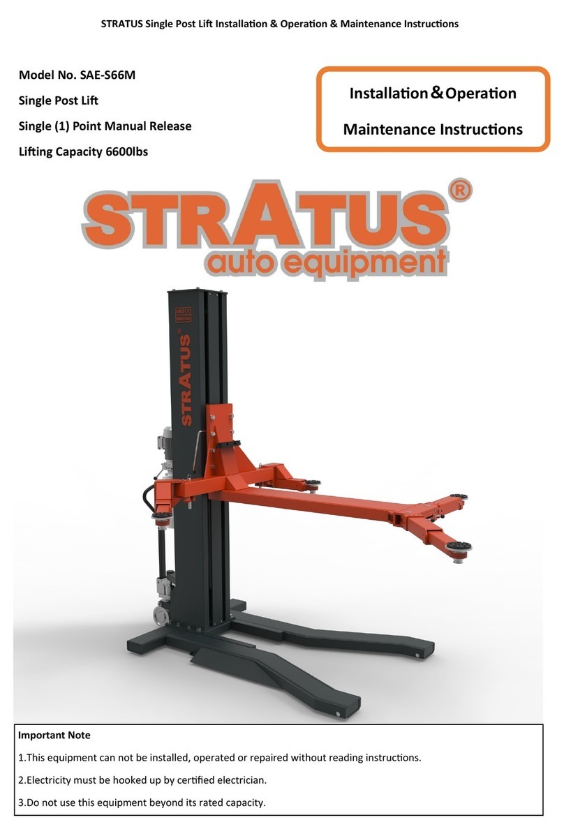
Stratus SAE-S66M User manual

Stratus
Stratus SAE-UT8000 Guide
Stratus
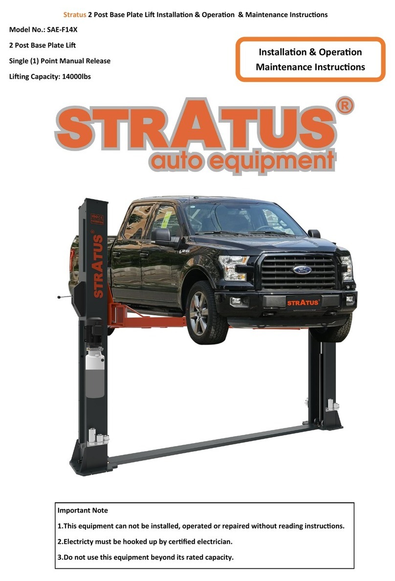
Stratus SAE-F14X Guide
Stratus
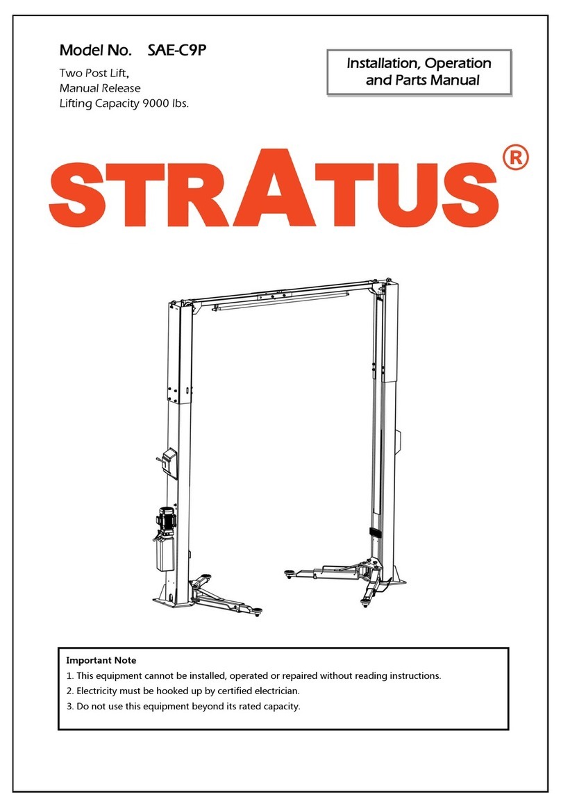
Stratus SAE-C9P Guide
