Zibro SRE 188 E User manual

SRE 188 E
2
12
22
32
42
52
62
72
MANUEL D'UTILISATION
GEBRAUCHSANWEISUNG
BRUGSANVISNING
INSTRUCCIONES DE USO
OPERATING MANUAL
ISTRUZIONI D’USO
GEBRUIKSAANWIJZING
INSTRUKCJI OBSŁUGI
3
2
6
5
4
>
1
:

E E E E E E E E E E E E E E E E E E E E E E E E E E E E E E E E E E E E E E E E E E E E E E E E E
AFAQ AFNOR CERTIFICATION 11, AVENUE FRANCIS DE PRESSENSE
93571 SAINT-DENIS LA PLAINE CEDEX
FICHE INFORMATIVE
La marque NF garantit
la qualité de cet article
suivant les normes françaises
et Règles de certification
de l’application NF 128
CONFORME A LA NORME NF D 35-300 ET AUX SPECIFICATIONS
COMPLEMENTAIRES DEFINIES PAR LES REGLES
DE CERTIFICATION DE L’APPLICATION NF 128
PRINCIPALES CARACTERISTIQUES CERTIFIEES:
• Sécurité du dispositif d’allumage
• Débit calorifique
• Efficacité des dispositifs de sécurité
• Stabilité
• Contrôle de la teneur en NOxdans les produits de combustion
• Contrôle de la qualité de la combustion (absence de CO)
• Endurance
• Intermittence
CONSEILS D’UTILISATION ET D’ENTRETIEN
Se reporter à la notice jointe à l’appareil et à la plaque de sécurité sur
l’appareil
Référence et numéro de lot ou de série de l’article : se reporter au produit
Distributed in Europe by:
PVG International B.V.
P.O.Box 96, 5340 AB OSS
Pays-Bas Tél.: +31 (0) 412 694670
En cas d’insatisfaction, consultez d’abord :
En France: PVG France SARL
4, Rue Jean Sibélius, B.P. 185
76410 SOTTEVILLE SOUS LE VAL
Tél.: 02.32.96.07.47 – Fax: 02.32.96.07.77
Si une difficulté subsistait, vous pouvez écrire au LNE
LABORATOIRE NATIONAL DE MÉTROLOGIE ET D’ESSAIS
Division Certification plurisectorielle
1, Rue Gaston Boisier - 75724 PARIS CEDEX 15
CHAUFFAGES MOBILES
A COMBUSTIBLE LIQUIDE
NF 128 02 / 02

Dear Sir, Madam,
Congratulations with your purchase of the Zibro, the number one brand among
movable heaters. You have purchased a first-class quality product, which will
serve you for many years to come. This, of course, provided you use the heater
correctly. Please read these Directions for Use first, to ensure maximum lifetime
for your Zibro.
Your heater comes with a 24-month manufacturer’s warranty on all defects in
material or workmanship.
We wish you much warmth and comfort with your Zibro.
Yours sincerely,
PVG International b.v.
Customer Service Department
1READ THE DIRECTIONS FOR USE FIRST.
2IN CASE OF ANY DOUBT,CONTACT YOUR ZIBRO DEALER.
3BEFORE YOU STARTREADING, FOLD OUT THE LAST PAGE. EEEEEEEEEE
4
42

GENERAL DIRECTIONS FOR USE
Below you will find the main steps to be taken for
using your Zibro. For more details, please refer to the
MANUAL (pages 45 ff.).
•The first time you ignite your heater it will smell
like ’new’ for a short time.
•Store your fuel in a cool and dark place.
•Fuel has a limited shelf life. Start every heating
season with renewed fuel.
•The right quality of fuel will be assured, when
you use Zibro Extra or Zibro Kristal for your heater.
•If you change to another brand and/or type of
parrafin oil, you must first finish up all the
remaining fuel in the heater.
MAIN COMPONENTS
Front plate
Grid
Base plate
Lid for removable
tank
Operation panel
Handle
Removable tank
Air filter cap
Vent filter
Thermostat
Plug + cord
Information display
key
Childproof lock
Adjustment keys
(time and
temperature)
TIMER
SAVE key
Indicator lights
EXTENSION
Connection
weektimer
Ioniser
Air quality control
system
A
B
C
4
E
F
G
H
I
J
K
L
M
N
O
P
Q
R
S
T
EEEEEEEEEEEEEEEEEEEEEEE
Remove all packaging materials (Fig. A).
Fill the removable tank 7(refer to Section B, Fig. D).
Insert the plug into the wall-socket.
Ignite the heater using the key M(refer to Section D).
If required, change the temperature using the adjustment keys
(refer to Section E).
Switch offthe heater by pressing the key M.
1
2
3
4
5
6
4
43

WHAT YOU NEED TO KNOW IN ADVANCE
ALWAYS MAKE SURE THAT THERE IS SUFFICIENT VENTILATION
This heater is equipped with an air quality control system . When there is
insufficient ventilation in the room or when the heater is being used in a room
which is too small, the heater will shut off automatically. For comfortable and safe
heating ensure that there is sufficient ventilation.
Note: To avoid unexpected shut off, we recommend to put a door or window ajar
when the heater is operating.
For each Zibro model the minimum size of space is specified in which you can use
the heater safely, without additional ventilation (refer to Section Q).If a particular
room is smaller than the specified space, always leave a window or door slightly
ajar (± 2.5 cm). We also recommend doing this in highly insulated or draught-free
rooms and/or at altitudes above 1,500 metres. Do not use your Zibro in cellars or
other underground areas.
THE RIGHT FUEL
Only use Class C1 paraffin fuel in accordance with BS2869: Part 2, or equivalent.
Your Zibro heater has been designed for use with high-quality water-free pure
paraffin oil, such as Zibro Extra or Zibro Kristal. Only fuels of this kind will ensure
clean and proper burning. Lower quality fuel may result in:
Eincreased possibility of malfunctioning
Eincomplete burning
Ereduced heater lifetime
Esmoke and/or smells
Edeposits on the grid or mantle
Using the right fuel is thereforeessential for safe, efficient, and comfortable use
of your heater.
Always refer to your local Zibro dealer for the right fuel for your heater.
4
44
A
This transportation cap
is packed separately in
the box. Only this cap
ensures trouble-free
transportation of the
heater after use.
Store it well!
Only the use of the
correct fuel will ensure
safe, efficient, and
comfortable use of your
Zibro.
The fuel cap cover can
be found at the rear of
the heater. This cover
allows you to keep your
hands clean when
opening the fuel tank.

MANUAL
AINSTALLING THE HEATER
Carefully remove your Zibro from the box and check the contents.
Inaddition to the heater you also need to have:
Eamanual fuel pump
Eatransportation cap
Eafuel cap cover
Ethese directions for use
Keep the box and the packaging materials (Fig. A) for storage and/or
transportation.
Open the lid of the removable tank 7and remove the piece of cardboard.
Fill the removable tank as indicated in Section B.
The floor should be firm and completely level. Reposition the heater, when it
is not level. Do not tryto correct the situation by placing books or other
goods under the heater.
Insertthe plug Kinto the wall-socket (220/230 Volts - AC / 50 Hz) and set the
correct time using the adjustment keys O(refer to Section C).
Your Zibrois now ready for use.
BFILLING FUEL
Do not fill the removable tank in the living room, but in a more suitable place
(there can always be some spillage). Follow the procedure below:
Make sure that the heater is switched off.
Open the lid 4and lift the removable tank 7out of the heater (Fig. B).
Note: Some drops may leak from the tank. Put down the removable tank
(cap pointing upwards) and screw off the fuel cap using the fuel cap cover
(Fig. C).
Take the manual fuel pump and insert the smooth, most rigid tube into the
jerrycan. Make sure that it is in a higher position than the removable tank
(Fig. D). Insert the ribbed hose into the opening of the removable tank.
Lock the switch button on top of the pump (turnclockwise).
Squeeze the pump a few times, until fuel starts flowing into the removable
tank. As soon as this happens, there is no need to press any longer.
5
4
3
2
1
6
5
4
3
2
1
4
45
B
EEEEEE
D
C

☞
Check the removable tank fuel gauge Gwhile filling the tank (Fig. E). Stop
filling by loosening the switch button on top of the pump (turn anti-clock-
wise), once the gauge indicates that the tank is full. Never overfill the tank,
especially not when the fuel is very cold (fuel expands when it heats up).
Let the remaining fuel in the pump flow back into the jerrycan and carefully
remove the pump. Carefully screw the fuel cap back on the tank using the
fuel cap cover. After use, re-store the cover at the rear of the heater. Clean
off any spilled fuel.
Check whether the fuel cap is straight and tightened properly. Reinstall the
removable tank in the heater (cap down). Close the lid.
CSETTING THE CLOCK
It is only possible to set the correct time, when the heater is connected to the
mains and not burning. Use the adjustment keys Oto set the time. First press
either of the two keys to switch on the function (the CLOCK light and the
information display Lwill start blinking). Next, set the hours using the key on the
left (
N
hour) and the minutes using the key on the right (
M
min.). Press once to
increase the value by one step. When you hold down the key, the value will
continue going up, until you release the key again. After approximately 10
seconds the blinking will stop and the setting will be locked. 5 minutes after
switching off the heater, the information on the display will disappear and the
heater will automatically switch into the stand-by position.
When the heater has been unplugged for more than 10 minutes (or after a
power failure), the time needs to be set again.
DIGNITING THE HEATER
When used for the first time, a new heater may give out a smell for a short while.
You should therefore provide extra ventilation. Always ignite the heater with the
button M
. Never use matches or a cigarette lighter.
Just press the button Mto ignite the heater. The button will start blinking,
indicating that the ignition procedure has started. This will take a short while. Once
the heater is burning, the button Mwill remain lit (red). The information display
Lwill show two numbers. The light next to them indicates that these numbers
refer to the temperatures (Fig. G). The actual room temperature is indicated below
ROOM, while the temperature setting is indicated below SET. The latter can be
changed with the adjustment keys (refer to Section E).
Prior to igniting the heater, always check for sufficient fuel in the removable tank.
ESETTING THE REQUIRED TEMPERATURE
The temperature setting can only be adjusted, when the heater is burning. Use the
adjustment keys Oto adjust the temperature. First press either of the two keys to
switch on the function (the TEMP light next to the information display L will start
blinking). Next, adjust the temperature using the key on the right (
M
min.) to set
the temperature to a higher setting and the key on the left (
N
hour) to lower the
temperature. Press once to increase the value one step. After approximately 10
seconds the light will stop blinking and the setting will be locked (Fig. G).
8
7
6
4
46
E
empty full
G: The required
temperature on the left,
the measured
temperature on the
right.
F: When the CLOCK
indicator light stops
blinking, the setting has
been locked to the
indicated value.
20:15
set room
key-lock timer save hour min. extension
temp. timer
fuel
vent.
clock
ion
save
20:15
set room
key-lock timer save hour min. extension
temp. timer
fuel
vent.
clock
ion
save

The available temperature settings range from 6°C minimum to 28°C maximum.
When the heater has been unplugged for more than 10 minutes (or after a power
failure), the temperature will reset to the factory setting of 20°C.
FUSING THE TIMER
The timer allows you to switch on the heater automatically at a preset time.
In order to switch on the timer, the correct time must have been set (refer to
Section C) and the heater should be off.
Follow the procedure below:
Press the
button M
and then the TIMER key Pimmediately after that.
The TIMER light and the information display Lwill start blinking.
Use the adjustment keys Oto set the time at which the heater must ignite.
Use the key on the left (
N
hour) to set the hours and the key on the right
(
M
min.) to set the minutes (interval of 5 minutes).
After approximately 10 seconds the information display will show CLOCK
again and the TIMER indicator light will light up, indicating that the timer
function has been activated (Fig. H).
The timer will ensure that the room will have been heated to approximately
the required temperature at the set time.
When you want to switch off the heater and ignite it again with the timer, all
you have to do is press the TIMER key (refer to Section G).
Press the
button M
once to clear the timer setting.
GSWITCHING OFF THE HEATER
There are two ways to switch off the heater.
Press the
button M
. The information display will show the CLOCK
signal. Within approximately one minute the flame will have extinguished.
Press the TIMER key P, when you want to switch off the heater and ignite it
again with the timer the next time. This not only switches off the heater, but
it also activates the timer function. Y
ou can change the required time with the
adjustment keys O(refer to Section F).
HTHE INFORMATION DISPLAY
The information display Lnot only serves as an indicator of the (set) time and
temperature (Sections C, E, and F), it also indicates any malfunctioning of the
heater. The code on the information display tells you what is the matter:
CODE INFORMATION WHAT TO DO
e - 0 Temperature within the heater too high. Cool-down and re-ignite.
f - 0 Power interrupted. Re-ignite the heater.
e - 1 Faulty thermostat. Contact your dealer.
f - 1 Faulty burner thermistor. Contact your dealer.
e - 2 Starting problems. Contact your dealer.
2
1
4
3
2
1
4
47
H: The TIMER indicator
light indicates that the
timer function has been
switched on.
☞
20:15
set room
key-lock timer save hour min. extension
temp. timer
fuel
vent.
clock
ion
save

e - 5 Tipping-over protection. Re-ignite the heater.
e - 6 Poor burning. Contact your dealer.
e - 7 Room temperature If necessary,
above 32°C. re-ignite the heater.
e - 8 Defective booster. Contact your dealer.
e - 9 Air filter dirty; or Clean filter
Fuel pump dirty. Contact your dealer.
The heater has been in operation continu-
ously for a period of 50 hours and has
turned itself off automatically. Switch the heater back on.
-- : -- Out of fuel. Refill removable tank.
(& blinking
FUEL-light)
-- : -- Too little ventilation. Ventilate better.
(& blinking
VENT-light)
e - 1 1 Too little ventilation. Ventilate better.
(& blinking
VENT-light)
Always contact your Zibro Kamin dealer for any malfunctioning not listed above.
AUTOMATIC DEACTIVATION
This heater is fitted with a safety system that ensures that it switches off
automatically after 50 hours continuous operation. The following will then appear
in the display: . If desired, you can switch the heater on again by pressing
the button
M
(see Section D).
AUTOMATIC CLEANING MODE
When te heater has been burning continuously for two hours at its highest
setting, the burner will automatically start an autoclean procedure. The display
will show the autocleaningcode cl:05 running back to cl:01. The procedure takes 5
minutes, during which the heater will burn at its lowest setting, while the burner
autocleans. When the burner is clean again, the heater will automatically switch
back to the highest setting again.
ICHILDPROOF LOCK
The childproof lock can be used to prevent children accidentally changing the
heater settings. When the heater is burning and the childproof lock is on, the heater
can only be switched off. Other functions are blocked then. If the heater has already
been switched off, the childproof lock also prevents accidental ignition of the
heater.
Activate the childproof lock by pressing the appropriate key Nand holding it
down for more than 3 seconds. The KEY-LOCK indicator light will light up (Fig. I),
indicating that the childproof lock has been activated. Switch off the childproof lock
by pressing the key Nand holding it down for more than 3 seconds once again.
JTHE CORRECT USE OF 'SAVE'
The 'SAVE' function allows you to limit the temperature. When this function is
activated, the heater will automatically switch off, when the room temperature exceeds
the set temperature by 3°C. Subsequently, when the room temperature has dropped
again to the set temperature, the heater will automatically switch on again.
Activate
the 'SAVE' setting by pressing the appropriate Qkey. The SAVE indicator light will
light up (Fig. J). Switch off the function by pressing the SAVE key once again.
4
48
c l: 0 5
set room
key-lock timer save hour min. extension
timer save vent. fuel
temp.
clock
I: When the KEY-LOCK
light lights up, the
childproof lock has been
activated.
J: When the SAVE light
lights up, the heater will
automatically switch on
or off in order to remain
within a specified
temperature range.
e - : 0
set room
key-lock timer save hour min. extension
timer save vent. fuel
temp.
clock
In case of any
malfunctioning the
information display will
tell you what is the
matter.
20:15
set room
key-lock timer save hour min. extension
temp. timer
fuel
vent.
clock
ion
save
20:15
set room
key-lock timer save hour min. extension
temp. timer
fuel
vent.
clock
ion
save
set room
key-lock timer save hour min. extension
timer save vent. fuel
temp.
clock

Without the 'SAVE' setting your heater will maintain the set temperature by
approximation as well, by adjusting its heating capacity. 'SAVE' is an economy
setting, which you can use when, for instance, you are not present in the room
or to keep it frost-free.
KTHE 'FUEL' INDICATOR LIGHT
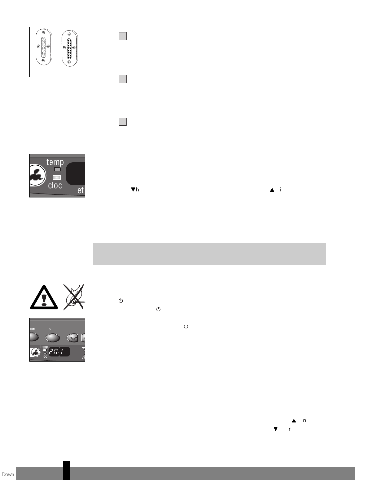
When the indicator light FUEL lights up, it means that there is only fuel left for 10
more minutes. The count-down of the remaining heating time can be seen in the
information display L (Fig. K). Now you have two options:
Eyou remove the fuel tank and refill it outside the living room (section B) or
Eyou push the button EXTENSION S. By pushing this button, the remaining
heating time will extend to 60 minutes. The heater will automatically switch
back to its lowest position. In the display the number 60 will appear, which
will decline to 10. At the arrival of 10, you will hear an alarmsignal every two
minutes, warning you to refill the removable tank. If you do not react, the
heater will extinguish by itself. The heater will also sound a warning signal,
when it switches of. The fuel indicator light will blink, while four lines (--:--)
are blinking in the information display. You can stop this by pressing the
button
M
once more.
Once the heater has used up all its fuel and extinguished, it will take some time,
after the refill, before the heater is completely ready for use again.
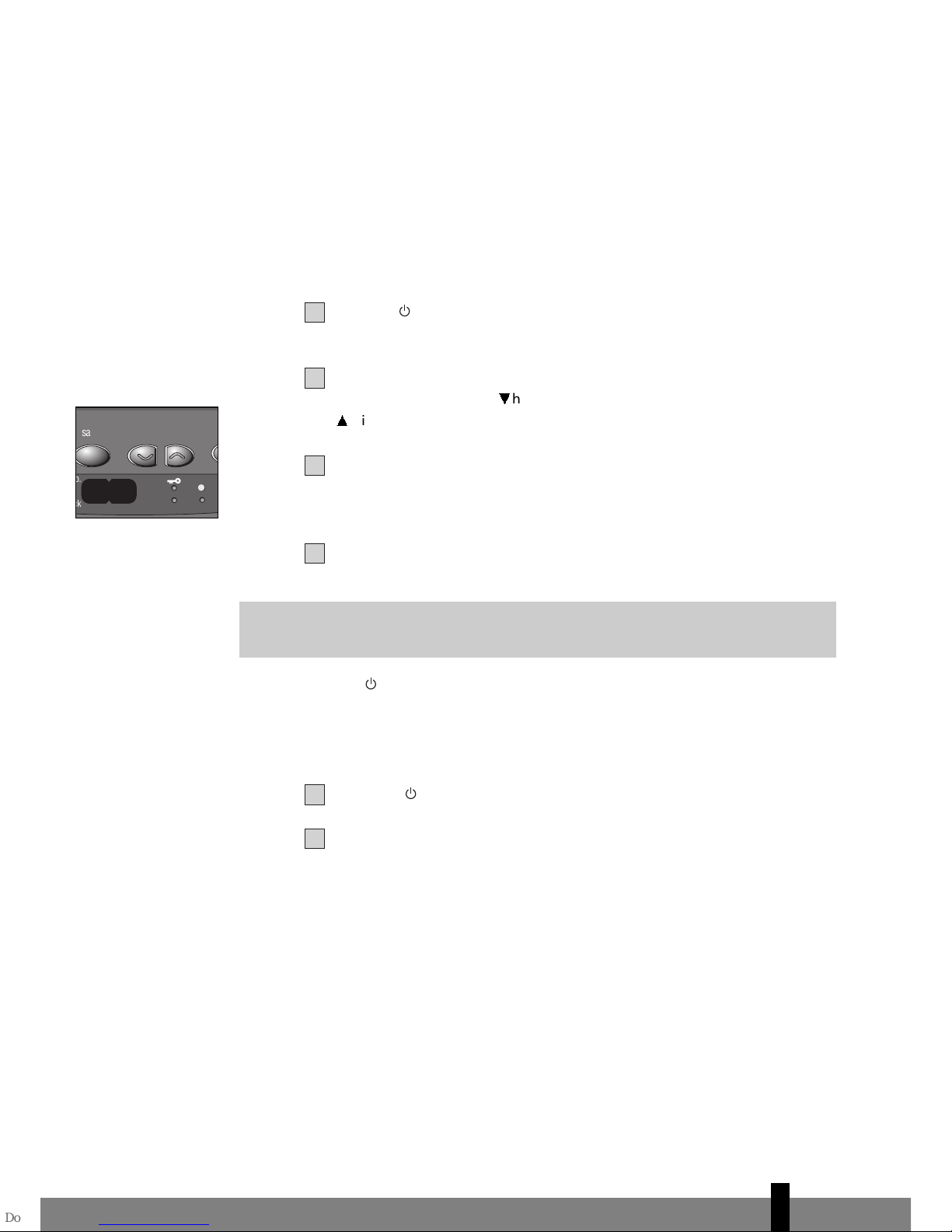
LTHE 'VENT' INDICATOR LIGHT
When there is insufficient ventilation in the room, an intermittent buzzer will be
heard (approximately once each 30 seconds) and the VENT indicator will be lit.
When this signal is given, ensure that the ventilation of the room is improved (e.g.
by opening a door or window a little more), to avoid that the heater shuts off.
When the ventilation of the room is improved, the VENT indicator and buzzer will
be deactivated. When there is still insufficient ventilation, the heater shuts off
automatically. When this occurs, e -1 1 is displayed and the VENT indicator is
blinking. After improving the ventilation of the room (e.g. by opening a door or
window a little more), the heater can be ignited by pushing the on/off button
M
again.
If the indicator light continues blinking after extra ventilation, please contact your
Zibro dealer.
MTHE IONIZER FUNCTION
The ionizer can be activated by pressing the IONIZER button. In this case
negative ions are generated, bringing ‘air vitamins’ to a natural level. This
function can be used when the heater is de-activated also. To switch off the
ionizer function, the IONIZER button should be pressed again.
NMAINTENANCE
Switch off the heater and let it cool down, before you start any maintenance
work. Also disconnect the plug from the mains.
Your Zibro needs hardly any maintenance. It is, however, important that you clean
the air filter cap 8and the vent filter 9with a vacuum cleaner and the grid 2
with a damp cloth, both on a weekly basis. Remove the air filter cap occasionally
(Fig. M) and clean it with soapy water. Prior to reinstallation, make sure that the
air filter cap has fully dried. 4
49
K: When the FUEL
indicator light is lit, the
information display will
show the number of
minutes of fuel left in
the tank.
M
Fuel filter
L: A blinking VENT
indicator light is a sign
that you need extra
ventilation.
20:15
set room
key-lock timer save hour min. extension
temp. timer
fuel
vent.
clock
ion
save
10
e - 1 1
set room
key-lock timer save hour min. extension
temp. timer
fuel
vent.
clock
ion
save
N

☞
Regularly inspect the fuel filter as well:
Remove the removable tank 7from the heater and remove the fuel filter
(Fig. N). Some drops may leak from the filter; keep a cloth at hand.
Remove the dirt by tapping the fuel filter upside-down against a hard surface.
(Never clean it with water!)
Reinstall the fuel filter into the heater.
We recommend that you remove dust and stains in time with a damp cloth, becau-
se otherwise these may cause stains that are hard to remove.
Do not remove any heater components yourself. Always contact your Zibro
dealer for repairs. When the power cord is damaged, it may only be replaced
by an authorised fitter. Use a new cord of the type H05 VV-F.
OSTORAGE (END OF THE HEATING SEASON)
At the end of the heating season, you must store the heater in a dust-free place, if
possible in its original packaging.
Unused fuel cannot be used in the next heating season. We therefore recommend that
you burn up all fuel. If there is still some fuel left, do not throw it away, but dispose of
it in accordance with the local regulations for the disposal of domestic chemical waste.
Always start the new heating season with fresh fuel. When you start re-using the
heater follow the instructions again (starting from section A and as specified).
PTRANSPORTATION
Take the following measures to avoid fuel leakage during the transportation of
the heater:
Let the heater cool down.
Remove the removable tank Gfrom the heater and remove the fuel filter
(refer to Section N, Fig. N). Some drops may leak from the filter; keep a cloth
at hand. Store the fuel filter and the removable tank outside the heater.
Place the transportation cap into the position of the fuel filter (Fig. O).
Press it tight.
Always move the heater in an upright position.
QSPECIFICATIONS
Ignition electrical Dimensions (mm) width 550
Fuel paraffin (including base plate) depth 328
Capacity (kW) max. 4.65 height 445
Capacity (kW) min. 1.45 Accessories manual fuel pump
Suitable space (m3)** 75-190 fuel cap cover, transportation cap
Fuel consumption (l/hr)*0.484 Mains 220V/230V
Fuel consumption (g/hr)*388 -- AC/50 Hz
Burning time per tank (hr)*15.7
Electrical consumption
igniter 320 W
Capacity removable tank (litres) 7.6 continuous 31 W
Weight (kg) 13.5 Fuse rating 250V, 5A
Monitoring of the quality of ventilation (air renewal):
Direct measurement of the CO2level (NDIR CO2-sensor E-Guard ).
* At maximum setting ** Specified values are indicative
4
3
2
1
3
2
1
4
50
transportation cap
O

RWARRANTY PROVISIONS
Your heater comes with a 24-month warranty starting on the date of purchase.
Within this period all defects in material or workmanship will be repaired without
any charge. The following provisions shall apply regarding this warranty:
We expressly dismiss all other claims for damages, including consequential
damages.
Any repairs or replacements of components within the term of warranty will
not result in an extension of the term of warranty.
The warranty shall no longer apply, when the heater has been modified,
non-original parts have been used, or when it is repaired by third parties.
The warranty shall not apply to parts that are subject to normal wear, such as
the burner mat and the manual fuel pump.
The warranty shall only apply, when you present the original, dated proof of
purchase, provided no changes have been made to it.
The warranty shall not apply to damages caused by actions not in compliance
with the Directions for Use, neglect, and the use of an incorrect type of fuel,
or fuel past its use-by date. The use of incorrect fuel can even be dangerous*.
Transportation costs and the risks involved during the transportation of the
heater or heater components shall always be for the account of the purchaser.
In order to avoid unnecessary costs, we recommend that you always read the
’Directions for Use’ carefully first. In case they offer no solution, please take the
heater to your dealer for repair.
* Highly inflammable substances may induce uncontrollable burning, causing flames to break out. Should this
happen, never try to move the heater, but always switch off the heater immediately. In case of emergency you
may use a fire extinguisher, but only a type B extinguisher: a carbon dioxide or powder extinguisher.
10 TIPS FOR SAFE USE
1Make sure that children are always aware of the presence of a burning
heater.
2Do not move the heater when it is burning or still hot. Do not refill nor
service the heater when it is burning or still hot.
3Position the front of the heater at a distance of minimum 1.5 metres
from walls, curtains, and furniture.
4Do not use the heater in dusty rooms. You will not have optimum
burning in such rooms. Do not use the heater in the immediate
surrounding of a bath, a shower or a swimmingpool.
5Switch off the heater, before you leave or go sleeping. Unplug the
heater as well, when you go away for a longer period of time
(e.g. holidays).
6Store and move fuel only in suitable tanks and jerrycans.
7Make sure that the fuel is not exposed to heat or extreme temperature
changes. Always store the fuel in a cool, dry and dark place (sunlight
will affect the quality).
8Never use the heater in places where harmful gasses or fumes may be
present (e.g. exhaust gasses or paint fumes).
9Beware that the grid of the heater becomes hot. If the appliance is
covered there is a risk of fire.
10 Always make sure that there is sufficient ventilation.
Defective electrical devices and batteries must be kept separate from household
waste. Ensure that there is effective recycling where possible. Ask you local council
or dealer for expert advice on recycling.
7
6
5
4
3
2
1
4
51

E E E E E E E E E E E E E E E E E E E E E E E E E
20:15
set room
key-lock timer save hour min. extension
temp. timer
fuel
vent.
clock
ion
save
F
T
D
J
H
K
E
G
A
B
C
RL
QP O MN S
E
I

PVG Traffic avg©060718 man_SRE188E
New 7/07 Printed in Japan
7818001921
DISTRIBUTED IN EUROPE BY PVG INTERNATIONAL b.v.
iÖSTERREICH
PVG Austria VertriebsgmbH
Salaberg 49
3350 HAAG
tel: +43 7434 44867
fax: +43 7434 44868
email: [email protected]
eBELGIË
PVG Belgium NV/SA
Industrielaan 55
2900 SCHOTEN
tel: +32 3 326 39 39
fax: +32 3 326 26 39
email: [email protected]
qSCHWEIZ
PVG Schweiz AG
Salinenstrasse 63
4133 PRATTELN
tel: +41 61 337 26 51
fax: +41 61 337 26 78
email: [email protected]
2DEUTSCHLAND
PVG Deutschland GmbH
Siemensstrasse 31
47533 KLEVE
tel: 0800 - 9427646
fax: +31 (0)412 648 385
email: [email protected]
6DANMARK
Appliance A/S
Blovstroed Teglvaerksvej 3
DK-3450 ALLEROED
tel: +45 70 205 701
fax: +45 70 208 701
email: [email protected]
5ESPAÑA
PVG España S.A.
Pol. Ind. San José de Valderas II
Comunidad ”La Alameda”
C/ Aurora Boreal, 19
28918 LEGANÉS (Madrid)
tel: +34 91 611 31 13
fax: +34 91 612 73 04
email: [email protected]
3FRANCE
PVG France SARL
4, Rue Jean Sibélius
B.P. 185
76410 SOTTEVILLE SOUS LE VAL
tel: +33 2 32 96 07 47
fax: +33 0 820 34 64 84
email: [email protected]
SUOMI
Appliance Finland Oy
Piispantilankuja 6C
02240 ESPOO
tel: +358 9 4390 030
fax: +358 9 4390 0320
email: appliance@appliance-group.com
FFIINN
4UNITED KINGDOM
Scott Brothers Ltd.
The Old Barn, Holly House Estate
Cranage, Middlewich, CW10 9LT UK
tel.: +44 1606 837787
fax: +44 1606 837757
email: [email protected]
>ITALIA
PVG Italy SRL
Via Niccolò Copernico 5
50051 CASTELFIORENTINO (FI)
tel: +39 571 628 500
fax: +39 571 628 504
email: [email protected]
uNORGE
Appliance Norge AS
Vogellunden 31
1394 NESBRU
tel: +47 667 76 200
fax: +47 667 76 201
email: [email protected]
1NEDERLAND
PVG International B.V.
P.O. Box 96
5340 AB OSS
tel: +31 412 694 694
fax: +31 412 622 893
email: [email protected]
9PORTUGAL
Gardena, Lda
Recta da Granja do Marquês
ALGUEIRÃO
2725-596 MEM MARTINS
tel: + 35 21 92 28 530
fax: + 35 21 92 28 536
email: [email protected]
:POLSKA
PVG Polska Sp. z. o. o.
ul. Kościelna 110
26-800 Białobrzegi
tel: +48 48 613 00 70
fax: +48 48 613 00 70
email: pvgpoland@zibro.com
=SVERIGE
Appliance Sweden AB
Sjögatan 6
25225 HELSINGBORG
tel: +46 42 287 830
fax: +46 42 145 890
email: [email protected]
TURKEY
PVG Is›tma Klima So¤utma Ltd.fiti.
Atatürk Cad. No 380 Ak Iflhani Kat 6
35220 Alsancak
IZMIR - TURKEY
tel: + 90 232 463 33 72
fax: + 90 232 463 69 91
email: pvgturkey@zibro.com
TTRR
Table of contents
Other Zibro Heater manuals

Zibro
Zibro R 263 T User manual

Zibro
Zibro R 316 C User manual

Zibro
Zibro R 421 TC User manual

Zibro
Zibro Kamin Champion User manual

Zibro
Zibro Kamin SRE 176 User manual

Zibro
Zibro SRE 260 User manual

Zibro
Zibro SRE 237 E User manual

Zibro
Zibro SRE 150 laser User manual

Zibro
Zibro Laser User manual

Zibro
Zibro R 26 T User manual

Zibro
Zibro SRE 153 User manual

Zibro
Zibro R 611 C User manual

Zibro
Zibro Kamin SRE 166 User manual

Zibro
Zibro R 14 User manual

Zibro
Zibro SRE 168 E User manual

Zibro
Zibro Kamin SRE 177 User manual

Zibro
Zibro SRE 159 E User manual

Zibro
Zibro SRE 237 E User manual

Zibro
Zibro R 31 E User manual

Zibro
Zibro Hybrid E User manual