manuals.online logo
Brands
  1. Home
  2. •
  3. Brands
  4. •
  5. ZIEHL
  6. •
  7. Measuring Instrument
  8. •
  9. ZIEHL MSF 220 SV User manual

ZIEHL MSF 220 SV User manual

date / name 23.02.1999 Wl / Fz Z. Nr.: 1029 0710.1
sheet 1 of 4 T
y
pe: MSF 220 SV
MINIPAN
®
digital panel meters, temperature- and mains controlling,
special purpose instruments for customer requirements www.ziehl.d
e
ZIEHL industrie-elektronik GmbH+Co, Daimlerstr.13, D-74523 Schwäbisch Hall, Tel.: +49 791 504-0, Fax: -56, e-mail: [email protected]
O
Op
pe
er
ra
at
ti
in
ng
g
m
ma
an
nu
ua
al
l
MSF 220 SV
Application
The PTC-resistor trip device MSF 220 SV monitors the winding temperature of machines and
equipment. It signals “early warning" or “malfunction" (switching-off) or switches on a forced
ventilatition as soon as the nominal response temperature (NRT) in the relevant PTC-circuit is
exceeded.
Two PTC-circuits can be connected to this unit. The integrated rise-delay time ensures a
reliable mains voltage build-up.
Function
* 3 PTC resistor circuits, 1 to 6 PTC each (max. cold resistance of circuit 1500Ωeach)
* potential-free contact for switching forced cooling
* potential-free contact for alarm 1
* potential-free contact for alarm 2
* LED´s signal state of relays
* relay K3 picks up time-delayed
Note
Thanks to the delayed switching-on of the error message (approx. 2 s) after the switching-on,
this device is especially suitable where an auxiliary voltage is not available and the secondary
voltage of the monitored transformer is being used. The MSF 200 SV can furthermore be
used advantageously when combining it with operating current releases. In case of malfunction
of the supply voltage or of the relay, there will be no tripping of the alarms. The correct function
can be detected by monitoring the no-contacts of the relays for alarm 1 or 2 (Pins 4 or 5).
Functional description
PTC-circuits in closed-circuit current principle. When the closed-circuit current flows, both output
relays K1, K2 are picked up. Approx. 2 sec. after switching on supply power, relay K3 picks
up time-delayed, closing the contact circuits at terminals 36-14 and 36-24.
When the NRT in the PTC-circuit "VENT" is exceeded, relay K4 picks up. The relay releases
app. 20 minutes after temperature has dropped under the switching point. This ensures a
longer period of cooling.
As soon as the temperature of the early warning has been reached, relay K1 releases
(terminal 36-12 closed), the alarm 1 is given. If the temperature of malfunction is reached, also
relay K2 releases (terminal 36-22 closed). This alarm 2 can be used to switch off the
equipment. If the temperature drops to approx. 5 °C below the temperature of malfunction or
early warning, the relays K1 and K2 are switched on again.
date / name 23.02.1999 Wl / Fz Z. Nr.: 1029 0710.1
sheet 2 of 4 T
y
pe: MSF 220 SV
Technical Data
……………………
Type-Plate
Order number see type plate
Supply voltage Us / frequency on the device
……………………
Tolerance vottage Us AC 0.9...1.1 Us DC 0.85...1.35 Us
Tolerance frequency Us 48...62Hz
PTC-resistor connection 3 x 1...6 PTC in series
Cut-out point 2,8...3,6 kΩ, typ. 3,2 kΩ
Reclosing point 1,8...2,4 kΩ, typ. 2,1 kΩ
Collective resistance of cold sensors ≤1.5 kΩ
Terminal voltage (sensors) ≤2.5 V at ≤250 Ω
≤7.5 V at ≥4 kΩ
Relay output contacts AgCdO
Switching voltage AC max. 400 V DC 110-250 V 0.25 A
Switching current AC max. 8 A DC 60 V 0.5A
Switching power AC max. 1100 VA DC 30 V 1.5 A
Rated continious current Ith AC 6 A DC 24 V 5 A
Rated operational current Ie 2A AC15 400 V 2A DC13 24 V
4A AC15 250V
Prefuse for device and contacts AC: T 4 A DC: F 2 A
Mechanical contact life 5 x 10⁷operations
Electrical contact life 2 x 10⁵operations (at max. switching capacity)
Factor of reduction at cos = 0.4 0.6 x max. switching capacity
Switching-on delay app. 2 sec.
Testing conditions VDE 0660 / VDE 0160
Rated insulation voltage AC 250 V
Isolation VDE 110 / Gr. C
Transformer VDE 0550
Test voltage between supply voltage,
relay outputs and sensor side 2.5 kV
On period 100 %
max. ambient temperature -20 ... +55 °C
Climatic category F (according to DIN 40 040)
Housing: design S-12, plug-in housing
Dimensions (H x W x D) 82 x 42 x 121 mm
Line connection 12-pole, max. 2 x 1.5 mm2each
Protection Housing IP 40
Protection contacts IP 20
Panel inclination any
Mounting snapable on 35 mm standard rail according to DIN
or assembly with scrwes M 4
Weight app. 250 g
date / name 23.02.1999 Wl / Fz Z. Nr.: 1029 0710.1
sheet 3 of 4 T
y
pe: MSF 220 SV
Installation - Putting into operation
The plug base can be mounted either with
* 35 mm mounting rail according to DIN 50 002 or
* M4 screws
Wiring directly to plug base
* Connect wires as per wiring scheme
* Plug in electronics and fix with knurled screw
Attention!
Do not plug in device alive nor detach it from socket.
When installing the device into the switch-gear cabinet, please observe the max.
admissible temperature. Care for both sufficient clearance to other devices or
sources of heat or enough forced draught. Generally recommended mininum
clearance: 2 cm.
Before switching on make sure that the operational voltage Us of the lateral type
plate and the mains voltage are the same.
* Apply mains voltage to terminals 11 and 12.
* When device is ready for operation, relays “ALARM1” and “ALARM2” switch on
immediately, the LED’s are off. After approx. 2 s. relay “ON” picks up, terminals 3 -
4, 3 - 5 are connected.
* Relay "VENT" picks up, as soon as the input at terminal 7, 10 becomes high-resistive.
* Relay "VENT" releases 20 min. after the input at terminal 7, 10 becomes low-resistive.
* Relay “ALARM1” releases as soon as the input at terminal 8, 10 becomes high-
resistive.
* Relay “ALARM2” releases as soon as the input at terminal 9, 10 becomes high-
resistive.
* Relay “ALARM1”, “ALARM2” pick up as soon as the inputs at terminals 8, 10 ; 9,
10 become low-resistive.
* Relay “ON” releases first, as soon as the supply voltage is switched off.
Trouble-shooting and remedies
* Relays are not switched on.
Check whether supply voltage Usat terminal 11, 12 is available and corresponds to
the voltage indicated on the lateral type plate of the device.
* LED´s light up continuously.
Check whether PTC’s at terminals 7-10, 8-10 and 9-10 are connected correctly. Both
PTC’s must be connected and low-resistive.
Attention! Check PTC’s only with measuring voltages of < 2.5 V.
* In case of any other malfunctions, replace device and send it in together with a
description of the occurred malfunction.
date / name 23.02.1999 Wl / Fz Z. Nr.: 1029 0710.1
sheet 4 of 4 T
y
pe: MSF 220 SV
Wiring Scheme
A2 A1
11 =
1
22
2
24
4 5 7 8 9 10 11 12
US
~~ +-
12
6
14
3
ALARM
1
ALARM 2
ON
47
48 VENT.
36
35
ALARM 1
VENT.
ALARM
2
21
Design S 12
5
104,5
82
36
23,5
AA
AA
AA
38
34
80
61
5
17,5
7,5
41,5
17 41 10
82
1
12345 7689101112
11,5
16
5
2
3
1
14
27,5
116
AA
AA
41,5
Base
1
2
3
Cable bushing
Mounting bore-hole
Unlatching
(only with rail-mounting)
2
6 Jacks for coding-pins
1

Other ZIEHL Measuring Instrument manuals

ZIEHL MSF220K User manual

ZIEHL

ZIEHL MSF220K User manual

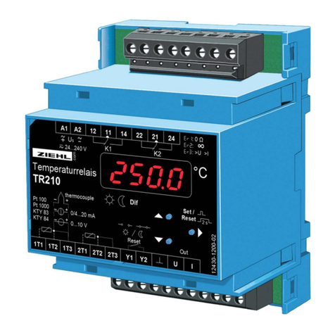
ZIEHL MINIPAN TR210 User manual

ZIEHL

ZIEHL MINIPAN TR210 User manual

ZIEHL TR660IP User manual

ZIEHL

ZIEHL TR660IP User manual

ZIEHL MINIPAN NS43V User manual

ZIEHL

ZIEHL MINIPAN NS43V User manual

ZIEHL MINIPAN 300 User manual

ZIEHL

ZIEHL MINIPAN 300 User manual

ZIEHL TR640IP User manual

ZIEHL

ZIEHL TR640IP User manual

ZIEHL UFR1001E User manual

ZIEHL

ZIEHL UFR1001E User manual

ZIEHL UFR1001 User manual

ZIEHL

ZIEHL UFR1001 User manual

ZIEHL TMU104V User manual

ZIEHL

ZIEHL TMU104V User manual

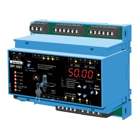
ZIEHL SPI1021 User manual

ZIEHL

ZIEHL SPI1021 User manual

Popular Measuring Instrument manuals by other brands

Renishaw LP2 Installation and user guide

Renishaw

Renishaw LP2 Installation and user guide

IBA ibaBM-DPM-S-64 manual

IBA

IBA ibaBM-DPM-S-64 manual

H2flow FLOWVIS operating manual

H2flow

H2flow FLOWVIS operating manual

TESTO 206 instruction manual

TESTO

TESTO 206 instruction manual

TPI A771 instruction manual

TPI

TPI A771 instruction manual

GYS GYSMETER 052093 manual

GYS

GYS GYSMETER 052093 manual

Blue-White APNTU quick start guide

Blue-White

Blue-White APNTU quick start guide

PROSES Aqua-Boy manual

PROSES

PROSES Aqua-Boy manual

GE 3300 installation manual

GE

GE 3300 installation manual

Kromek GR1-A user guide

Kromek

Kromek GR1-A user guide

ADTEK CPM-12D manual

ADTEK

ADTEK CPM-12D manual

Emerson Micro Motion 7829 Visconic Series Product data sheet

Emerson

Emerson Micro Motion 7829 Visconic Series Product data sheet

Santec PEM-340 Operation manual

Santec

Santec PEM-340 Operation manual

Kanomax 3443 Operation manual

Kanomax

Kanomax 3443 Operation manual

GPI GM50 series instruction manual

GPI

GPI GM50 series instruction manual

YOKOGAWA PR300 Startup manual

YOKOGAWA

YOKOGAWA PR300 Startup manual

Seametrics FT420 manual

Seametrics

Seametrics FT420 manual

Parker SensoControl Serviceman SCM-150 Series operating instructions

Parker

Parker SensoControl Serviceman SCM-150 Series operating instructions

manuals.online logo
manuals.online logoBrands
  • About & Mission
  • Contact us
  • Privacy Policy
  • Terms and Conditions

Copyright 2025 Manuals.Online. All Rights Reserved.