UFR1001E 12420-0751-13 Page
/ 8 www.ziehl.de
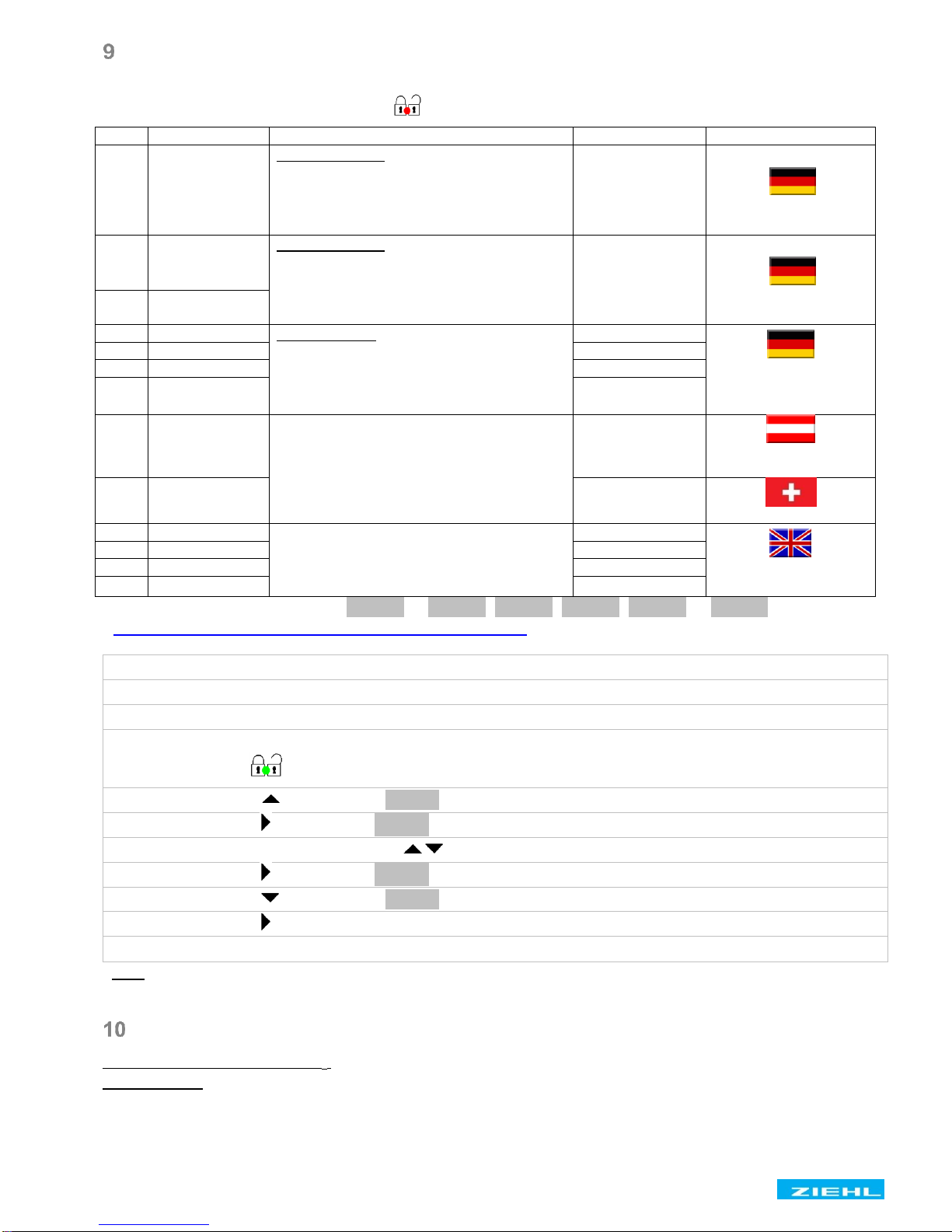
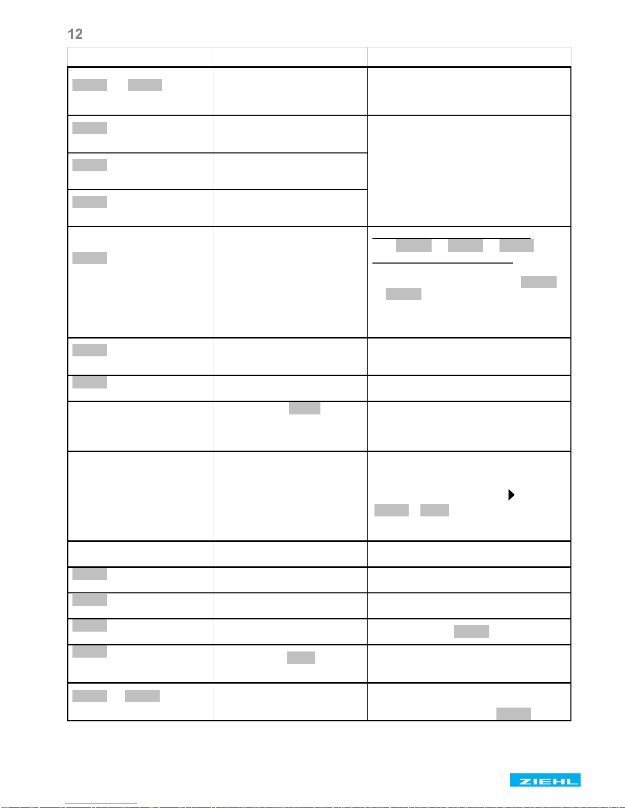
Troubleshooting
8EEEE8or 8-EEE8appears
in the display
Measured voltage, frequency
or the vector shift is too large
or too small
Consider the measuring range
8Err48
appears in the display
Tolerance error, internal
measurement value deviation
of both channels
Perform a reset →
interrupt the control supply voltage
for >5 s *
8Err58
appears in the display
Error internal regulation
8Err68
appears in the display
Communication error internal
interface
8Err78appears in the
display even after 2
automatic repeated trials of
switching on + LED K1
and/or K2 is lightning
Error feedback contacts,
switches not connected
correctly or broken or
switches are controlled from
other device
Feedback contacts not connected
- set 8rel .8→8trel.8→8off8
Feedback contacts connected
- check the correct connection
- Adjust the turn-on time under 8rel .8
→8trel.8greater then the switch-on
time of the switcher
- Perform a reset →press Set/Reset
for >2 s
8Err88
appears in the display
Hysteresis error:
overlapping of the release
points
Upper threshold value must be higher
than the lower threshold value, check the
threshold values
8Err98
appears in the display
Reset to factory settings, see “Program
setup” *
A time expires in the display
If a OFF-delay 8dof 8is
active, the time runs down in
the display (the shortest one
first)
Wait until the time is complete
(depending on the setting, several times
may elapse one after the other)
Device cannot be configured
/ only the threshold values
can be configured
Code lock / Sealing activated
When having problems with the code
lock (Pin forgotten), the lock can be
deactivated and the pin can be reset to
504 , by pressing the button until
8Code8/ off8is shown in the display,
while switching on the control supply
voltage
Implausible voltage values
Pr selected with N, but N not
connected
Select Pr without N or connect N
8Loc 8
appears in the display
8Code8
appears in the display
8stby8appears in the
display
Standbymode, E1-E2 closed
8Al 8and LED Q3 (f>) is
on, reading value in good
range
hysteresis for 8F, 8
incorrectly
Ceck hysteresis for reset point
50,05 Hz
8noY18or 8noY28appears
in the display
Feedback contact not
connected or switch does not
switch
Check the connection and function of the
switch.
Its normal in Pr2 at Test 2 8noY28.
*If the error cannot be patched by a reset, send back to factory for repair.