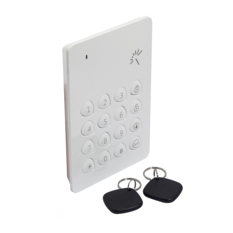
ZKTeco VT07-B01-W User manual

Product Name and Model Number User Manual
P a g e |1Copyright©2020 ZKTECO CO., LTD. All rights reserved.
Thank you for choosing our product. Please read the instructions carefully
before operation. Follow these instructions to ensure that the product is
functioning properly. The images shown in this manual are for illustrative
purposes only.
For further details, please visit our Company’s website
www.zkteco.com.
-W-W-W

User Manual
P a g e | 2 Copyright©2022 ZKTECO CO., LTD. All rights reserved.
relating to the use of the information contained in or referenced by this manual, even if ZKTeco has been
advised of the possibility of such damages.
This manual and the information contained therein may include technical, other inaccuracies or
typographical errors. ZKTeco periodically changes the information herein which will be incorporated into
new additions/amendments to the manual. ZKTeco reserves the right to add, delete, amend or modify the
information contained in the manual from time to time in the form of circulars, letters, notes, etc. for better
operation and safety of the machine/unit/equipment. The said additions or amendments are meant for
improvement /better operations of the machine/unit/equipment and such amendments shall not give any
right to claim any compensation or damages under any circumstances.
ZKTeco shall in no way be responsible (i) in case the machine/unit/equipment malfunctions due to any
non-compliance of the instructions contained in this manual (ii) in case of operation of the
machine/unit/equipment beyond the rate limits (iii) in case of operation of the machine and equipment in
conditions different from the prescribed conditions of the manual.
The product will be updated from time to time without prior notice. The latest operation procedures and
relevant documents are available on http://www.zkteco.com.
If there is any issue related to the product, please contact us.
ZKTeco Headquarters
Address ZKTeco Industrial Park, No. 32, Industrial Road,
Tangxia Town, Dongguan, China.
Phone +86 769 - 82109991
Fax +86 755 - 89602394
For business related queries, please write to us at: sales@zkteco.com.
To know more about our global branches, visit www.zkteco.com.

User Manual
P a g e | 3 Copyright©2022 ZKTECO CO., LTD. All rights reserved.
About the Company
ZKTeco is one of the world’s largest manufacturer of RFID and Biometric (Fingerprint, Facial, Finger-vein)
readers. Product offerings include Access Control readers and panels, Near & Far-range Facial Recognition
Cameras, Elevator/floor access controllers, Turnstiles, License Plate Recognition (LPR) gate controllers and
Consumer products including battery-operated fingerprint and face-reader Door Locks. Our security
solutions are multi-lingual and localized in over 18 different languages. At the ZKTeco state-of-the-art
700,000 square foot ISO9001-certified manufacturing facility, we control manufacturing, product design,
component assembly, and logistics/shipping, all under one roof.
The founders of ZKTeco have been determined for independent research and development of biometric
verification procedures and the productization of biometric verification SDK, which was initially widely
applied in PC security and identity authentication fields. With the continuous enhancement of the
development and plenty of market applications, the team has gradually constructed an identity
authentication ecosystem and smart security ecosystem, which are based on biometric verification
techniques. With years of experience in the industrialization of biometric verifications, ZKTeco was
officially established in 2007 and now has been one of the globally leading enterprises in the biometric
verification industry owning various patents and being selected as the National High-tech Enterprise for 6
consecutive years. Its products are protected by intellectual property rights.
About the Manual
This manual introduces the operations of VT07-B01-W.
All figures displayed are for illustration purposes only. Figures in this manual may not be exactly consistent
with the actual products.
Features and parameters with ★are not available in all devices.

User Manual
P a g e | 4 Copyright©2022 ZKTECO CO., LTD. All rights reserved.
Document Conventions
Conventions used in this manual are listed below:
GUI Conventions
For Software
Convention Description
Bold font Used to identify software interface names e.g., OK,Confirm,Cancel.
>Multi-level menus are separated by these brackets. For example, File > Create >
Folder.
For Device
Convention Description
< > Button or key names for devices. For example, press <OK>.
[ ] Window names, menu items, data table, and field names are inside square
brackets. For example, pop up the [New User] window.
/Multi-level menus are separated by forwarding slashes. For example,
[File/Create/Folder].
Symbols
Convention Description
This represents a note that needs to pay more attention to.
The general information which helps in performing the operations faster.
The information which is significant.
Care taken to avoid danger or mistakes.
The statement or event that warns of something or that serves as a cautionary
example.

User Manual
P a g e | 5 Copyright©2022 ZKTECO CO., LTD. All rights reserved.
Table of Contents
1APPEARANCE ..............................................................................................................................................7
2INSTALLATION SET-UP .............................................................................................................................. 8
2.1 INSTALLATION ENVIRONMENT.....................................................................................................................................................................8
2.2 INSTALLATION STEPS....................................................................................................................................................................................... 8
3CONNECTION DIAGRAM ..........................................................................................................................10
4MAIN MENU..............................................................................................................................................11
5LIVE VIDEO SETTING ................................................................................................................................13
5.1 OUTDOOR STATION MONITOR..................................................................................................................................................................13
5.2 IPC MONITOR.....................................................................................................................................................................................................13
5.3 LIVE VIDEO..........................................................................................................................................................................................................14
5.3.1 REAL-TIME VIDEO OF OUTDOOR STATION........................................................................................................................................................... 14
5.3.2 REAL-TIME VIDEO OF IPC MONITOR.........................................................................................................................................................................15
6CALL LOG ..................................................................................................................................................16
6.1 ALL CALL LOGS .................................................................................................................................................................................................16
6.2 MISSED CALL LOGS.........................................................................................................................................................................................17
7NEWS SETTINGS ....................................................................................................................................... 18
8NETWORK SETTINGS ................................................................................................................................19
8.1 WIRED NETWORK.............................................................................................................................................................................................19
8.2 WIRELESS NETWORK...................................................................................................................................................................................... 20
9SYSTEM SETTINGS ................................................................................................................................... 22
9.1 SOUND SETTINGS............................................................................................................................................................................................ 22
9.1.1 DO NOT DISTURB PLAN .................................................................................................................................................................................................23
9.2 DISPLAY SETTINGS .......................................................................................................................................................................................... 24
9.3 ADVANCED SETTINGS ....................................................................................................................................................................................25
9.3.1 MODIFY PASSWORD.......................................................................................................................................................................................................26
9.3.2 DEVICE MANAGEMENT..................................................................................................................................................................................................26


User Manual
P a g e | 6 Copyright©2022 ZKTECO CO., LTD. All rights reserved.
9.3.3 LOCAL SETTING.................................................................................................................................................................................................................29
9.3.4 TIME SETTING.....................................................................................................................................................................................................................30
9.3.5 STORAGE MANAGE..........................................................................................................................................................................................................31
9.3.6 NETWORK MANAGE........................................................................................................................................................................................................32
9.4 SYSTEM INFORMATION.................................................................................................................................................................................33
9.5 RESET SETTINGS............................................................................................................................................................................................... 33
10 MAKE A CALL ..........................................................................................................................................35
10.1 SET THE COMMUNICATION ADDRESS..................................................................................................................................................35
10.2 ADDING OUTDOOR STATION...................................................................................................................................................................36
10.3 MAKE A CALL ON THE DEVICE................................................................................................................................................................. 36
APPENDIX ....................................................................................................................................................39
FCC WARNING..........................................................................................................................................................................................................39
ECO-FRIENDLY OPERATION............................................................................................................................................................................... 40

User Manual
P a g e | 7 Copyright©2022 ZKTECO CO., LTD. All rights reserved.
1Appearance

User Manual
P a g e | 8 Copyright©2022 ZKTECO CO., LTD. All rights reserved.
2Installation Set-up
2.1 Installation Environment
2.2 Installation Steps
Make sure that the device is installed as per the installation instructions. Otherwise, you will bear any
consequence resulting from your actions.
The device supports two installation methods: wall-mounted installation and desktop installation. Users
can choose according to actual needs.
Mode 1: Wall-mounted Installation
Step1: Find a suitable indoor installation location, the recommended installation height is 59.1 inches
(1.5m), which can be adjusted as needed.
Step2: Attach the mounting template stickers to the wall and drill holes, then fix the back plate on the wall
with the wall mounting screws.
Step3: Finally, push the device into the back plate and secure it to the back plate.

User Manual
P a g e | 9 Copyright©2022 ZKTECO CO., LTD. All rights reserved.
Mode 2: Desktop Installation
Step1: Take out the device and the bracket from the box.
Step2: Put the white bracket rubber sleeve on the bottom of the bracket.
Step3: Finally, insert the bracket into the mounting slot behind the device.

User Manual
P a g e | 10 Copyright©2022 ZKTECO CO., LTD. All rights reserve
d.
3Connection Diagram
Notes:
1. VT07-B01-W , Video intercom device and camera are connected through out the network cable.
2. In LAN, the IP addresses of all devices must be in the same network segment. See figure above for an
example.
-W

User Manual
P a g e | 11 Copyright©2022 ZKTECO CO., LTD. All rights reserve
d.
4Main Menu
After powering on the device, it enters the main interface as shown below.
When you tap the icon to turn on the Do Not Disturb mode, the screen is shown below. A red bar
will appear at the bottom of the screen. Prompts you that the Do Not Disturb feature is turned on.

User Manual
P a g e | 12 Copyright©2022 ZKTECO CO., LTD. All rights reserve
d.
Function Description
Menu Descriptions
Do Not Disturb mode function button. Once turned on, when the outdoor station
calls, the indoor station has no response and no record, and the priority is higher
than the "Do Not Disturb Plan" in the setting interface. Applies to this device only.
Live Video To view the real-time video of the outdoor station and the real-time video of the IPC
bound to it, and the real-time video of other IPC.
Call Log To view the answered and missed call logs.
Setting To set parameters related to the system, such as sound settings, display settings, advanced
settings, system information viewing and restore default/upgrade.
News To view the video information such as call record, manual record and snap.
Network To set the relevant parameters of Network.
Status Icons
Status Icon Name Description
Ethernet
Indicates that the Ethernet connection has been established.
Indicates that the Ethernet is disconnected.
TF Card Indicates that the TF card has been inserted.
Wi-Fi signal Indicates that the Wi-Fi is connected normally.

User Manual
P a g e | 13 Copyright©2022 ZKTECO CO., LTD. All rights reserve
d.
5Live Video Setting
5.1 Outdoor Station Monitor
Tap Live Video on the main menu to enter the Outdoor Station Monitor interface. The added Outdoor
Station will be displayed on the interface. Note: The user can customize the position name through the
path Setting > Advanced Setting > Device Manage > +Add > Position.
5.2 IPC Monitor
Tap Live Video on the main menu. Then tap icon on the Outdoor Station Monitor interface. The
added IPC will be displayed on the interface. The user can customize the position name.

User Manual
P a g e | 14 Copyright©2022 ZKTECO CO., LTD. All rights reserve
d.
5.3 Live Video
5.3.1 Real-time Video of Outdoor Station
Select an outdoor station on the Outdoor Station Monitor interface to enter the screen. The screen is
shown below.
Function Description
Function Descriptions
When the monitoring countdown ends, exit the current interface. Clicking the
"Monitor Countdown" icon before the countdown ends will reset the countdown.
Can be modified via Setting > Advanced Setting > Local Setting > Call
Countdown path.
After the countdown is over, the indoor station automatically hangs up. If you click
the countdown icon again within the timer, the countdown will be reset and the
intercom will continue. If you click the icon again, the call is interrupted.
When set to unlimited, the intercom can continue until the call is manually hung up
or the outdoor station hangs up.
Window 1: The default is the outdoor station monitoring screen.
Window 2/3/4: The IPC video monitoring screen bound to the outdoor station
Split screen mode: Tap to switch between 4 Split Screen and 1 Split Screen.
Used for manual snapshots. Click to capture the current video image.
When the screen is 1 split screens, all windows are available for snapshotting.
When the screen is 4 split screens, only window 1 is available for snapshotting.

User Manual
P a g e | 15 Copyright©2022 ZKTECO CO., LTD. All rights reserve
d.
Used for manual recording.
Click the icon to start audio/video recording, and stop recording until the countdown
ends. Or click the countdown icon during the countdown time to continue recording until
the time ends.
If the monitoring countdown is set to unlimited, it will record according to the set
"Maximum Video Recording Time" (please set the maximum recording time in Setting >
Advanced Setting > Local Setting), and stop recording when it reaches the set time, and
continue monitoring until manually exit.
In both 4 split screen and 1 split screen, only windows 1 and 2 can record.
Split screen mode:
4 Split Screen 1 Split Screen
5.3.2 Real-time Video of IPC Monitor
Select an IPC monitor on the IPC Monitor interface to enter the screen. The screen is shown below.
Only support real-time monitoring, manual capture, manual recording function, the function of the same
outdoo station real-time video.

User Manual
P a g e | 16 Copyright©2022 ZKTECO CO., LTD. All rights reserve
d.
6Call Log
6.1 All call logs
Tap Call Log on the Main Menu to enter the All Call list screen. As shown below.
Select a call log in the list to enter the call playback screen. As shown below.
Function Descriptions
Return to the previous menu.
Delete the current call log.
Turns on/off the sound of the current call log.
Play/pause the current call log.
Play the last call log.
Play the next call log.

User Manual
P a g e | 17 Copyright©2022 ZKTECO CO., LTD. All rights reserve
d.
6.2 Missed call logs
Tap Call Log >icon to enter the missed call list screen. As shown below.
Select a missed call log in the list to enter the call playback screen. The interface is the same as that of the
call log, and will not be repeated here.

User Manual
P a g e | 18 Copyright©2022 ZKTECO CO., LTD. All rights reserve
d.
7News Settings
Here users can view some video information such as call logs, manual logs and snapshots.
Tap News on the Main Menu interface. Tap icon to enter the video information interface. As shown
below.
Function Description
Menu Descriptions
Call Record Displays all received and missed call recordings as the same recording as the call log
recording.
Manual Record Manually recorded footage during real-time video surveillance.
Snap Live video interface manually captures images. Page turning is not supported.

User Manual
P a g e | 19 Copyright©2022 ZKTECO CO., LTD. All rights reserve
d.
8Network Settings
When the indoor station needs to communicate with the outdoor station or IPC through Ethernet, you
need to configure the network settings and ensure that all the devices are connected to the same network
segment.
Tap Network on the Main Menu to enter the network setting screen.
8.1 Wired Network
Tap icon on the Network Setting screen to enter the wired network setting screen. As shown below.
Function Description
Function Descriptions
IP Type
Select the way to enter the IP address, there are Static and DHCP options. If Static is
enabled, the IP address can be set manually. Dynamic Host Configuration Protocol,
which is to dynamically allocate the IP addresses for clients via server.
IP Address The default IP address is 192.168.1.201. It can be modified according to the network
availability.
Subnet Mask The default Subnet Mask is 255.255.255.0. It can be modified according to the
network availability.
DNS The default DNS address is 0.0.0.0. It can be modified according to the network
availability.
Gateway The default Gateway address is 0.0.0.0. It can be modified according to the network
availability.

User Manual
P a g e | 20 Copyright©2022 ZKTECO CO., LTD. All rights reserve
d.
Remark:
A direct connection to the local area network can be used. Connect the indoor station and the outdoor
station directly through the network cable, and the outdoor station can preview, record, and talk normally
in the indoor station.
8.2 Wireless Network
Tap icon on the Network Setting screen. Settings interface to configure the Wi-Fi settings.
Wi-Fi is enabled in the device by default. Toggle the button to enable or disable Wi-Fi.
Once the Wi-Fi is turned on, the device searches for the available WIFI within the network range.
Choose the required Wi-Fi name from the available list and input the correct password in the
password interface, and then select Save to confirm.
Table of contents
Other ZKTeco RFID System manuals

ZKTeco
ZKTeco FaceKiosk-H13 User manual

ZKTeco
ZKTeco TSP-4 Series User manual

ZKTeco
ZKTeco Green Label G4L User manual

ZKTeco
ZKTeco OP-200 User manual

ZKTeco
ZKTeco KF1000-U User manual

ZKTeco
ZKTeco SC800 User manual

ZKTeco
ZKTeco SpeedFace-V5L User manual

ZKTeco
ZKTeco GL300 User manual

ZKTeco
ZKTeco SpeedFace-V5L-RFID User manual

ZKTeco
ZKTeco ProlD Series User manual