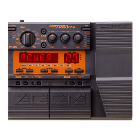
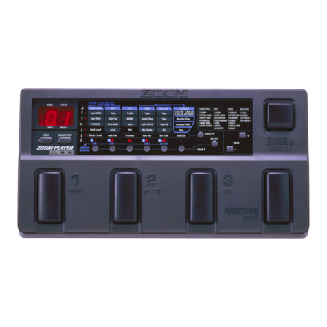
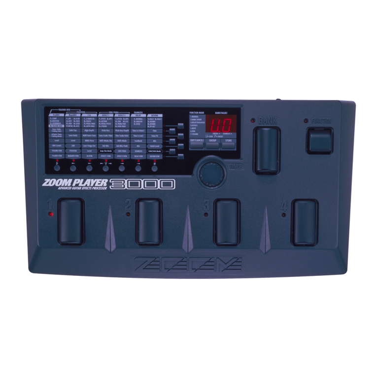
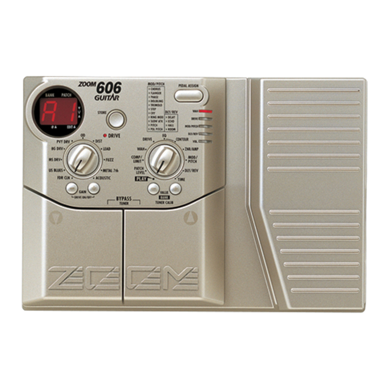
Zoom B9.1ut User manual

Operation Manual
©ZOOM Corporation
Reproduction of this manual, in whole or in part, by any means,
is prohibited.
0804B9E.indb10804B9E.indb1 08.4.2510:57:10AM08.4.2510:57:10AM

SAFETY PRECAUTIONS
In this manual, symbols are used to highlight warnings
and cautions for you to read so that accidents can be
prevented. The meanings of these symbols are as follows:
This symbol indicates explanations about extremely
dangerous matters. If users ignore this symbol and
handle the device the wrong way, serious injury or
death could result.
This symbol indicates explanations about dangerous
matters. If users ignore this symbol and handle the
device the wrong way, bodily injury and damage to
the equipment could result.
Please observe the following safety tips and precautions to
ensure hazard-free use of the B9.1ut
Power requirements
• Be sure to use only the AC adapter which is
supplied with the B9.1ut. The use of any other
adapter may lead to malfunction and damage and
pose a fire hazard or other safety hazard.
• Connect the AC adapter only to an AC outlet that
supplies the rated voltage required by the adapter.
• When disconnecting the AC adapter from the AC
outlet, always grasp the plug and do not pull at
the cable.
• During lightning or when not using the unit for
an extended period, disconnect the AC adapter
from the AC outlet.
• Do not pinch the power cord, bend it forcedly, or
place heavy objects on the power cord.
Environment
To prevent the risk of fire, electric shock
or malfunction, avoid using your B9.1ut in
environments where it will be exposed to:
• Extreme temperatures
• Heat sources such as radiators or stoves
• High humidity or moisture
• Excessive dust or sand
• Excessive vibration or shock
Keep a minimum distance of 5 cm around the unit
for sufficient ventilation.
Do not impede the ventilation openings with
objects such as newspapers or curtains.
Handling
• Never place objects filled with liquids, such as
vases, on the B9.1ut since this can cause electric
shock.
• Do not place naked flame sources, such as lighted
candles, on the B9.1ut since this can cause fire.
• The B9.1ut is a precision instrument. Do not exert
undue pressure on the keys and other controls.
Also take care not to drop the unit, and do not
subject it to shock or excessive pressure.
• Take care that no foreign objects (coins or pins
etc.) or liquids can enter the unit.
Connecting cables and input and output jacks
You should always turn off the power to the
B9.1ut and all other equipment before connecting
or disconnecting any cables. Also make sure to
disconnect all connection cables and the power
cord before moving the B9.1ut.
Alterations
Never open the case of the B9.1ut or attempt to
modify the product in any way since this can result
in damage to the unit.
Volume
Do not use the B9.1ut at a loud volume for a long
time since this can cause hearing impairment.
Usage Precautions
Electrical interference
For safety considerations, the B9.1ut has been designed
to provide maximum protection against the emission
of electromagnetic radiation from inside the device,
and protection from external interference. However,
equipment that is very susceptible to interference or that
emits powerful electromagnetic waves should not be
placed near the B9.1ut, as the possibility of interference
cannot be ruled out entirely.
With any type of digital control device, the B9.1ut
included, electromagnetic interference can cause
malfunctioning and can corrupt or destroy data. Care
should be taken to minimize the risk of damage.
Cleaning
Use a soft, dry cloth to clean the B9.1ut. If necessary,
slightly moisten the cloth. Do not use abrasive cleanser,
wax, or solvents (such as paint thinner or cleaning
alcohol), since these may dull the finish or damage the
surface.
Please keep this manual in a convenient place for
future reference.
* MIDI is a registered trademark of Association of
Musical Electronics Industry(AMEI).
2ZOOM B9.1ut
Safety Precautions / Usage Precautions
0804B9E.indb20804B9E.indb2 08.4.2510:57:10AM08.4.2510:57:10AM

3
ZOOM B9.1ut
Contents
* Windows, Windows XP, and Windows Vista are registered trademarks of Microsoft Corporation.
* Macintosh is a registered trademark of Apple, Inc..
* All other trademarks, product names, and company names mentioned in this document are the property
of their respective owners.
* Manufacturer names and product names mentioned in this document are trademarks or registered
trademarks of their respective owners. The names are used only to illustrate sonic characteristics and do
not indicate any affiliation with ZOOM CORPORATION.
Safety Precautions / Usage Precautions . . . . . 2
Features . . . . . . . . . . . . . . . . . . . . . . . . . . . . . . . . 4
Terms Used in This Manual . . . . . . . . . . . . . . . . 5
Controls and Functions . . . . . . . . . . . . . . . . . . . 6
Getting Connected . . . . . . . . . . . . . . . . . . . . . . . 8
Power-On . . . . . . . . . . . . . . . . . . . . . . . . . . . . . . . 9
Quick Guide 1 (Manual Mode/Play Mode
Operation) . . . . . . . . . . . . . . . . . . . . . . . . . . . . 10
Quick Guide 2 (Edit Mode/Store Mode
Operation) . . . . . . . . . . . . . . . . . . . . . . . . . . . . 12
Switching Modules On and Off (Manual Mode)
. . . . . . . . . . . . . . . . . . . . . . . . . . . . . . . . . . . . . . 14
Panel display . . . . . . . . . . . . . . . . . . . . . . . . . . . . 14
Selecting patches . . . . . . . . . . . . . . . . . . . . . . . . 14
Turning a module on and off . . . . . . . . . . . . . . . . 15
Adjusting the sound . . . . . . . . . . . . . . . . . . . . . . . 16
Using the Accelerator . . . . . . . . . . . . . . . . . . . . . 17
Selecting Patches for Playing (Play Mode) . . 18
Using the Tuner (Bypass/Mute Mode) . . . . . . 20
Using the chromatic tuner . . . . . . . . . . . . . . . . . . 20
Using the bass tuner . . . . . . . . . . . . . . . . . . . . . . 21
Changing the Sound of a Patch
(Edit Mode) . . . . . . . . . . . . . . . . . . . . . . . . . . . 23
Patch configuration . . . . . . . . . . . . . . . . . . . . . . . 23
Basic edit mode steps . . . . . . . . . . . . . . . . . . . . . 23
Changing a patch name . . . . . . . . . . . . . . . . . . . . 26
Storing Patches and Banks (Store Mode) . . . 27
Storing/swapping patches . . . . . . . . . . . . . . . . . . 27
Storing/swapping banks . . . . . . . . . . . . . . . . . . . 28
Returning patches to factory default condition
. . . . . . . . . . . . . . . . . . . . . . . . . . . . . . . . . . . . . . . 29
Using the Expression Pedal . . . . . . . . . . . . . . 30
About the expression pedal . . . . . . . . . . . . . . . . . 30
Assigning control targets to the expression
pedal . . . . . . . . . . . . . . . . . . . . . . . . . . . . . . . . . 31
Adjusting the expression pedal . . . . . . . . . . . . . . 33
Using an external expression pedal . . . . . . . . . . 34
Adjusting the expression pedal torque. . . . .35
Using the Foot Switches. . . . . . . . . . . . . . . . . . 36
Making settings for function foot switches . . . . . 36
Assigning modules to foot switches 1 – 4 . . . . . . 38
Specifying the tempo for a patch . . . . . . . . . . . . 38
Using the Effect Loop . . . . . . . . . . . . . . . . . . . 40
MIDI Usage Examples . . . . . . . . . . . . . . . . . . . 42
What you can do with MIDI . . . . . . . . . . . . . . . . . 42
Selecting the MIDI channel . . . . . . . . . . . . . . . . . 42
Sending and receiving patch switching
information via MIDI (program change). . . . . . . 43
Sending and receiving pedal/switch/key
operation information via MIDI
(control change) . . . . . . . . . . . . . . . . . . . . . . . . . 46
Sending pedal synth playing information via
MIDI (note on/note off) . . . . . . . . . . . . . . . . . . . 49
Sending and receiving B9.1ut patch data
via MIDI. . . . . . . . . . . . . . . . . . . . . . . . . . . . . . . 50
Other Functions . . . . . . . . . . . . . . . . . . . . . . . . 52
Using the ARRM function . . . . . . . . . . . . . . .52
Using the sound-on-sound function . . . . . . . . . . 54
Using the pedal synth function . . . . . . . . . . . . . . 55
Using the B9.1ut as audio interface for
a computer . . . . . . . . . . . . . . . . . . . . . . . . .57
Muting the direct output when using
a USB connection . . . . . . . . . . . . . . . . . . . . . . . 58
Changing the default reference pitch of
the tuner . . . . . . . . . . . . . . . . . . . . . . . . . . . . . . . 59
Use as a direct box . . . . . . . . . . . . . . . . . . . . . . . 59
Checking the B9.1ut version . . . . . . . . . . . . . . . . 60
Editor/librarian software for the B9.1ut . . . . . . . . 60
Linking Effects . . . . . . . . . . . . . . . . . . . . . . . . . 61
Using the Pickup Select function . . . . . . . . . . . . 61
Changing the insert position of the
pre-amp section and WAH/EFX1 module . . . 62
Effect Types and Parameters . . . . . . . . . . . . . 64
How to read the parameter table . . . . . . . . . . . . . 64
COMP (Compressor) module . . . . . . . . . . . . . . . . . . . . 65
WAH/EFX1 (Wah/Effects 1) module . . . . . . . . . . . . . . . 65
EXT LOOP (External Loop) module . . . . . . . . . . . . . . . 68
ZNR (Zoom Noise Reduction) module . . . . . . . . . . . . . 68
PRE-AMP (Preamplifier) module . . . . . . . . . . . . . . . . . 68
EQ (Equalizer) module . . . . . . . . . . . . . . . . . . . . . . . . . 70
CABINET module . . . . . . . . . . . . . . . . . . . . . . . . . . . . . 71
MOD/EFX2 (Modulation/Effects 2) module . . . . . . . . . 71
DELAY module . . . . . . . . . . . . . . . . . . . . . . . . . . . . . . . 76
REVERB module . . . . . . . . . . . . . . . . . . . . . . . . . . . . . . 77
TOTAL module. . . . . . . . . . . . . . . . . . . . . . . . . . . . . . . . 79
Troubleshooting. . . . . . . . . . . . . . . . . . . . . . . . . 80
B9.1ut Specifications . . . . . . . . . . . . . . . . . . . . 81
MIDI implementation chart . . . . . . . . . . . . . . . . . . 82
B9.1ut patch/bank number +
program number assignment table . . . . . . 83
0804B9E.indb30804B9E.indb3 08.4.2510:57:12AM08.4.2510:57:12AM

4ZOOM B9.1ut
Features
● Latest technology for top performance
Excellent sound quality is assured by signal processing featuring 96 kHz/24 bit sampling and
internal 32-bit processing. Frequency response remains flat to 40 kHz, and input converted noise is
an amazing 120 dB or better.
● Ready-to-use patches
Effect module combinations and settings can be stored and recalled as "patches". The B9.1ut offers
80 patches in the read-only preset group, plus 80 patches in the user group which can be freely
rewritten, resulting in a total of 160 choices.
● Tube powered Accelerator
The analog input stage features an Accelerator that lets you freely mix the signal amplified by a
vacuum tube circuit to the solid-stage signal. In this way, you can add characteristic tube compression
and distortion to a clean sound.
● Versatile array of effects
Out of a versatile palette of 112 effects, up to ten (including ZNR) can be used simultaneously.
Recreate the distortion sound of famous amps and compact effects, apply compressor effects to
spruce up the sound, use the 6-band equalizer, control delay, add modulation, or select from many
other great effects. Both in quality and versatility, the B9.1ut far surpasses anything in its class. You
can even transform the output into a cool synth bass or fretless bass sound.
● Two selectable operation modes (manual mode/play mode)
In manual mode, you can use the foot switches to turn individual effects in patches on and off. This
makes it easy to simulate playing with an array of compact effects and stomp boxes. In play mode,
the foot switches serve to quickly move between patches.
● XLR connectors for direct output
In addition to the OUTPUT jacks, a set of XLR connectors lets you send a balanced line-level signal
directly to a PA mixer or recording console. The signal can be branched off either before or after
effect processing. A switch for uncoupling the direct signal from ground in case of hum problems is
also provided.
● Z-Pedal senses not only vertical but even horizontal movement
The B9.1ut comes with a built-in Z-type expression pedal that offers great functionality. The pedal
senses not only conventional up/down but also sideways movement. This lets you explore a whole
new realm of pedal performance. If you connect an additional expression pedal (FP01/FP02) to the
CONTROL IN jack, this can be used as a dedicated volume pedal.
● Programmable function foot switches
Three user-programmable function foot switches further enhance flexibility and let you optimize
the unit for a range of applications. Use them to set the delay time, turn hold delay on and off, or for
various other tasks.
Please take the time to read this manual carefully, in order to get the most out of your B9.1ut and to
ensure optimum performance and reliability.
Thank you for selecting the ZOOM B9.1ut (simply called the "B9.1ut" in this manual). The B9.1ut is a
sophisticated Multi Effect Processor with the following features.
0804B9E.indb40804B9E.indb4 08.4.2510:57:13AM08.4.2510:57:13AM

5
ZOOM B9.1ut
Terms Used in This Manual
■ Effect module
As shown in the illustration below, the B9.1ut can
be thought of as a combination of several single
effects. Each of these is referred to as an effect
module. The B9.1ut offers a compressor effect
module (COMP), amp simulator/synth bass effect
module (PRE-AMP), external effect loop control
module (EXT LOOP), and more. Parameters such
as effect intensity can be adjusted for each module
individually, and modules can be switched on and
off as desired.
The five modules EXT LOOP, ZNR, PRE-AMP,
EQ, and CABINET operate as a virtual preamplifier
which is controlled with the knobs and keys on the
pre-amp section of the panel.
■ Effect type
Most effect modules comprise several different
effects which are referred to as effect types. For
example, the modulation effect module (MOD/
EFX2) comprises chorus, flanger, pitch shifter,
delay, and other effect types. Only one of these can
be selected at any time.
■ Effect parameter
All effect modules have aspects that can be
controlled. These are called effect parameters,
adjusted with the parameter knobs 1 – 4 on the
panel. When thinking of an effect module as a
compact effect, the parameters change the tone and
effect intensity similar to the knobs on the device.
■ Patch
In the B9.1ut, effect module combinations are stored
and called up in units referred to as patches. A patch
comprises information about the on/off status of
each effect module, about the effect type used in
each module, and about effect parameter settings.
Expression pedal settings and tempo settings are
also stored for each patch individually.
■ Bank and group
Patches are organized in the user group (U) which
can be modified, and in the preset group (P) which is
read-only. Since each group comprises 80 patches,
there are a total of 160 patches. In the B9.1ut,
patches are called up four at a time and selected
with the four foot switches. These four patches are
together referred to as a bank. There are 20 banks in
a group, numbered 0 – 9 and A – J.
BANK 9
PATCH 1
PATCH 2
PATCH 3
PATCH 4
BANK 8
PATCH 1
PATCH 2
PATCH 3
PATCH 4
BANK 0
PATCH 1
PATCH 2
PATCH 3
PATCH 4
BANK 0
PATCH 1
PATCH 2
PATCH 3
PATCH 4
BANK 0
PATCH 1
PATCH 2
PATCH 3
PATCH 4
BANK 0
PATCH 1
PATCH 2
PATCH 3
PATCH 4
BANK 0
PATCH 1
PATCH 2
PATCH 3
PATCH 4
BANK 0
PATCH 1
PATCH 2
PATCH 3
PATCH 4
BANK 1
PATCH 1
PATCH 2
PATCH 3
PATCH 4
BANK 0
PATCH 1
PATCH 2
PATCH 3
PATCH 4
BANK J
PATCH 1
PATCH 2
PATCH 3
PATCH 4
BANK 8
PATCH 1
PATCH 2
PATCH 3
PATCH 4
BANK 0
PATCH 1
PATCH 2
PATCH 3
PATCH 4
BANK 0
PATCH 1
PATCH 2
PATCH 3
PATCH 4
BANK 0
PATCH 1
PATCH 2
PATCH 3
PATCH 4
BANK 0
PATCH 1
PATCH 2
PATCH 3
PATCH 4
BANK 0
PATCH 1
PATCH 2
PATCH 3
PATCH 4
BANK 0
PATCH 1
PATCH 2
PATCH 3
PATCH 4
BANK B
PATCH 1
PATCH 2
PATCH 3
PATCH 4
BANK A
PATCH 1
PATCH 2
PATCH 3
PATCH 4
User group (U) Preset group (P)
■ Modes
The B9.1ut has five different operation modes, as
listed below.
• Manual mode
In this mode, you play your instrument while using
a specific patch and turning modules in that patch
on and off with the foot switches.
This is the default mode of the B9.1ut that is
always active when power is turned on.
• Play mode
In this mode, different patches can be selected
quickly using the foot switches.
• Edit mode
In this mode, the effect parameters of a patch can
be edited (changed).
• Store mode
This mode serves for storing edited patches. It also
allows changing the store positions of patches.
• Bypass/mute mode
When the B9.1ut is in the bypass condition, effect
processing is temporarily turned off and only the
original sound is heard. In the mute mode, all
sound is turned off. The tuner can be used in either
condition.
This section explains some important terms that are used throughout the B9.1ut documentation.
INPUT
SEND RETURN
OUTPUT
EQPRE-AMPZNR
COMP WAH/EFX1 EXT LOOP MOD/EFX2
CABINET DELAY REVERB
0804B9E.indb50804B9E.indb5 08.4.2510:57:14AM08.4.2510:57:14AM

B9.1ut Top Panel
B9.1ut Rear Panel
6ZOOM B9.1ut
Controls and Functions
PATCH/BANK [▼]/[▲] foot
switches
Function foot switches 1 – 3
Foot switches 1 – 4
OUTPUT GAIN (-10dB/0dB) switch
INPUT jack
GROUND switch
PRE/POST switch
BALANCED OUT R connector
BALANCED OUT L/MONO connector
OUTPUT R jack
OUTPUT L/MONO jack
PHONES jack
EXT LOOP SEND jack
EXT LOOP RETURN jack
MIDI OUT connector
MIDI IN connector
EXT LOOP GAIN
(-10dBm/+4dBm) switch
LEVEL knob CONTROL IN jack DC IN jack
USB port POWER switch
AUX IN jack
◆ Control section (see next page)
◆ Accelerator section (see next page)
◆ Pre-amp section (see next page)
[VOLUME PEDAL]
LED (see page 33)
Expression pedal
0804B9E.indb60804B9E.indb6 08.4.2510:57:16AM08.4.2510:57:16AM

7
ZOOM B9.1ut
Controls and Functions
◆ Control section
◆ Pre-amp section
◆ Accelerator section
[BANK/PATCH]
indicator Display
[TYPE] knob
[MANUAL] key
[SYSTEM] key
[TUBE] control
[GAIN]
knob
[LEVEL] knob
[SUB-BASS] knob
[BASS] knob
[LO-MID] knob [TREBLE] knob
[PRESENCE] knob
[HI-MID] knob
Effect module keys
[SOLID STATE] control
[FOOT SW] key
[PEDAL] key
Parameter
knobs 1– 4
[BYPASS/TUNER] key
[STORE/SWAP] key
[EXIT] key
0804B9E.indb70804B9E.indb7 08.4.2510:57:18AM08.4.2510:57:18AM

8ZOOM B9.1ut
Getting Connected
Refer to the examples shown below when making connections.
Use a shielded
mono cable to
connect the bass
guitar.
Bass guitar
Bass guitar
By connecting the USB port to a
computer, the B9.1ut can be used
as an audio interface.
Connect the optional
expression pedal (FP01/FP02).
Expression pedal
B9.1ut patch switching
and pedal operation
information can be
sent and received as
MIDI messages.
MIDI interface
Headphones
Computer
AC adapter
■Connection example (1)
Use mono cables for connection
to bass amplifiers. When using
only one bass amplifier, use the
OUTPUT L/MONO jack.
Bass amplifier
Use a mini phono plug stereo Y adapter cable to connect
a rhythm machine (ZOOM SB-246 or similar) or a CD/MD
player. The signal at the AUX IN jack is not processed by
the internal effects but supplied to the outputs as is. This
signal is also sent to the USB port.
Rhythm machine or similar
■Connection example (2) (Using the B9.1ut as a DI)
Mixer
If the unit is connected to a mixer or to recording equipment
and input signal distortion occurs, set this switch to "-10dB".
OUTPUT GAIN switch
This switch affects only the signal at the
BALANCED OUT R connector. In the "POST"
position (switch engaged), the signal after effect
processing is output. In the "PRE" position (switch
disengaged), the signal after the accelerator but
before effect processing is output. The BALANCED
OUT L/MONO connector always carries the post-
processing signal.
PRE/POST switch
This switch affects only the BALANCED OUT R and BALANCED OUT
L/MONO connectors. In the "LIFT" position (switch engaged), the
ground pin is uncoupled from the signal path. In the "CONNECT"
position (switch disengaged), the ground pin is enabled.
GROUND switch
XLR connectors
0804B9E.indb80804B9E.indb8 08.4.2510:57:19AM08.4.2510:57:19AM

9
ZOOM B9.1ut
Getting Connected / Power-On
■Connection example (3) (External effect connection)
When an external effect is connected to the SEND/RETURN jacks, settings such as effect on/off and
send/return level can be stored as part of a patch. For details, see page 40.
Make sure that any connected
1.
bass amplifier is turned off.
In addition, fully turn down the volume control
at the bass amplifier.
Plug the AC adapter into an AC
2.
outlet and plug the cable from the
adapter into the DC IN connector
of the B9.1ut.
Use a monaural cable to connect
3.
the bass guitar to the INPUT jack
of the B9.1ut. Use a monaural
cable to connect the OUTPUT L/
MONO (or R) jack to the bass
amplifier.
HINT
To monitor with headphones, plug the
headphone cable into the PHONES jack of the
B9.1ut.
Turn power on in the following
4.
order: B9.1ut →bass amplifier.
NOTE
Proceed with care when powering up the system.
If you turn on power to the B9.1ut while the bass
amplifier is already on, there is a risk of hearing
damage and damage to the speakers.
Play your bass guitar and adjust the
5. volume control on the bass amplifier,
on the bass guitar, and the LEVEL
knob on the rear panel of the B9.1ut to
obtain optimum listening volume.
LEVEL knob
Rear panel
NOTE
The Accelerator setting also has an influence on
the volume (→p. 17).
HINT
The B9.1ut has a so-called "Pickup Select"
feature that lets you match the unit to various
kinds of bass guitar pickups. If necessary, select
the appropriate setting for your bass guitar the
first time you use the B9.1ut (→p. 61).
To shut down the system, turn power
6. to the respective components off in the
reverse order than during power-up.
NOTE
• When the LEVEL knob on the rear panel is
turned to maximum, the output level of the
B9.1ut is +6 dB.
• For information on Accelerator settings for
unity gain (output level is the same as input
level), see page 17.
The steps for turning on the B9.1ut are described below.
When connecting to an effect that has
a rated input level of +4 dBm (rack-
mount effect or similar), use the "+4
dBm" setting. When connecting to an
instrument effect or a compact effect,
use the "-10 dBm" setting.
EXT LOOP GAIN switch
Power-On
External effect
0804B9E.indb90804B9E.indb9 08.4.2510:57:22AM08.4.2510:57:22AM

<!) +YP]L
i)`WZw)`WZp)`WZ
HINT You can change the modules assigned to
the foot switches 1 - 4 (→p. 38).
[Identical display items in manual mode and
play mode]
[Modules assigned to foot switches 1 – 4]
Switching modules on and off with your foot (manual mode)
Patch name
Group name/Bank number/Patch number
Bank number
Patch number
The respective LED for the module assigned
to the foot switch changes status. Module on:
LED on. Module off: LED flashing.
Each push on one of the PATCH/BANK [▼]/[▲] foot
switches changes to the next patch.
Immediately after power-on, the unit will be in manual mode, where you can use
foot switches 1 – 4 to switch modules on and off.
1. Use the PATCH/BANK [▼]/[▲] foot switches to select a patch.
2. Press the foot switch for the module
to be switched on and off.
COMP or WAH/EFX1 module
PRE-AMP or EXT LOOP module
LED for controlled module is on or flashing
MOD-EFX2 or EQ module
DELAY or REVERB module
10 ZOOM B9.1ut
Quick Guide 1 (Manual Mode/Play Mode Operation)
This section explains various basic steps, allowing you to use the B9.1ut right away.
0804B9E.indb100804B9E.indb10 08.4.2510:57:23AM08.4.2510:57:23AM

11
ZOOM B9.1ut
Quick Guide 1 (Manual Mode/Play Mode Operation)
Selecting patches (play mode)
The B9.1ut is in play mode.
1. Press the [MANUAL] key so that the key is off.
3. To return to manual mode, press the [MANUAL] key
again so that the key is on.
2. To select a patch, use the PATCH/BANK [▼]/[▲] foot
switches to select a group/bank, and then use foot
switches 1 – 4.
Pre-amp operation
The pre-amp section allows
you to adjust distortion
intensity and EQ.
The B9.1ut goes into edit
mode.
1. Turn the knobs of the
pre-amp section to
make adjustments.
2. To return to manual
mode or play mode,
press the [EXIT] key.
Distortion
intensity
Ultra high range boost/cut
Pre-amp module output level
Low range boost/cut
Hi-mid range boost/cut
Very low range boost/cut Lo-mid range boost/cut High range boost/cut
[Pre-amp section]
0804B9E.indb110804B9E.indb11 08.4.2510:57:26AM08.4.2510:57:26AM

12 ZOOM B9.1ut
Quick Guide 2(Edit Mode/Store Mode Operation)
46+!*OVY\Z
+LW[O$l
Editing a patch (edit mode)
HINT
The major parameters of the PRE-AMP/EQ
module can be edited with the knobs of the
pre-amp section, in the same way as in
manual mode or play mode.
NOTE
The changes that you have made to a patch
will be lost when you select another patch. To
keep the changes, store the patch first.
NOTE
[Display in edit mode ]
Effect type name
Parameter value
Parameter number/
Parameter name
Module name
If you press the PRE-AMP/EQ
module key, the display will be
different. For details, see page 24.
The unit switches to edit mode. By repeatedly pressing the effect
module key, the respective module can be toggled between on and off.
1. Press the effect module key for the module to edit.
2. Use the [TYPE] knob and parameter knobs 1 – 4 to make
adjustments.
[TYPE] knob
Changes the effect type.
Parameter knobs 1 – 4
For information on parameters assigned
to the knobs, see page 64 – 79.
Change the respective parameter.
This section explains how to edit a selected patch and how to store the changes you have made.
0804B9E.indb120804B9E.indb12 08.4.2510:57:27AM08.4.2510:57:27AM

13
ZOOM B9.1ut
Quick Guide 2 (Edit Mode/Store Mode Operation)
) +YP]Lw!7(;*/
:;69,&j<
Storing a patch (store mode)
HINT
NOTE
I
n this condition, you can store individual patches.
If the display is different, use parameter knob 1 to
bring up the "STORE?" indication and parameter
knob 2 to bring up the "PATCH" indication.
The store process is carried out, and the B9.1ut returns to manual mode or play mode.
1. In play mode, manual mode, or edit mode, press the
[STORE/SWAP] key.
[Display in store mode]
Store target bank number
Store target patch number
Store source patch name
Store target group name, bank number, patch number
2.
The indication "PATCH" appears in the
top right of the display and the indication
"STORE?" in the bottom left.
3.
Select the store target bank/patch
number.
4. Press the [STORE/SWAP] key once more.
In store mode, you can swap patches as well as
store or swap entire banks (→p. 27).
HINT
You can return the user group patches easily to the factory default settings (→p. 29).
• Only user group patches can be specified as store target.
• When a patch from a user group is selected, this patch becomes the default
store target.
• When a patch from a preset group is selected, the first user group patch
becomes the default store target.
●
When activation sequence was manual mode
→store mode
●
When activation sequence was manual mode
→edit mode →store mode
Use the PATCH/BANK [ ]/[ ] foot switches to select the bank, and then use foot
switches 1 - 4 to select the patch.
●
When activation sequence was play mode →store mode
●
When activation sequence was play mode →edit mode →store mode
Use the PATCH/BANK []/[ ] foot switches to select the bank and patch.
0804B9E.indb130804B9E.indb13 08.4.2510:57:30AM08.4.2510:57:30AM

Selecting patches
This section explains how to select patches in
manual mode.
Make sure that the [MANUAL] key
1.
is lit.
Immediately after power-on, the [MANUAL]
key will be lit and the B9.1ut will be in manual
mode. If the key is out, press it so that it lights
up.
14 ZOOM B9.1ut
Switching Modules On and Off
(Manual Mode)
Panel display
In manual mode, the following information is
shown on the panel.
The condition where foot switches 1 – 4 are used to switch the modules in the currently selected patch
on and off individually is called "manual mode". When turning on the B9.1ut, it will start up in this
mode.
[MANUAL] key (lit)
<!) +YP]LKl
i)`WZw4\[Lp)74
Bank number
(0 – 9, A – J)
Patch number
(1 – 4)
Group name/Bank number/Patch number
"E" symbol
If a setting of the currently selected
patch differs from the original
setting, the indication "E" (for
Edited) appears.
Patch name
Functions assigned to function
foot switches 1 – 3
Effect module keys
Keys for modules that are active in the currently selected patch
are lit in red.
Foot switch 1 – 4 LEDs
When the module assigned to the foot switch is on, the LED is lit.
When the module is off, the LED flashes.
Shows the operation that will be carried out
when pressing the respective function foot
switch (→p. 36).
The group name "P" indicates the preset group, and the group name "U" the user group.
0804B9E.indb140804B9E.indb14 08.4.2510:57:31AM08.4.2510:57:31AM

Use the PATCH/BANK [
2. ▼]/[▲] foot
switches to select a patch.
For example, pressing the PATCH/BANK [▲]
foot switch repeatedly will cycle through the
groups, banks, and patches as shown in the
above illustration.
HINT
• The [BANK/PATCH] indicator shows only the
bank number and patch number. To identify
the current group name, check the display.
• You can also switch the group/bank/patch by
turning the [TYPE] knob.
Turning a module on
and off
In manual mode, you can use foot switches 1 – 4
to switch specific modules on and off. The main
modules of the currently selected patch can be
controlled in this way.
Each foot switch is marked with the names of
two modules. One of these modules is controlled
by the switch. The top and bottom LEDs of
the foot switch indicate which module is being
controlled and its current status, as follows. LED
lit: module on. LED flashing: module off.
The illustration below shows the foot switches
and respective modules.
HINT
• You can change the modules assigned to the
foot switches 1 – 4 (→p. 38).
• The module on/off settings are not
automatically retained when you change to
another patch. If necessary, store the patch to
retain the new settings (→p. 27).
15
ZOOM B9.1ut
Switching Modules On and Off (Manual Mode)
PATCH/BANK [▲] foot switch
< < < < <
User group (U)
Preset group (P)
<1 <1 7 7
7 7 7 71 71
Foot switch 1 Foot switch 2 Foot switch 3 Foot switch 4
WAH/EFX1 module EXT LOOP module
LED for controlled module is on or flashing
EQ module REVERB module
COMP module PRE-AMP module MOD-EFX2 module DELAY module
0804B9E.indb150804B9E.indb15 08.4.2510:57:33AM08.4.2510:57:33AM

16 ZOOM B9.1ut
Switching Modules On and Off (Manual Mode)
Adjusting the sound
In manual mode, you can use the knobs on the
panel to adjust the basic parameters of the pre-
amp section (distortion intensity, EQ boost/cut
etc.), as well as the overall volume level (patch
level).
Select the patch in manual mode.
1.
To change major parameters in
2.
the pre-amp section, operate the
respective knob (see illustration
below).
When you turn a knob, the name and the current
setting of the respective parameter appear on the
display.
Operating the [SUB-BASS], [BASS], [LO-
MID], [HI-MID], [TREBLE], or [PRESENCE]
knob will boost or cut the respective band, and
the setting is reflected in the graph on the right
side of the display.
7YLZLUJL
.$K)l
Name of currently adjusted parameter
Parameter value Graphic representation of
boost/cut setting in each band
HINT
• When you perform this operation, the B9.1ut
switches to edit mode. To return to manual
mode, press the [EXIT] key. (For details on
edit mode, see page 23.)
• If "Off" is shown on the second line of the
display, the pre-amp module or EQ module
is set to off. Press the respective module key
to turn the module on and then change the
parameters.
To adjust the overall volume level
3.
(patch level), turn parameter knob
1 in manual mode.
Parameter knob 1
The patch level is a parameter that controls the
output level of the respective patch. The setting
range is 2 – 100. A setting of 80 results in unity
gain (no level increase or decrease).
To adjust the mixing balance
4.
between original sound and
effect sound (total balance), turn
parameter knob 2 after step 3.
Parameter knob 2
The total balance is a parameter that controls the
ratio of effect sound to original sound for each
patch. The setting range is 0 – 100. A setting of
0 results in original sound only, and a setting of
100 results in effect sound only.
Very low range boost/cut
Lo-mid range boost/cut
High range boost/cut
[Pre-amp section]
Ultra high range
boost/cut
Pre-amp module output level
Low range boost/cut
Hi-mid range boost/cut
[PRESENCE]
knob
[LEVEL] knob
[BASS] knob
[SUB-BASS] knob
[HI-MID] knob
[LO-MID] knob
[TREBLE] knob
[GAIN] knob
Distortion intensity
0804B9E.indb160804B9E.indb16 08.4.2510:57:35AM08.4.2510:57:35AM

17
ZOOM B9.1ut
Switching Modules On and Off (Manual Mode)
HINT
• The patch level and total balance are
parameters of the TOTAL/FUNCTION module
(→p. 79). When you change one of these
parameters, the B9.1ut switches to edit mode.
To return to manual mode, press the [EXIT]
key.
• The changed patch settings are not
automatically retained when you change to
another patch. If necessary, store the patch to
retain the new settings (→p. 27).
Using the Accelerator
The input stage of the B9.1ut incorporates
an Accelerator function that amplifies the
analog signal before effect processing using
a tube or solid state circuit. This lets you mix
characteristic tube compression and distortion
with clean solid state sound and then send the
signal to the effect circuitry.
HINT
The Accelerator is active in all modes.
Accelerator settings are not stored as part of the
patch.
To adjust the Accelerator, use the controls of the
Accelerator section on the panel. The control
functions are explained below.
●[TUBE] control
This control adjusts the input signal gain of
the tube circuit. Turning the control clockwise
increases the volume level and the typical
tube sound character.
●[SOLID STATE] control
This control adjusts the input signal gain of
the solid state circuit. Turning the control
clockwise increases only the volume. At the
maximum position, gain is about +6 dB. This
can be used to increase the gain for the signal
before effect processing.
Depending on the settings made for the
Accelerator, the effect intensity of the COMP
module and the distortion depth of the PRE-
AMP module also will change.
The following setting examples show how to
achieve unity gain (same input and output level)
for using the tube or solid state controls only.
We recommend using these settings as a starting
point for making adjustments to the Accelerator.
●Tube control unity gain setting
●Solid state unity gain setting
NOTE
When both controls are set to minimum, no
signal will be input to the B9.1ut.
0804B9E.indb170804B9E.indb17 08.4.2510:57:37AM08.4.2510:57:37AM

18 ZOOM B9.1ut
Selecting Patches for Playing
(Play Mode)
This section describes how to use the play mode where you can quickly change patches by using foot
switches 1 – 4.
Make sure that the [MANUAL] key
1.
is out.
When the [MANUAL] key is out, the B9.1ut
is in play mode. In play mode, the following
information is shown on the panel.
<!) +YP]Ll
i)`WZw4\[Lp)74
Foot switch 1 – 4 LEDs
The LED of the foot switch for the currently selected patch is lit.
Effect module keys
Keys for modules that are active in the currently selected patch
are lit in red.
Bank number
(0 – 9, A – J)
Patch number
(1 – 4)
Group name/Bank number/Patch number
"E" symbol
If a setting of the currently selected
patch differs from the original
setting, the indication "E" (for
Edited) appears.
Patch name
Functions assigned to function
foot switches 1 – 3
Shows the operation that will be carried out
when pressing the respective function foot
switch (→p. 36).
The group name "P" indicates the preset group, and the group name "U" the user group.
0804B9E.indb180804B9E.indb18 08.4.2510:57:38AM08.4.2510:57:38AM

Press a foot switch 1 - 4 which
2.
corresponds to the patch you
want.
The LED of the pressed switch lights up,
indicating that a new patch has been called up.
HINT
When you press a foot switch whose LED is lit,
the same patch is called up once more.
To switch to a patch in another
3.
bank, use the PATCH/BANK [▼]/
[▲] foot switches to change the
bank and then use foot switches 1
– 4 to select the patch.
PATCH/BANK [▼]/[▲] foot switches
Foot switches 1 – 4
HINT
• You can also switch the group/bank/patch by
turning the [TYPE] knob.
• In play mode, as in manual mode, you
can use the knobs on the panel to control
major parameters of the pre-amp section
(distortion intensity, EQ boost/cut, etc.) and
the Accelerator. For information on how to do
this, see "Adjusting the sound" on page 16.
• From play mode, you can switch to edit mode
for editing patches. For details on edit mode,
see page 23.
To return to manual mode, press
4.
the [MANUAL] key.
19
ZOOM B9.1ut
Selecting Patches for Playing (Play Mode)
0804B9E.indb190804B9E.indb19 08.4.2510:57:39AM08.4.2510:57:39AM

20 ZOOM B9.1ut
Using the Tuner (Bypass/Mute Mode)
Using the chromatic
tuner
To use the chromatic tuner function, proceed as
follows.
In manual mode, play mode, or
1.
edit mode, press and hold the
[BYPASS/TUNER] key.
To use the tuner, the B9.1ut must be set to the
bypass mode (effect sound off) or mute mode
(original sound and effect sound both off).
● To switch to the bypass mode
Briefly press and release the [BYPASS/
TUNER] key so that the key lights up. The
B9.1ut is now in the bypass mode.
)@7(::
HINT
In the default condition, each patch of the
B9.1ut has the bypass on/off switching function
assigned to function foot switch 1.
● To switch to the mute mode
Hold the [BYPASS/TUNER] key until the
indication "BYPASS" changes to "MUTE".
Then release the key. The B9.1ut is now in the
mute mode.
4<;,
Release key when "MUTE" is shown
After "BYPASS" or "MUTE" is shown, the
B9.1ut automatically switches to the tuning
display.
*/964(;*/a
¼
Tuner type Reference pitch
HINT
• In bypass mode, the built-in expression pedal
functions as a volume pedal. (In the mute
mode, the pedal has no effect.)
• By turning the [TYPE] knob, you can switch
between the chromatic tuner and the bass
tuner. For information on the bass tuner, see
the next section.
• The reverse "T" or number indication on the
display indicates that the [TYPE] knob or the
corresponding parameter knob can be used
for adjustment.
Play the open string to tune.
2.
The left digit of the [BANK/PATCH] indicator
shows the note which is closest to the current
pitch.
The B9.1ut incorporates a chromatic tuner and a standard type bass tuner.
This section describes how to use the tuner functions.
0804B9E.indb200804B9E.indb20 08.4.2510:57:41AM08.4.2510:57:41AM
Table of contents
Other Zoom Computer Hardware manuals
Popular Computer Hardware manuals by other brands

Velleman
Velleman K8042 Illustrated assembly manual

Resolution Products
Resolution Products RE926S-03-00 OWNER'S OPERATION AND INSTALLATION MANUAL

IEI Technology
IEI Technology PCIE-H610 user manual

Matrox
Matrox RT.X2 user guide

Pilz
Pilz PNOZ mc5p operating instructions

Panasonic
Panasonic MICROCOMPUTER MN103S user manual