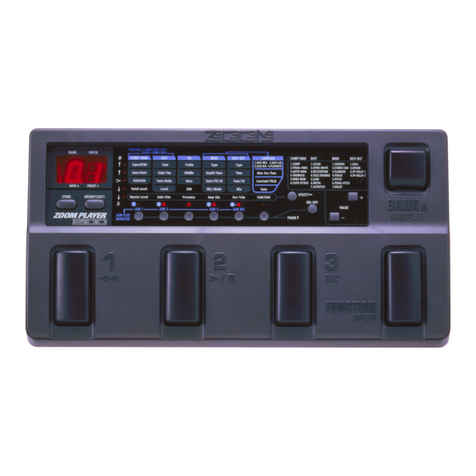
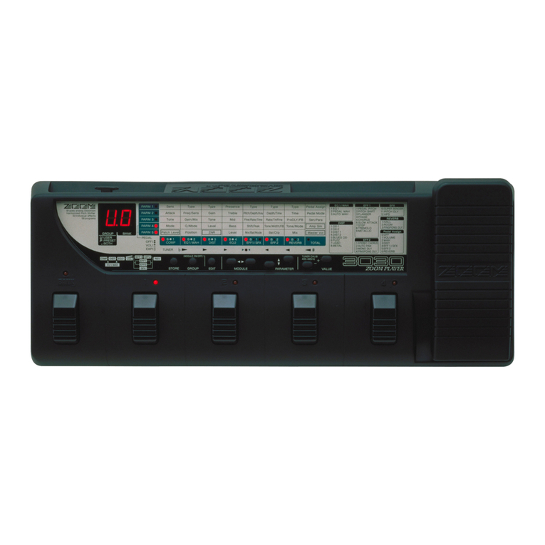
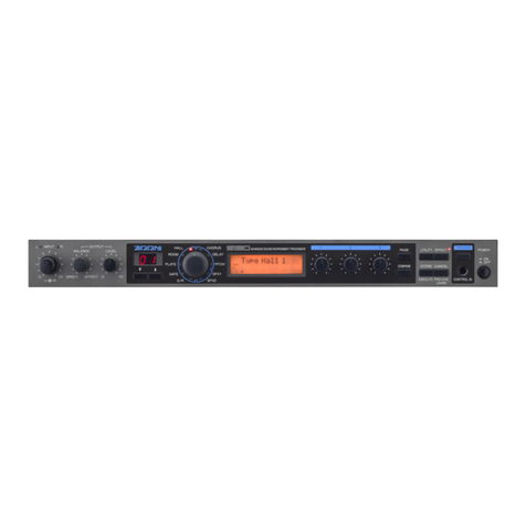
Zoom 9030 User manual

ADVANCED INSTRUMENT
EFFECTS PROCESSOR
High-Tech Tools for Artistic Expression

WARNING!
Danger of explosion at incorrect battery change.
Use same type
of
battery or of equivalent type recommended
by
manufacturer.
Always discard the battery acording
to
the manufacturer's instructions.
ADVARSEL!
Lithiumbatteri
-
Eksplosionsfare ved fejlagtig handtering.
Udskiftning
ma
kun ske
med
batteri af samme fabrikatogtype.
Lev6r det brugte batteri tilbage til leverandoren.

Congratulations and thank you for purchasing the
ZOOM
9030
Advanced Instrument
EffectsProcessor.
The
9030
is a sophisticatedmulti-effectdevice with the followingfeatures
and
func-
tions:
*
A
total of
47
basic individual effects, which are built into the 9030.
Up to seven of these effects can be combined in a multi-effect sys-
tem, enabling a wide range of signal processing applications, from
the reproduction
of
standard sounds to the creation of special syn-
thesizer-likeeffects.
A
logically-designed, intuitive user interface, which allows you to
operateand control it aseasily as you would a simple pedal effect.
*
Built-inanalog distortion effect with broad sound variation.
Simultaneous control over external effect devices, through the
provided sendreturn terminals.
Real-time effect parameter modulation, which allows you to
dynamically change effect parameters by using the optional 8050
foot controller andora MIDI keyboard.
Please take the time to read this manual carefully, in order to get the most out of
your
9030
and
ensure longtime use
and
reliability.

Safety
Precautions
Keep
in mind the following safety tips and precautions for
optimum safe use of the
9030.
Power Requirements
A
special
AC
adaptoris designed for use only with the 9030.
Make sure to
use
the
included
AC
adaptor
(AD0002).
Use
of another
AC
adaptor
can
cause
malfunctions
or
damage.
Make
sure
to
consult with your local
ZOOM
dealer about the
use of
a
proper AC adaptor or voltage converter when using
the
AC
adaptor in
an
area
(for example, another country)
where
~e
power supply voltageisdifferent.
Environment
Avoid using
your
9030 in environments where it will
be
exposed to:
Temperatureextremes
High humidity or moisture
Excessivedustor sand
Excessivevibration or sudden shock
Handling
Since the 9030 is a precision electronic device, avoid apply-
ing excessive force
to
the switches and buttons. Though the
9030
has been constructed for sturdiness and reliability,
dropping,smashing,or applying
too
much weight
to
the pro-
duct can causedamage,
Remodeling
Never open
the
case of the 9030 or attempt
to
modify the
productin
any
way
since
this
can result in damage.
Connecting
cables
and input and
output
jacks
You should always
turn
off the power before connecting
any
cables. Also make sure
to
disconnect all cables and the
AC
adaptorbefore moving the
9030.
Caution!
The
9030
contains a long-life lithium battery which
maintainsthe effect programs storedto the internal
memory even when the unit is turned
off.
With
normal use, the battery should last for approxi-
mately five years. To avoid possible data loss,
contact your local
ZOOM
dealer five years from
the date
of
purchase and have the battery
replaced
by
a qualifiedtechnician. Do not attempt
to replace the battery yourself, since installing an
improperbatterycould result
in
an explosion.

Precautions
4
Outline of the Manual
5
Section
I:
Introduction
6
Terms UsedInthe Manual
6
Names and Functionsof the Controls
and Terminals
7
Section
II:
Tutorial
10
Connections
Setup
UsingEffects
Editing Effects
Compare
Storingthe EditedPatch
Section
Ill:
Play Mode
Functionsof the Playmode
Settingthe 9030
to
the Play Mode
Display of the
Play
mode
SelectingPatches
Bypassing All Effects
Changing the Master Level
Storing Patchesfromthe Play Mode
Section IV: Edit Mode
Patch Structure
EffectModules
Effect
Types
Routing
Edit
Mode
What is
the
Edit Mode?
Enteringthe Edit Mode
SelectingEffect Modules
Display of the Edit Mode
ChangingParameter Values
SelectingPages
Turning
the Effect Module
Off
Real-timeModulation
Effect Typesand Parameters
Compare
Memory Areas and Buffers
Storing Inthe Edit mode
Section
V:
Utility Modeand Pop-upMenu
-
Utility Mode
Enteringthe Utility Mode
ExitingFrom
the
Utility Mode
SelectingDisplay Pages
Utility Mode Pages
Pop-up Menu
What
is
the Pop-up Menu?
1.
Memorizing Program ChangeNumbers
2.
Monitoring of the ControlChangeNumber
Self-introduction Function
SectionVI:
Example Applications
-
RemoteControland Real-time Modulation
Controllingthe9030 from the
8050
Equipment Connections
and
Settings
Selectinga Patch from the 8050
Bypassing All Effectsfrom the 8050
TurningOff Each EffectModule from the 8050
Real-timeModulation Using the 8050
Controllingthe9030with a Synthesizer
Connections
Equipment Settings
SelectingPatches of the 9030
from the Synthesizer
Real-timeModulation Using
the Modulation Wheel

Precautions
ElectricalInterference
The
9030
uses digital circuitry that may cause interference
and noise if placed
too
close to other electrical
equipment,
such
as
TV
sets and radios. If such problems
occur,
move
the
9030
further away from the dfected equipment. Also,
when fluorescentlightsordeviceswith built-in motors are
in
closeproximity to the
9030,
the
9030
may not function prop-
erly.
Cleaning
Use a soft,
dry
cloth
to
clean the
9030.
If
necessary,
a slight-
ly
damp
cloth can also
be
used. Do not
use
any
abrasive
cleansers, waxes, or solvents (such
as
paint thinner
or
alco-
hol), since
these
may dull the finish or damage the surface.
Keep this manual in
a
safe,convenientplace for future refer-
ence.

Outline
of
the
Manual
Section I: Introduction
This section explains the terms used throughout the manual
and the names and functionsof the panel conhnls and termi-
nals.
Section 11: Tutorial
This section is a "guided tour" of the 9030 that leads you
through the various functions and operations of the unit,
from making all the initial connections and setting up each
piece of equipment to storing your newly edited effect pro-
grams. Even if you have a lot of experience using multi-
effect devices, we recommend that you take some time to
look through this section.
Section Ill: Play Mode
This section explains in detail the operations of playing
selected effect programs of the 9030. If you wish to start
processing sounds
as
soon
as
possible, read this section after
the
Tutorial section.
Section IV: Edit Mode
This section explains the operations of the Edit mode,
in
which the Patches of the 9030 are edited. The parameters of
the basic effect programs are also explained in this section.
If
you wish to start editing your own effectprograms, read
this sectionafter the Tutorial section.
Section
V:
UtilityMode
and
Pop-up Menu
This section explainsthe remaining miscellaneous operations
of the 9030, such
as
naming of the effect programs, MIDI
operations
in
the Utility Mode, and the convenient pop-up
menu.
Section VI: Example Applications
--
RemoteControl
and
Real-timeModulation
This section explains how to control the 9030 remotely by
using the optional 8050 foot controller and MIDI devices
such
as
a
synthesizer.
If
you areusing the 9030 with a
MIDI
keyboard (or other MIDI device), you should read this sec-
tion to get the most out ofyour equipment.

This
section explains some of the terms used throughout the
manual,
as
well
as
the names and functions of the panel con-
trols and terminals.
Terms
Used
in
the
Manual
Effect
Module
The 9030 consists of basic effect blocks, which are listed
below. Each block is referred
to
as an "effect module." The
followingare the types of effectmodules:
COMP (Compressorgroup)
EXT
(Externaleffect)
DIST (Distortiongroup)
EQ
(Equalizer
group)
AMP
(Amp simulation group)
EFF
1(Miscellaneous effects 1)
EFF
2 (Miscellaneouseffects 2)
SFX (Special effects)
REV
(Reverb
&
echo group)
Effect Types
Each effect module
has
several different effect programs,
which are referred
to
as effect types.
See
page 19 for infor-
mation on the kinds of effect types. One effect
type
can be
selected foreach effect module.
Patch
The9030allows you to use a maximum of seven effect
mod-
ules simultaneously.
A
group of effect modules, each with
their own effect type settings, is referred
to
as
a Patch. The
9030 can store up to 99 Patches in the internal memory
(Patch numbers
1
-
99).
Parameter
The elements which determine the sound of an effect are
referred to as parameters. Parameter values
can
be
set for
each effectmodule for making Patcheson the 9030.
Page
Each screen of the display is referred to
as
a "page." When
the parameter is too large
to
be
displayed on a singlescreen,
its settingsaredivided over several displaypages.
Mode
The functions of the 9030 can be roughly divided into
three
different categories or types. These types are referred
to
as
"modes"and
are
describedbelow.
Play Mode
--
In this mode, Patches can
be
selected and
played. When the power is turned on, the
9030
is automati-
cally set to this mode.
Edit Mode
--
In
this mode, the parameters of each Patch
can
be
edited.
Utility Mode
--
This mode is
used
for naming Patches and
settingthe MIDI channel.
Block
Diagram
Patch
-
-
OUTPUT
DlST
-
EXT
.
1
/
AMP
-
Effect
module
SFX
EQ
-
REV
-
EFF1
-
-
EFF2

Names and Functions of
the
Controls
and Terminals
Front
Panel
(1)
lnput gain volume
For adjusting the level of the input signal. This control
affects both the
Hi-Z
INPUT
terminal on the front panel and
the
INPUT
terminal
on
the rear panel.
(2)
lnput level indicator
For monitoring the level of the input signal. When an input
signal is received, the
LED
at the bottom lights up in green
and changes in color to amber
as
the level becomes greater.
When a high level signal capable of causing distortion is
input,the
LED
at the top lights up in red.
(3)
Hi-Z INPUT
(high
impedanceinput)terminal
For connection of instruments such as electric
guitar
and
bass. This terminal cannot
be
used simultaneously with the
INPUT
terminal on the rear panel. When both terminals are
connected,the
Hi-Z
INPUT
terminal has priority.
(4)
PHONES(headphone)terminal
For connection of a setof stereo headphones.
(5)
Headphonevolume
For adjustingthe level output through the stereoheadphones.
(6)
PATCH
NO.
(Patchnumber) indicator
Indicatesthe Patch number
(1
-
99) of the selectedPatch.
When storingan
edited
Patch, the destination Patch number
is indicated.
(7)
PATCH
V
key, PATCH
A
(COMPARE) key
In
the Play mode, this key is used to select Patches. The
Patch number increasesby one each time the PATCH
A
key
is pressed, and decreases by one upon each press of the
PATCH
V
key.
In the Edit mode, PATCH
A
key is used in monitoring
to
compare the Patch currently being edited with the original
Patch (thePatch as it was beforeediting).
(8)
Display
Shows various information necessary in operating the 9030,
such
as
Patch names, effect parameter values and other mes-
sages.
(9)
Effect indicator
Displays the condition of each effectmodule.
In
the
Play mode, the indicators for effect modules that
are
currently
ON
light up in
red.
The indicators for those mod-
ules that are
OFF
light up in green.
In the Edit mode, the indicator for the module which is cur-
rently being
edited
flashes.
The indicators for the modules which are
ON
light up in
amber when all the effects of the 9030 are bypassed (tem-
porarily cancelled) from the Play mode and the Utility mode.
Front Panel
INPUT
6
PHONE
I
I
II
I
1
7-
I
T
I

(1
0)
STOREfEXECUTE key (16) Data EntryControls 1
-
4
In the Play mode
and
the Edit mode, this key is used to These controls are used
to
change parameter values. Up
to
open the Storemenu. four parameters can
be
set
simultaneously, providing opera-
tion
ease
and conveniencesimilarto that of a
pedal
effect.
In the
Utility
mode, this key is used
to
executeoperations.
(17) Power switch
(11) EXITkey
For turning the power to the
9030
on
and
off.
This key is
used
to
leave the Edit
mode
or Utility mode
and
return to the Play mode.
(1
2)
UTILITYIPAGEkey
In
the
Play mode, this key
is
used
to
enter theUtility mode.
In the Edit mode, this key is used as
a
"page" key forcall-
ing up
each
"page" included
in
the
Edit mode.
In the Utility mode, this key
is
used
as
a page
key
for call-
ing
up
the pages included in the Utility mode.
(13) PRGCHG
LEARN
key
(also
EC
V
key:
decrement)
l
CTL-CHG
MONrrOR
key
(am
INC
A
key:
increment)
In the Play mode, this key is used to call up the pop-up
menu.
(See
page
50
for information on the
popup
key.)
In
the
Edit
mode, this key is used mainly for selecting
the
effect
type.
In theUtility mode, this key is
used
to
inputdata.
(14) BYPASSkey
In the Play mode or Utility mode, this key is used
to
turn
all
the effect
modules
on
and
off. (Only the direct sound is out-
put when the modules areoff.)
In the Edit mode, this key
is
used to
turn
each effect mod-
ule
ON/OFF.
(15) EDIT
<
l
>
keys
In the Play mode, thiskey is used
to
enter the Edit mode.
In the Edit mode, this key is
used
@
select the effect mod-
ule for editing.
In the Utility mode, this key is used
as
a
cursor position
control for moving the cursor
in
the display to the left and
right.

Rear
Panel
(1
)
AC
adaptor terminal
For connection of the included
AD0002
AC adaptor.
(2)
REMOTE INtermlnal
For connection with a controller equipped with a
ZOOM
remote out terminal, such
as
the optional 8050 Advanced
Foot Controller.
(3)
MlDIterminals
For connection to other
MlDI
devices, such
as
a synthesizer
or to a computer
(via
MIDI
interface). These are used for
remotely controllingthe 9030 from a synthesizer, or for stor-
ing
data
of the 9030to a computer.
(4)
OUTPUTterminals
For connection
to
an
amplifier/speaker system, mixer, etc.
The method of outputchanges depending on the output mode
(
Seepage
44
)selected.
(5)
EXTERNALSENDlRETURNterminal
For connection of an external effect device. The 9030
can
memorize the settingof the signal level sent to the connected
externaleffect,
as
well
as
the ONIOFF status ofthe effect.
(6)
INPUTterminal
For connection of musical instruments with relatively low
output impedance,such
as
a synthesizer or rhythm machine.
This terminal cannot
be
used simultaneously with the Hi-Z
INPUT
terminal on the frontpanel. When
both
terminalsare
connected,the Hi-Z
INPUT
terminal has priority.
Rear
Panel
r
OUTPUT1
r
EXTERNAL
-I
R
L
RETURN
SEND
I
lNpLn
I
/I

This section provides a guided tour of the 9030 that takes
you step-by-stepthrough the various functions and opera-
tions of the unit. We recommend that you
read
through this
section while actually operating the 9030 in order
to
better
understand the structure of 9030 and to get accustomed
to
the
various operations.
Connections
1.
Connect the
AC
adaptor.
Connectthe
AC
adaptor
to
the 9030,and plug it into the out-
let.
Do
NOT
turn
on the power yet.
2.
Connect the musical instrument and the amplifier1
speaker system to the
9030.
Connect the outputof the musical instrument to the input ter-
minal of the 9030. Connect a guitar or bass to the Hi-Z
INPUT
terminal on the frontpanel, and musical instruments
such as a keyboard or rhythm machine, whose output
impedance is comparatively low,
to
the
INPUT
terminal on
the
rear
panel.
Connectkm Examples
1
-
3
Connection
wlth
guitar
and bass
Connectionwith keyboardandtone generator
INPUT
Keyboard
9030
MixerIAmplifier
Connection
wlth
PA
and recordingsystem
9030
Mixer
Now connectthe OUTPUTterminal of the 9030
to
the arnplifi-
cation system or mixer. When using a mono signal, connect it
to
the
WON0
terminal; when using stereo signals, connect
both outputsof the 9030
to
the amplification system.
3.
Turn on the power of the devices
in
the following
order:
1)
The musical instrumentswhich areconnected
to
the 9030,
such
as
a keyboard or sound
source
module.
2)
The 9030.
3) The amplifier/speakeror mixer system,
This order is important
to
prevent speaker damage. Turn off
the power in the reverse order.
Setup
After completing all of the connections, you will have
to
match the level settings of the 9030
to
those of the musical
instrument and the amplification system. This may seem
to
be
a
bit involved and troublesome. However, once it's
accomplished,you should never have to make these settings
again,
as
long
as
you keep the currentconnectionsintact.
l.
Adjust the input gain level while playingthe connected
musical
instrument.
Begin the setup operation by setting the levels of the con-
nected equipment. Set the
musical
instrument
to
the level at
which you normally play, then adjust the input gain level of
the 9030 so that the red
LED
on the 9030 occasionally lights
up when the volume is at the maximum.

2.
Press the
UTILITYIPAGE
key.
Set the 9030 to match the characteristics and the playback
method of the amplification or mixer system. Enter the
Utility Mode of the
9030
by pressing the UTILITY/PAGE
key. Thedisplay shown below will appear.
Note:
You may have to press the
UTILITYPAGE
key several
times if the top line of the display differs from the
FL
display
shown below. The information indicated in the bottom line
of the display differsdepending on the setting.
UTILITY
W
The parameter currently shown at the cursor position is
the
function used
to
change the characteristics of the 9030 to
match those of the playback system. The 9030is designed to
provide consistently high sound quality whether played
through a conventionalaudio system or a guitaramplifier.
Select
LINE
when using a conventional audio system or
when recording directly to
a
tape
recorder, and select
AMP
when using a guitar amplifier.
4.
Move the cursor to the right parameter by pressing
the EDIT
>
key.
UTY1 OUTPUT MODE
1
LINE STEREO UTYI OUTPUT
MODE
1
AMP STEREO
From
this
dqlay,you can set the characteristicsand playback
method of the 9030. The mark
"
)
"
in the display is called the
cursor, and only the parameter indicated by this cursor can be
set. Try pressing the
EDIT
<
/
>
keys now. The cursor should
movebetween the parameters on the left and right,
The parameter on the right determinesthe type of output for
the 9030. Select
"STEREO"
when using stereo outputs, and
select
"MONO"
when outputting
a
mono signal. Set it
accordingly for the playback system you
use.
5.
Press the
EXIT
key after completing the settings.
3.
Change the settings by using the DEC
VhNC
A
keys.
With the cursor in front of the left parameter, press the
INC
A
key, then the
DEC
V
key.
"LINE"
and
"AMP"
will alter-
nately appearat the left
in
the display.
UTYl OUTPUT MODE
I
)
LINE
STEREO
CTL-CHG
MONITOR
(INC
A
key)
UTYl OUTPUT MODE
STEREO
Doing this exits from the Utility mode and enters the Play
mode, for selectionof Patches.
Note:
The
FL
display below shows one example display from
the
Play mode. The actual display will differ depending on the
settingsmade and the Patch which was last selected.
ADVANCED PITCH2
LI
NI
ST LVL
100
6.
Adjust the level of the playback system.
Set the volume of the playback system to an appropriate lev-
el while playing the c0~ect.dinstrument. This completes
the setuppreparation.

Using
Effects
Now that you can finally hear the sound,
try
out the various
effects
of
the
9030.
Selecting Patches
1.
Check that all the devices are connected correctly and
the power
is
turned on.
2.
Set the
9030
to the Play mode.
When 9030
is
in anothermode, press the
EXIT
key repeated-
ly until thePlay mode display appears.
Helpful
Hint:
If you have "wandered" into some unfamiliar 9030
operation,pressing the
EXIT
key repeatedly is an easy and
convenient way
to
return you to the familiar territory of the
Play mode.
In the
Play
mode, the currently selected Patch number
(1
-
99) is shown by the
PATCH
NO.
indicator and the following
informationis
also
displayed:
ADVANCED
PITCH2
LI
NIST
LVL
100
(1)
Patch name
(2)
Output mode (The playback method you selected in the
setupoperationabove is indicated here.)
(3) Master level (This is the master volume of the direct
sound
and
the effect sound. It can
be
set independently for
each Patch.)
3.
Select the Patch by using the PATCH
VIA
keys.
Press the PATCH
V/A
keys while playing the connected
musical instrument. Notice that the effect sounds are
changed one afteranother.
Selectthe next highest Patch number by pressing the
PATCH
A
key once, and select the next lowest Patch number
by
pressing the
PATCH
V
key.
Helpful
Hint:
It is possible to switch the Patches with your foot if you use
the 8050.
See
page
52
for more information.
Bypassing Effects
The 9030 has a function that allows you
to
bypass,
or tem-
porarily cancel,all effectswhileplaying.
l.
Makesurethat the
9030
is in the
Play
mode.
2.
Bypass
the current effect
by
usingthe BYPASS key.
Press
the
BYPASS
key while in the
Play
mode.
The
"BYP"
indication at the bottom right of the
display
flashes,
and
only
the direct(or
"dry")
instrumentsound is output from the 9030.
BY
PASS
PI
I
ADVANCED
PITw21
1
LI
N
/
ST
LVL
l
OO,J3YP
3.
The bypass function is released when the BYPASS key
is
pressed again, and operation returns to the previous
condition.
Helpful
Hint:
The
bypass function
is
especially convenientwhen tuning a
guitar or bass, or checking how much effect is being applied
to the sound.
Adjusting the
Master Volume
1.
Change the master volume
by
using Data Entry
Control
1.
Data Entry Control
1
at the right sideof the display functions
as
a
master volume control
in
the Play mode.
Try
rotating Data
Entry
Control
1
to
the left then the right
while playing the connected instrument. The value of the
"LVL
parameter in the display changes and the level of the
direct sound or effect sound changes.
(The
letter
"
H
"
which
means "Edited appears in the
FL
display.)

ADVANCED
PITCH2
1
LINiST
LVL
100
ADVANCED
PITCH2
l3
LI
N
1
ST
LVL
80
Helpful Hint:
The master volume setting made here can
be
set indepen-
dently and stored for each Patch as part of the
data
included
in
the Patch.
See
page
15
for more on storing operations.
Editing
Effects
The Patches in the user memory of the
9030
can be edited
and stored
to
any Patch number.
1.
Selectthe Patch to be edited in the Play mode.
2.
Enter the Edit mode by pressing the
EDIT
c
/
>
keys.
The Patches of the
9030
consist of nine different types of
effect modules, including a compressor group and a distor-
tion group. (Up
to
seven effect modules can
be
used at the
same
time.) In the edit mode, each effect module
is
called up
to the display individuallyand the parameters of the module
can
be
set.
For example, when you enter the Edit mode from the Play
mode by pressing the EDIT
c
key, the display shown below
appears. This display is for editing the REV (reverb) effect
module. The effect indicator "REV"lights up in
red,
indicat-
ing that the reverb module parameters
can
currently be
edited.
TYP
RvT
PDI
COL
MIX
Rv2 2.4
60
5
40
Note:
The
FL
display shown above is only an example. The actual
values will differ depending on the Patch selected in the Play
mode.
If you enter the Edit mode from the Play mode by pressing
the EDIT
>
key, the
FL
display will show the
COMP
(com-
pressor group) effect module for editing. In either
case,
pressing the EDIT
<
key or EDIT
>
key several times toward
the same directionreturns operation
to
the Play mode.
HelpfulHint:
It may
be
easy
to
think of the operation
as
circulatingaround
the Play mode (as shown
in
the chart below) when selecting
effectmodules with the EDIT
c
/
>
keys.
3.
Change parameter values by rotating the appropriate
Data Entry Control.
Data Entry Controls
1
-
4
are used in order to change the val-
ues in the Edit mode.
Try
rotating Data Entry Control
4
to
the left then
to
the right. Thevalue at the bottom right of the
display
((5)
in the
FL
display chart on the next page) changes
and the sound will
also
change. (In this example,the level of
the reverb changes.)
Circulationof theeffect modules and the play mode
Edit
mode
i
r
1
I
Play
mode
I
I

UTILITY
TYP
RvT
PDI
COL
MIX
Rv2
2.4 60
5
40
ttt
tt
(1)
(2)
(3)
(4)
(5)
TYP
RvT
PDI
COL
MIX
ORv2
2.4
60
5
50
The letter
"
H"
is displayed at the left of the display when the
value is changed. The
"1"
mark indicates that the parameter
in thePatch hasbeen changed.
Try
rotating the other
Data
Entry Controls(1
-
3) in the same
way. The parameter values of
(2),
(3)
and (4) in the above
illustration will change.
Note:
Parameter (1) in the chart above will not change even though
the corresponding Data
Entry
Control is rotated. This is a
special parameter which is used
to
select the effect type, and
it
can
be
used only when changing the
type
of effect (for
example, from reverb
to
multi-tap delay) by using the DEC
'I/INC
A
keys.
When
the
effect type is changed, other parameters are also
changed (for example, from the reverb parameters to the
multi-tapdelay parameters). Refer
to
Section
IV
fordetails.
4. Call
up
other pages
by
using the UTILITY/PAGE key.
t
y
p
DES
CTL
(%)
SRC
ORv2
RvT
1
-100
2
Note that new parameters are displayed in positions
(2),
(3)
and
(4).
The parameter values of
(2)
through
(5)
can
be
edit-
ed by using Data Entry Controls
1
-
4 on
this
page,
as
well.
HelpfulHint:
When editing the parametersof the effect module, remember
that the parameters are divided over two or three display
pages.
5.
Return to the first page by pressing the
UTILITYIPAGEkey.
The display returns to the first page by pressing the
UTILITY/PAGE key again. (Press the key twice when the
parameters are divided over three pages.)
6.
Call up other modules by using the EDIT /
>
keys
and edit the parameters as describedabove.
HelpfulHint:
Remember that the Edit mode consists of
the
followingbasic
operations:
Selectingthe effect module (with
EDIT
c
/
>
keys)
Selectingthe effect type (with DEC VIMC
A
keys)
Selectingthe page (with UTILITYIPAGE key)
Changingthe parameters (with
Data
Entry Controls
1
-
4)
Press the
UTILITY/PAGE
key.
This
callsup anotherpage of
the
REV
effezt module parameters.

Compare
key is pressed.
STORE
While you
are
editing the parameters, you can temporarily
hear the original sound of
the
Patch, before it was changed,
and compareit with the sound
of
the newly edited one.
The
compare function allows you to do this.
1.
Press the PATCH
A
key after changing the parame-
ters in the Edit
mode.
88
ADVANCED PITCH2
H+
ADVANCED PITCH2
The display changes
as
shown below and
the
all the parame-
ters of the Patch revert
to
the original settings. Press the
STORE/EXECUTE
key
to
memorize the Patch
to
the same same Patch number in the memory. The edited
Patch is then stored
to
the same Patch number and operation
returns to the Play mode.
HelpfulHint:
You can alsochange the name of aPatch when you store it to
memory. Seepage
45
for more information.
ADVANCED PITCH2
COMPARE
2.
Press one of the EDIT /
>
keysonce.
2.
Selectthe destination Patch number by
using
the
PATCH
VIA
keys.
Assign the Patch number by using the PATCH
V/A
keys
when storing the edited Patch
to
a
different Patch number.
(You
can
confirm the number from thePATCH
NO.
indicator.)
This returns operation to the Edit mode. The EXIT key or
UTILITY/PAGE key
can
also
be
used instead of the EDIT
c
/
>
keys.
HelpfulHint:
The comparefunction is convenient for checking how much
the entiresound is
affected
by editing a singleparameter.
Storing
the
Edited Patch
Finishingup this Tutorial section isan explanation on storing
a Patch to memory. Any editing you have done to the
parameters so
far
is temporaryand it will
be
irretrievably lost
if
you switch to editing anotherPatch before storing the cur-
rent one to memory. To avoid this, make the following
a
habit:
once
you'vecreated
a
Patch you like,
IMMEDIATELY
storeit to memory.
1.
Press the STORE/EXECUTEkey in the
Edit
mode.
P-
P
88
ADVANCED PITCH2
H+
TubeAmp
Sound
The destinationPatch name
is
indicated in the bottom line
of
the display. The edited Patch is stored to the new Patch
number and operation returns to the Play mode when you
press the STORE/EXECUTE key. The store operation can
be
cancelled by pressing the EXITkey.
Note:
When the Patch is stored, the Patch which was previously
stored to the destination memory space is automatically
erased. Make absolutely sure that the Patch at the destina-
tion can be erased.
This completes the
Tutorial
section.
We
trust this
has
been
helpful
as
an introduction
to
the
basic operations of the
9030.
Plcasego on to read the rest of the manual
to
get toknow the
9030
better and learn more of its sophisticatedand advanced
functions.

The functions of the Play mode are fully explained
in
this
section.
(1)
Patch name
(2)
Output mode
(3)
Master level (volume)
Functions
of
the Play
mode
The Play mode is the basic mode of the 9030 in which
Patches
are
selected and played. The following operations
can
be
donein the Play mode:
SelectingPatches
Bypassingall effects
Manually changingthe master volume
Setting the
9030
to the Play Mode
When 9030is in another mode, press the EXIT key repeated-
ly until the Play mode
is
selected. You can also turn the
power off and back on
again;
when the power is turned on,
the 9030
is
automatically set to the Play mode.
Effect indicator
--
Erfect modules which
are
currently on
in
the selectedPatch light up in
red.
Modules which
are
off
in
the Patch light up
in
green.
Selecting Patches
Use the PATCH
VIA
keys
to
selecta Patch.
Press the PATCH
A
key once
to
selectthe next highest Patch
number, and press the PATCH
V
key
to
select the next low-
est Patch number. The values
"wrap
around"; if Patch num-
ber
99
is currently selected and you press the PATCH
A
key,
Patch number
1
will be selected. Similarly,if Patch number
1
is selected
and
you press the PATCH
V
key, Patch number
99
will
be
selected.
Display
of
the Play mode
The followinginformation is displayed on the panel fiom the
Play mode.
PATCH NO. indicator
--
This indicates the selected Patch
number
(1
-
99).
Display
--
The following information is shown in the
FL
display:
Patch number Effect module
ON
Patchname indication (red)
Hi-Z
S~ML
INPUT
PHONES
DSP
I
ADVANCED
PITCH2
I
j[_
I
LIN/ST LVL
100
mEq
i
1
BYPAS
1
E]
COMPARE
EXECUTE
0
0
PAGE
00-
A
Output mode Master level Effectmodule
OFF
indication(green)

Bypassing
All
Effects
Alleffectscahb~~assdb~~ressingtheBYPASSke~in
StoringPatchesfromthePlayMode
the Play mode. The
"BYP"
indication in the display will
flash.
In
the effect indicators, the indicator'of the effect
U,
this
store
operation
when
you
wish
save
the
master
being
used
changes
From
red
to
which
indicates
that
level setting of a Patch or copy a Patch to a different
Patch
the effect
has
been temporarilyturned off. number.
LIN/ST
LVL
100
ADVANCED PlTw21
,!P
play changesas shown below.
Press the STORE/EXECUTE key after changing the master
level in order
to
store the newly edited master level.
The
dis-
Note:
You cannot enter
the
Edit mode while using
the
bypass func-
tion.
88
ADVANCED PITCH2
H+
ADVANCED PITCH2
The
function
is
by
pressing the Pressing the STORE/E=CUTE key stores the Patch whose
again. master level has
been
changed to the same Patch number.
Cancel the storeoperation by pressing the
EXIT
key.
Changing
the Master Level
The master level of a Patch (master of the direct To storethe Patch to a differentPatch number, first press the
sound and effect sound)
cm
be
changed in the Play mode
by
STORE/EXECUTE key then select the destination Patch
using Data Entry Control
1.
number with the PATCH
VIA
keys. (You can confirm the
The master level value in the display is changed by rotating number
from
the
PATCH
NO.
indicator.)
Data Entry Control
1,
changing the entire volume of the
9030.
Helpful
Hint:
The master volume setting made here
can
be
set indepen-
dently
and
stored for each Patch as
part
of the parameter
data
8
8
ADVANCED PITCH2
I-+
TubeAmp
Sound
of the Patch. Refer
to
the following explanation on storing
The
Patch
name
is
indicated
next
to
the
selected
Patch
num-
Patches. ber in the bottom line of the display. Pressing the
STORE/EXECUTE key again stores the Patch
to
the new
Patch number. Pressing theEXIT key cancels the store oper-
ation.
Note:
When a Patch is stored, the Patch which was previously
stored at the destination Patch number is automatically
erased. Make absolutely sure that
the
Patch at the destina-
tion can
be
erased.

This section explains the Patch programming operations of
the
Edit
mode.
Patch
Structure
In order for you to best understand how to program the
effects
of
the
9030,
you should first have a
firm
grasp of the
structure of a Patch. The explanations that follow describe
the different kinds of effect modules and effect types of the
9030
and how
the
signalsareprocessed.
Effect
Modules
The
9030
consists of the following effect modules:
COMP
(Compressorgroup)
EXT
(Externaleffect)
DTST
(Distortiongroup)
EQ
(Equalizergroup)
AMP
(Amp simulator group)
EFF
1
(Miscellaneouseffects l)
EFF
2 (Miscellaneouseffects2)
SFX
(Special effects)
REV
(Reverb
&
echo group)
HelpfulHlnt:
The master level (set
in
the Play mode
)
and Patch name (set
in the Utility mode)
are
added
to
the settings of the effect
module,
and
all
are storedto memory
as
a
Patch.
The
SFX
and
EFF
1/2 modules above cannot
be
used simul-
taneously. For example, when the
SFX
module is selected,
EFF
1/2 modules are automatically turned off. Likewise,
selectionof either
EFFl
or
EFF2
cancelsthe
SFX
module.
Effect
Types
The
following chart shows
the
effect
type
installed
to
each
effect module. Effects marked
with
an
asterisk
(*)
are
stereo
effects.
Structure
of
Effect
Modules
EXTERNAL
SENDJRETURN
T
SFX
L
DlST
P
INPUT-
REV
-
-
EQ
-
1
-
OUTPUT
R,
EFF2
COMP
-
EXT
-
Table of contents
Other Zoom Computer Hardware manuals
Popular Computer Hardware manuals by other brands

Velleman
Velleman K8042 Illustrated assembly manual

Resolution Products
Resolution Products RE926S-03-00 OWNER'S OPERATION AND INSTALLATION MANUAL

IEI Technology
IEI Technology PCIE-H610 user manual

Matrox
Matrox RT.X2 user guide

Pilz
Pilz PNOZ mc5p operating instructions

Panasonic
Panasonic MICROCOMPUTER MN103S user manual