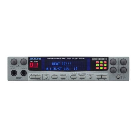
Zoom 9120 User manual

ADVANCED SOUND
ENVIRONMENT PROCESSOR
OPERATION MANUAL

There is a danger of explosion if the battery
is
not replaced properly. Use
only
the same type of battery or an
equivalent type as recommended
by
the manufacturer. Always dispose
of
the battery according to the
manufacturer's instructions.

Congratulations
and
thank
you forpurchasing
the
ZOOM 9120
Advanced Sound Environment Processor.
The
9120
is a
sophisticated effectdevice with
the
followingfeatures
and
functions:
*
A
total of
22
basic effects. They include the reverb effects of Hall, Room, Plate (each with two
distinct types), as well as Gate and Early Reflection. Also available are Chorus, Delay and
Pitch Shift, plus six other special effects (included in the SFX
1
and
2
settings).
*
Exceptional high-quality sound, for professional studio recording applications. The reverb
sound, in particular, rivals the sound of professional units costing many times more, and stands
up well to the exacting sonic demandsof digital recording.
*
Extremely intuitive and easy operation. The effectselector dial allows you to instantly choose
the basic effect you want, while three dedicated Data Entry controls let you instantly edit up to
three parameters of the effect at a time. While all efl'ects areof high quality and sophistication,
the number of different parameters has been kept to a minimum for greater ease in editing.
*
Unique and versatile special effects. The
9120
also provides a wide variety of special functions
and effects, including trigger control over the delay and gate reverb, built-in delay time
calculator, "karaoke" effect for filtering out the vocal signal in a music mix, surround
simulation, pedal-controlled pitch bend, MIDI-controlled pitch shift, and others.
*
Extensive
MIDI
functions. With MIDI, you can switch effect programs and make real-time
changes in the effect parameters from another MIDI device, such as a keyboard or sequencer.
You can alsostore your original effectprograms to a connected MIDI data storage device(or to
another
9120).
Please
take
the
time to read this manual carefully,
in
order to
get
the
most out of your
9120
and
ensure
longtime use
and
reliability.

Safety
Precautions Other Precautions
Keep in mind the following safety tips and precautions for
optimum safe use of the 9120.
Power
Requimments
A special
AC
adapter is designed for use only with the
9120. Make sure to use the included AC adapter
(AD-
0002). Use of another AC adapter can cause malfunctions
or damage.
Make
sure
to consult
with
your local
ZOOM
dealer about
the use of a proper AC adapter or voltage converter when
using the
AC
adapter in an area (for example, another
country)having a differentpower supply voltage.
Avoid using your 9120 in environments where
it
will
be
exposed
to:
*
Temperature extremes
*
High humidity or moisture
*
Excessive dust or sand
*
Excessive vibration or sudden shock
Handling
Since the 9120 is a precision electronic device, avoid
applying excessive force to the switches and keys. Though
the 9120 has been constructed for sturdiness and reliability,
dropping, smashing, or applying
too
much weight to the
product can cause damage.
Remodeling
Never open the case of the 9120 or attempt to modify the
product in any way, since this can result in damage.
Connecting
Cables
and lnput and Output
Jacks
You should always turn off the power before connecting
any
cables.
Also
make sure to disconnect all cablesand the
AC adapterbefore moving the 9120.
Electn'cal Interference
The 9120 uses digital circuitry that may cause interference
and noise
if
placed too close to other electrical equipment,
such
as
TV
sets and radios.
If
such problems
occur,
move
the 9120 further away from the
affected
equipment. Also,
use of fluorescentlights or devices with built-in motors in
close proximity to the 9120 may result in malfunctions
and/ordegradedperformancein the 9120.
Cleaning
Use a soft, dry cloth to clean the 9120. If necessary, a
slightly damp cloth can also be used. Do not use any
abrasivecleansers,waxes, or solvents (such as paint thinner
or alcohol), since these may dull the finish or damage the
surface.
Malfunctions
If your 9120 does not perform
as
expected, or malfunctions
occur, first make sure all related,volume controls are at
their minimum to avoid damaging any other equipment,
then disconnect the power and other cables connected
to
the 9120. Contact the shop from which you purchased the
9120 and provide them with the following information:
model name, serial number, description of the problem,
your name, address and telephone number.
Keep this manual in a safe, convenient place for future
reference.
Caution!
The
9120
contains a long-life lithium battery which maintains the effect programs stored to the internal memory
even when the unit is turned off. With normal use, the battery should last for approximately five years.
To
avoid possible data loss, contact your local
ZOOM
dealer five years from the date of purchase and have the
battery replaced by a qualified technician.
Do
not attempt to replace the battery yourself, since installing an
improper battery could result
in
an
explosion.

Table
of
Contents
Introduction and Main Features
Safety Precautions
SectionI: Names and Functions of the Controls and Terminals
Section11: Setting Up and Using the
9120
Making Connectionsand Setting
Up
the 9120
Using the Effect Programs
BypassingEffects
Editing
an
EffectProgram
Compare
S
toring an Edited Program
Section
In:
Effects andTheir Parameters
An
Introductionto Reverberation
Effects and
Their
Parameters
Hall
Room
Plate
Gate
E/R
(Early
Reflection)
Chorus
Delay Delay Time CalculatorUtility
Pitch
SFX
1
Karaoke
Surround
Sweep
Flanger
SFX
2
Pedal Pitch Shift
MIDI
HarmonizedPitch Shift
User
Scale
Utility
Hold Delay
Section IV: Utility Mode and Program Change Learn
Utility Mode
Program
ChangeLearn
Specifications
MIDI Implementation
MIDI Implementation Chart

Front
Panel
(1
)
INPUT dial
(2)
Input
levelindicators
rl
L0
INPUT
0
R
7
OUTPUT1
BALANCE LEVEL
L*>R
(3)
OUTPUT
BALANCE
dial
(4)
OUTPUT
LEVEL
dial
(5)
Program number indicator
(6)
P
rogramr
1
A
keys
lnput/Output Controls
INPUT dial
For adjusting the level of the input signal. The inside
dial is for adjusting the left
(L)
channel and the outside
is for the right
(R)
channel. (When adjusting
separately, hold one dial in place while turning the
other.)
Input level indicators
For monitoring the level of the input signal. When an
input signalis received, the LED lights up in green and
changesin color
to
amber
as
the level becomes greater.
When a high level signal capable of causing distortion
is input, the LED at the top lights up in red. (For best
results,adjust the input level so that the
LED
is usually
in amber.)
OUTPUT
BALANCEdial
For adjusting the overall balance of the sound between
direct and effect. At the DIRECT position, the input
sound is heard without processing. At the
EFFECT
position, only the processed sound is heard. This
settingis applied globally to all effects.
OUTPUT LEVEL dial
For adjusting the overall output level.
Program/Effect Selection Controls
(5)
Program number indicator
Indicates the selected program number
(1
-
99).
(6)
Program
V
/
A
keys
For selectingprograms.
(7)
Effect
selector dial
(8)
LCD
display
LCD Display and Editing Controls
LCD
display
Shows various operating information, such as the
parameter values (up to three digits) and other
messages.
Data Entry controls
1,2
and
3
For adjustingparameter values.
Page key
For advancing through the different display "pages" in
the LCD. (The selected page and number of pages
available is indicated at the bottom left of the LCD.)
Compare key
Used in editing a program, this switches back and forth
between the currently edited values and the values of
the original program, allowing comparison of the
sound. When in the Utility mode, this key is used to
select the previous displaypage.
UTILITY
key
For selecting the functions of the Utility mode (such
as
settingthe MIDI channel, transferring
data,
etc.).
EFFECT key
For canceling the effect processing. The LED above
the key lights when the effect is on.
STORE(EXECUTE) key
For storing a program to internal memory. Press the
key twice to store the program to
the
selected program
number. When the LCD prompts you
to
confirm
an
operation with an
"OK?"
message, this key functions
as an EXECUTE key to actually perform the operation.
(7)
Effect
selector dial
For selecting effects. The
LED
indicates the currently
selectedeffect.
4
Section
I
:
Namesand Functions of the Controlsand Terminals

(10) Page key
r
(1
2)
UTILITYkey
(1
3)
EFFECTkey
COMPARE
I
(16)TRIGGER key
I
C
EXECUTE
PRG-CHG
CONTROL IN
I
I
l
I
(14) STORE (EXECUTE)key
1
(1
5)
CANCEL (PRG-CHGLEARN)key
L
(1
8)
Power switch
(9)
Data
Entry
controls 1,
2
and
3
(1
1) Compare key
I
(15)
CANCEL
(PRG-CHG
LEARN)
key
External Control
1
(17)
CONTROL IN jack
When in the Utility mode or Store function, this key is
(16) TRIGGER
key
used to cancel the operation and return to normal
operation. When
in
normal operation, it
is
used
to
call For tap-triggercontrol over certain effect parameters.
up
the Program Change
Le&
menu.
(17)
CONTROL IN
jack
For connectionof an external footswitch or foot pedal.
(You should use the optional
ZOOM
footswitch and
foot pedal for this.
)
(18)
Power switch
For turning the power to the 9120on and off.
Rear
Panel
(7)
DC
IN
---'
L
L
(1) INPUTjacks (UMONO, R)
(6)
LCD
contrast
dial
(2)
Input level gain switch
(5)
MlDl IN, MlDl OUT terminals
(3)
OUTPUTjacks (VMONO,
R)
L
(4)Output level gain switch
INPUT
jacks
(L/MONO,
R)
For input of the audio signal. If only the
L/MONO
input isused, the signalautomaticallybecomes mono.
Input level gain switch
For settingthe input level gain to
+4
or -20dBm.
OUTPUT
jacks
(LiMONO,R)
For output of the audio signal.
Output level gainswitch
For settingthe outputlevel gain
to
+4
or -20dBm.
(5)
MIDI IN, MIDI OUT
terminals
For connection to other
MIDI
devices, such as
a
synthesizer or sequencer.
These
are used for remotely
controlling the 9120 from
a
synthesizer,or for storing
dataof the 9120to another device.
(6)
LCD
contrast dial
For adjusting the display contrast.
(7)
DC
IN
For connection
to
the included
AD-0002
AC
adapter.
Section
I
:
Names
andFunctionsof the Controlsand Terminals
5

Thissectionprovides
a
guided tour of the
9120
that takes you step-by-stepthroughthe basic functions
and operations of the unit. We recommend that you read through this section while actually operating
the
9
120
inorder tobetter understandtheunitand
to
get accustomed to its variousfunctions.
Making
Connections
and
Setting
Up
the
9
120
Connect the AC adapter.
Connect the
AC
adapter
to the 9120, and plug it into the
outlet.
Do
NOT
turn on the power yet.
Connect the sound source and the amplifier/speaker
system tothe
9120.
First, connect the output of the sound source (keyboard,
synthesizer,
tape
recorder, etc.) to the
INPUT
jack(s) of
the 9120.
Next, connect the
OUTPUT
jacks of the 9120 to the
amplification system or mixer. When using a mono
signal, connect it to the either of
L
or
R
terminal; when
using stereo signals,connect both outputs of the 9120 to
the amplificationsystem.
I I
Key
board
Mixer
Amplifier
Connection
Examples
1
SmD
K,
p9~~~~~~
.
.
..
.
.
.
.
..
.
.
..
.
.
....
r...
.
.
.
.
.
.
.
.
m*
......
..
..
.
.
.
.
iiiiiiii
Mixer
Connection
Examples
2
3.
Turn on the power of the devices in the following order:
1)
The soundsourceor sources which are connected to
the 9120.
2)
The 9120.
3)
Theamplifier/speakeror mixer system.
This order is important to prevent speaker damage. To
turn off the equipment, reverse the order of the above
steps.
Now that you've completed all of the connections and
turned on the unit, you will have to match the level
settings of the 9120 to those of the connected sound
sourceand amplificationsystem.
Begin
by
setting the sound source to the optimum
playback level.
While playing the connected sound source, adjust the
input gain level.
Use the input level gain switches
on
the rear panel if
necessary
to
bring an excessively low or high signal into
the proper range, then adjust the level from the front
panel.
Adjust the input level of the 9120 so that the
INPUT
LED(s) are lit in amber as much as possible. (In
particular,to prevent distortion,turn down the input
if
the
red LED is lit too often or continuously.)
Adjust the OUTPUT BALANCE control.
If
you're using the 9120
as
part of an effect send/retum
loop with a mixer, the output balance should
be
set to
EFFECT.
(The direct/effect balance can then
be
adjusted
on the mixer.) If you're connecting the 9120 directly
to
an arnplifier/speaker system, you should adjust the
desired direcveffect balanceon the 9120.
Adjust the level
of
the amplifierlspeaker system or
mixer. Adjust the OUTPUT LEVEL control on the
9120
as well until you come up with the optimum
settings.
Use the output level gain switches on the
rear
panel if
necessary
to
bring an excessivelylow or high signal into
the proper range, then adjust the level from the front
panel.
--
-
6
Section
11:
Setting
Up
and Using the
9120

Using
the
Effect Programs
Now that you've set up the 9120, try playing with several
of its effects. To do this, simply select a program with
the Program
A
/V
keys.
(1)
Program
number
I
(2)
LED
indicateseffect type
The program number in the indicator changes and the
type of effect is indicated by the lit LED of the selector
dial.
To step slowly up or down through the program numbers,
hold down the appropriate key. You can move rapidly
through the numbers by holding down one of the
A/V
keys (depending on the desired direction) and then
simultaneouslypressing and holding down the other key.
For example, to move rapidly forward through the
program numbers:
(1)
While holdingdown
(2)
...p
ress
and hold down
the Programr
key
...
the
Program
r
key
Once you've selected a program, play the connected
soundsourceand hear the processed sound.
Bypassing
Effects
The 9120allows you to bypass, or temporarily cancel, all
effects while playing. This function is useful for
comparing the processed and unprocessed sounds in
editing, or for instantly switching between the two in a
performance or recording.
To do this, simply press the
EFFECT
key. Each press of
the key switches between effect on and effect off. The
LED above the key lights when the effect is on and goes
out when the effectisoff.
LED
lights when
effect
is
on.
Keep in mind that the bypass function mutes the
effect processed sound and passes only
the
direct
sound. Since the
OUTPUT
BALANCE
dial
controls
the level of the direct sound,
if
if
is
set all the
way
to
EFFECT, no sound will be ourput.
If you are connecting the 9120 directly between your
sound source and an amplification/speaker system, you
should set the output balance so that the levels of the
direct sound and the effect processed sound are similar.
Editing an
Effect
Program
Editing
with
the 9120 is especially easy and intuitive.
Once a program has been selected, several of its
parameters and current values are shown in the
LCD,
and
can be immediately adjusted. The basic effect
can
also
be changed. (For more information on specific effects
and their parameters, see section
111,
Effects and Their
Parameters.)
First, select the program for editing
with
the Program
A
/
V
keys.
When editing, you may wish
to
call up an existing
program that is relatively similar to the effect you intend
to create, and then "tweak" certain parameters on that
program until you get you want. Normally though, it
doesn'tmatter very much which program you select
--
the
basic effect can
be
easily changed by using the effect
selector
dial.
Also, you don't need to worry about losing
the original program, since the new edits can later be
saved to any other program number without changing the
settingsof the original.
If
you wish, select the
basic
effect with the selector dial.
Use the
PAGE
key toselect the desired parameter page.
(1)
Currentlyselected page number
LK2)
Available
pages
Each effect has two or three display pages, each of which
contains up to three differentparameters. The number of
available pages is indicated by the page icon in
the
bottom left of the LCD,and the currently selected page
is
indicatedby the number.
Section
II:
SeflingUpand Using
the
9
120
7

4.
Adjust the parameters in the
LCD
with the
correspondingData Entry controls.
The
LCD
is divided into three basic sections, each of
which shows a different parameter and corresponds to a
differentData Entry control.
Data
Entry
control
When you adjust a parameter value, the circular meter in
the
LCD
graphically shows the approximate value (or
how
far
the dial has been turned) and the number to the
right of it shows the exact value. When a parameter
value has been changed from its original value, a dot in
the center of
the
graphic meter comes on. This dot
disappears again if the original parameter value is
restored.
(1)
Shows
approximate
value
(2)
Appears
when
parameter
is
edited
Compare
With
the
compare function, you can switch between the
newly edited program and the original unedited program,
to hear the resultsof the changesyou make.
l.
After you've made a change or changes in the program,
press the COMPAREkey.
COMPARE
W
The
LED
of the original effect flashes along with the
word "Compare" in the
LCD.
You can now hear the
soundof the originalprogram.
2.
Press
the
COMPAREkey again to return
While the
9120
is in the compare condition, the
uther keys and eontrokfunction asfollows:
*
Pressing the Program
A/V
keys,
UTILITY
key, or
CANCELkey returns to the newly editedprogram.
*
Pressing the PAGE key selects
a
diflerent page in
the original program and remains in the compare
condition.
Storing
an
Edited Program
Once you've edited a program to your satisfaction,you'll
want
to
store that
new
program
to
memory
so
that you
can call it up again when you need it. Remember that
any editing you have done to the parameters so far is
temporary
and
it will be irretrievablylost if you switch to
editing anotherprogram before storing the current one to
memory. To avoid this, make the following
a
habit: once
you'vecreated a Patch you like,
IMMEDIATELY
store it
to memory.
The
9120
has space in internal memory for
99
programs.
If
you've filled up those
99
spaces and wish to store
more, program data can also be saved via
MIDI
to a
sequencer or
MIDI
data storagedevice (seepage
23).
To store your newly edited program:
l.
Press the
STORE
key.
2.
Use the Program
A/V
keys to select the program
number towhich you wish to save the new program.
3.
The
LCD
shown in step
#l
(along with the flashing
program number) prompts you to confirm the
operation. Press the STORE (EXECUTE) key to
execute the operation, or press the CANCEL key to
cancel it and return to the newly edited program and
original program number.
Whentheprogram
is
stored, theprogram which was
previously stored to the destination memory space
is
automatically erased. Make absolutely sure that the
program atthe destination can be erased.
8
Section
11:
Seiting
Up
and
Using
the
9
120

An Introductionto Reverberation
The
ZOOM
9
120
sound environment processor specializes in digital simulations of acoustic spaces,
but
also
extends that capability withpowerfulparameter controls.
Acoustic
simulations
using
Reverberation is the acoustic phenomenon which occurs
when sound waves are reflected off surfaces such as the
walls, floors and ceilings of an enclosed space. Since
sound emits from a source in many directions, and
encounters multiple surfaces at various distances and
angles, these
can
be
many reflections of a single instant,
each repeating at slightly or greatly different times and
levels, until they lose energy. These reflected waves
make a sonic "residue" which reinforces the source by
repeating
in
tiny echoesevery moment of sound.
Even when the source has stopped generating the sound,
reverberation will continue to decay for some time-the
period depends on the size of the enclosure and the
materials of which it is made. The 9120 calls this period
of decay reverb time (RevT). The reverb times of
average-sized,medium-surfacedrooms are usually short
(0.3
-
1.4 seconds), concert halls and opera houses
somewhat longer
(1.8
-
3.0s), and large empty halls and
churchesvery long (3.4
-
7.0s).
The
ZOOM
9120 exceeds the focus of acoustic space
modeling by extending parameter controls beyond values
necessary to simulate those spaces. So, for example,
reverb time range extends to a full 10.0 seconds,
allowing you
to
create unusually spaciousenvironments.
Reverb, then, is no more
than
a seriesof multiple echoes,
enhancing sustained sounds with repetitious support, and
at the sametime smearing sudden changes
in
volume like
the transient attacks of a percussion instruments. Most
often, reverberation simply provides an ambient
environment which we take for granted. There is such a
density of reflections in an enclosed space, at so very
many different levels and times, that
the
resulting
acoustic effect is smooth and natural-so natural, in fact,
that the effect in a small or medium-sized room is most
often completelyunnoticeable. For example,the ambient
reverberations resulting from a conversation in a typical
living room would not be perceived unless the room were
to
become instantly sound-proofed,upon which the void
of natural ambience would then become uncomfortably
obvious.
Or
perhaps, because of particular shapes and
surfaces (often found in cheaply constructed meeting
rooms or apartment building hallways), a space has a
strong resonant reverberation at a particular frequency
(known as "standing waves") which can become
annoyingly obvious. The reverb algorithms
in
the 9120
aredesigned to
be
completelyfree
of
such resonances.
In standing very close to a person in conversation, you
definitely hear the direct sound of their voice well before
the first of the many reflections. But the further you are
from the source,the less this is true, until the distance is
large enough that you might
be
receiving all of them at
the same time. The same is true in a concert hall. The
people in the first row receive the direct sound from the
stage before most of the reverberations, whereas those
toward the rear of the hall hear a more equal mixture.
Digital reverb devices can easily delay the beginning of
the reverb effect by a specific amount. This control in
the 9120 is called pre-delay time (PreD). In addition to
simulating acoustic ambience, pre-delay is useful for
allowing the complete attack dynamics of an instrument
to sound in a music mix before becoming smoothed with
reverb.
Reflected sound waves will lose their energy eventually
no matter what the environment. In spaces with hard
reflective surfaces, such as glass or tiled rooms, this
process takes a long time because these surfaces reflect
the energy efficiently so that the waves lose relatively
little each time they bounce off. Conversely, softer
materials, covered with carpet or heavy drapes, absorb
the sounds quicker.
In
this case, higher frequencies lose
their energy faster than long, low
waves.
In
this
way, the
-
Section
III
:
Effects
and
and Their Parameters
9

bright reverb reflections decay sooner than the bass
reflections. In the 9120, this effect can
be
controlled by a
parameter called high damping (HDmp), which rolls off
high frequencies
as
the signal decays.
Hi
damping can
be
used effectively on a total mix, letting you selectively
apply reverb to the low and mid range sounds of the mix,
while keeping the high frequencies (cymbals, for
example)relatively
dry-
creatinga naturally reverberant,
yet clear and uncluttered sound.
Often, many sound waves first reach a surface- for
example, aflatback wall-at the same time, and reflect a
largepart of the sound spectrum uniformly. The sound of
this
noticeable echo
(and,
depending on the shape of the
enclosed space, there may be more than one of them) is
called
an
early reflection. These reflections often tell our
ears a lot about the physical environment. The 'Hall' and
'Room' reverb effects in the 9120provide controls for the
delay time (Reff)and strength (RefL)of earlyreflections.
Density is a measure of sound waves per unit of space.
Small spaces tend to build and lose reverb density fast,
whereas larger ones, like concert halls, gather and diffuse
density more slowly.
ZOOM
DSP engineers have
designed reverb algorithms accordingly, so that even
before you program any parameters, the basic shape of a
'hall' or 'room' reverb is natural to those simulations. In
the 9120'halls', density is alsoa user-controlled parameter
(Dens), which allows you to specify the basic density
level of the reverb (even though that changesdynamically
within the algorithm).
A
low density setting makes the
reverb sound lighter, more airy, as in the case of
a
building with
a
very high ceiling. In 9120 'rooms',you
can
alsochange the basic shapeof the reverb algorithm by
applying the attack parameter (Atck). This parameter
emphasizes the reverb right from the beginning of the
effect,thus
(if
there is no pre-delay),enhancing the source
material.
Direct
Level
Delay
Ambient effects
using
'E/R1
The 9120 also has an algorithm
@/R)
designed to create
an
early reflection without much reverb decay, such
as
a
natural echo against
a
wall outside or a building. In this
case, use pre-delay (PDly) to indicate the distance to the
wall,
and
tap
angle (Angl) to control the direction and
length of the effect decay. However, the
E/R
effect is
especially useful in creating realistic room environments
which have no obvious reverb 'tails',but indicate ambient
space. Use the size parameter for room size and control
the tonal character with the low and high equalizers
(LoEQ, HiEQ). The HiEQ will simulate damping. Try
building a rehearsal room simulation with the
E/R
for
your drum machine samples.
Revert, effects using 'Plate'
and 'Gate1
Reverb was first imitated electronically with the use of
metallic springs and plates. Spring reverb was the most
affordable,but was limitedby the density of reflections it
could produce
as
well
as
an
uneven resonant response.
Large plates, with far greaterphysical mass, achieved by
great density and smooth decay of natural ambient
reflections. Though expensive and cumbersome, plate
technology provided the first 'real' acoustic reverb
simulations, though they lacked precise control of early
reflection effects. Beyond modeling acoustic
environments, the smooth, bright quality of plate
reverberation has become a staple in multi-track
recording, used
to
enhance many different sounds, from
drum tracks to vocals. The 9120 includes plate reverb
algorithms to emulate this effect. Except for early
reflection values, most of the parameters
are
the same as
those which control the 'halls' and 'rooms' which the
addition of a low pass filterparameter called Tone. This
parameter allows you
to
establish a cutoff frequency over
which the reverb will not respond. The range from 0
-
15
establishes
an
overall tonal quality from dark to bright.
Another popular reverb effect is gated reverb. This
technique shapes the reverb dramatically by sending it
through a noise gate. The noise gate is like a volume
envelope
in
a synthesizer
-
it can open and close down
the signal on command. The sound of a snare drum with
lots of reverb which stops abruptly is a well known
example. The 9120 shapes the signal with Hold
and
Decay parameters and allows the gate
to
be
triggered
with the sensitivitycontrol (SENS).
Gate
Reverb
.
Time
Section
111
:
Effects and and TheirParameters

Effects
and
Their
Parameters
Theparametersof all effects of the
9120
and their setting
ranges are described here according to the order of the
display pages. For brevity, repeated listing of the same
parametersof that occur
in
different effects has been kept
to a minimum. The numbers in circles
a
-
@
indicate
the parameters of each page as well
as
the corresponding
Data
Entry controlsused to adjust them.
Hall
The
Hall
effectis used to simulate
the
ambience of large,
enclosed spaces, such as concert halls, auditoriums
and
stadiums. It is effective in making acoustic ensembles
sound larger,enhancing dramatic film soundtrack effects,
and making a huge drum sound.
Hall features two different types. The parameters on all
pages arethe sameforboth types.
[
Page
1
l
@
Type (Hall reverb type): Hall 1, Hall
2
This selects the basic type or configuration of the Hall
reverb effect. (The type name
is
displayed in
the
spaces
normally taken up by parameters
2
and
3.)
Hall 1
provides a warm reverb sound, while Hall
2
provides a
bright sound.
@
RevT (Reverb time):
0.3
-
10 seconds
This
determine the time it takes for the reverberation to
decay. Increasing this value creates a larger apparent
room size.
a
PreD
(Pre-delay
time):
0
-
100 ms
This determines the pre-delay time, or the time
elapses between the direct sound and the onset of
reverb sound.
@
HDmp (Reverb high damp):
0
-
15
Determines the degree to which high frequencies
that
'
the
are
filteredout of the reverb signal over time. The higher the
value, the more rapidly the high frequenciesdecay.
.......
....
...
.
.
a....
...
.......
.........................
............................
..............................
................
..............................
I
PAGE
@
Dens (Reverb density):
0
-
15
Determines the reverberation density. The higher the
value, the more detailed or dense the reverberation
becomes.
@
Re& (Early reflection level):
0
-
l00
Determinesthe level of the early reflection sound.
@
RefT (Early reflection time):
0
-
100
ms
Determinesthe time lag
between
the directsound and the
fistof the
early
reflections.
The Room reverb effect simulates the acoustic
characteristics
of
various types
and
sizes of rooms, from
subtle ambiences to
tiled
room reverberation. Room is
especially effective in giving more body to
dry
sampled
piano sounds, putting "space" around sampled drums,
making vocal chorus and choirs sound thicker and larger
without resorting to electronic chorus, and in general
adding the natural sound of a room environment (i.e.,
large, livestudio,or smallclub) to nearly any
dry
source.
Room features two differenttypes. Theparameters on all
pages are the same for both types.
....
.....
.
.
......................
...................
.
........:
....
"
........
.S.
..a......
.....................
I
PAGE
@
Type (Room reverb type): Room 1, Room
2
This selects the basic type or configuration of the Room
reverb effect. Room
1
provides a warm reverb sound,
while Room
2
provides
a
bright sound.
[
Page
2
l
a
RevT (Reverb time): 0.3
-
10seconds
@
PreD (Pre-delay time):
0
-
100 ms
@
HDmp (Reverb high
damp):
0
-
15
Section
III
:
Effects
and
and
Their Parameters
If

a
Atck (Attack):
0
-
100
This reinforces the start of the reverberationby adding a
more definiteattack.
a
RefL
(Early reflection level): 0
-
100
@
RefT
(Early
reflection time): 0
-
100
ms
Plate
The Plate reverb effect simulates the special
characteristics of a plate reverb. This effect is good for
enhancing solo sounds, especially voice and winds, as
well
as
snaredrums in
pop
music styles. Often it is used
(sparingly)
to
"fillout" or give
body
to the sound of a dry
solo instrument before further reverb processing. It also
is effective
in
making string ensembles sound rich and
lush
--
especiallyin lyrical music passages.
Plate features two different types. The parameters of all
pagesare the same for both types.
a
Type (Platereverb type): Plat
1,
Plat
2
[
Page 2
l
........
:...
..".
:..S.
......
:
.....
:
.....................
................................
.
.*,E:....*.I
.
....................
............
................
PAGE
a
RevT (Reverb time): 0.3
-
10
seconds
@
PreD (Pre-delaytime):
0
-
100
ms
a
HDmp
(High
damp):
0
-
15
@
Atck (Attack):
0
-
100
a
Dens (Reverb density): 0
-
l5
@
Tone (Reverb tone): 0
-
15
This determines the timbre or tone of the reverb. The
lower the setting, the more the higher frequencies are
filteredout. Unlike the high
damp
parameter of some of
the other reverb effects, this parameter remains constant
over time.
Gate
This is a special reverb effect that automatically cuts off
the lower level decay sounds of the reverberation,
shaping the reverb dynamically and adding greaterpunch
and power
to
the sound.
It
is especially effective on
drums, such as in making huge snare and kick sounds, as
well as brass stabs and some
guitar parts.
More so than
the other reverb effects, Gate is used to completely
change the character of a sound, rather than just add
subtle processing.
Also,
special rhythmic effects can
be
created
by
adjusting the Gate Hold Time
to
match the
tempo ofthe music.
The gate of the 9120 incorporates control over gate
opening according to the level of the input signal. The
gate reverb effect of the 9120 has been newly developed
to also provide either MIDI or manual (trigger key)
control over the gate, regardless of the level of the input
signal. (See the explanation on the Control Source
parameter
on
the next page for more information.)
@
RevT (Reverb time): 0.0,0.5
-
10.0 seconds
Determines the reverbtime (within the gateeffect).
@
Hold (Gate hold time): 0.1
-
2.0
seconds
Determines the length of time the gate is open.
@
Decy
(Decay time): 0
-
10
Determines how quickly the gate cuts off the reverb
sound. Lower values result in the reverb being cut off
abruptly, while higher values result
in
a slower decay in
the reverb.
12
Section
III
:
Effectsand and
Their
Parameters

or triggering the gate repeatedly for a sound whose level
is relatively constant.
a
PreD (Reverb pre-delay time):
0
-
200
Determines the time lag between the direct sound and the
gatereverb sound.
@
Dens (Reverb density): 0
-
10
@
Tone (Gate reverb tone): 0
-
10
Page
31
a
Sens (Gate sensitivity):
1
-
100
Determines the sensitivityof the gate trigger to the input
signal. Higher values allow lower level input signals to
trigger the gate. This parameter has no effect unless the
CTL
(Control source)parameter below is set to "Sig
LR"
or "SigR".
@
CTL
(Control
source):
SigLR (Input signalof
both
L
and R channels)
SigR (Input signal of
R
channel only)
Int. (TRIGGER key or input from CONTROL
IN
jack)
MIDI
(MIDI control change message greater than
64)
Note (MIDI note on message)
Determines thecontrolsourcefor the gate trigger.
Use
"Sig
LR"
sourcewhen you want the audio sourceitself to trigger
the gate. For most purposes,this
setting
should
be
enough.
The
other settings are for more specialized applications,
such
as
when you want to manually control the gate (by
pressing the TRIGGER key or by pressing a footswitch
connected to the CONTROL IN jack), or for using a
sequencerto automaticallytrigger thegatevia
MIDI
(either
with a controlchangemessage or note on data).
INPUT OUTPUT
In
a
common studio recording application,
a
slightly
sloppy bass track could be locked in more
tightly
to kick
drum by gating
the
bass and using the drum sound to
trigger the gate (or, if you wish, by manually pressing the
TRIGGER key in time with the drum). Alternately, if the
kick
drum
is part of a sequencer
track,
the
MIDI note
correspondingto the drum could
be
made
to
gate the
bass
andlock the two together.
For the above application
in
which the kick
drum
input triggers the gate for the bass, make the
following settings:
I.
Route the bass signal
to
the left channel input,and
the kick drum sound to the right.
2.
Set the Reverb Time(RevT;Page
I)
to
0.0.
3.
Set Tone (Page
2)
to
10,
to make sure the
frequency response of the bass signalflat.
4.
Set the Control Sourceparameter
(CTL;
Page
3)
to
"SigR", so that the right channel is separated
from the
lefr
and routedto control thegate.
Another interesting use of the gate effect and the trigger
feature of the
9120
is to use a CD or other audio sound
source
as
a kind of "sampled"sound, played from a
MIDI
keyboard. First, connect a MIDI keyboard to the
9120
and set the MIDI channels appropriately. Also, connect
the audio outputs of the
CD
player
to
the left and right
channel inputs of the
9120.
Set the Reverb Time and
Tone parameters as desired. Finally, set the Control
Source Parameter
(CTL;
Page
3)
to "Note". Now, when
you play the
CD,
the sound will
be
gated each time you
press
a
key on the MIDI keyboard.
E/R
(Early Reflection)
This reverb effect emphasizes the distinct early
reflections over the reverberant wash. It is useful for
creating a spacious ambience without sacrificing the
clarity and definition of the original sound. Early
Reflection is
good
for simulating outdoor echo effects,
such
as
the sound reflections off surrounding buildings,
or the ambience of an open amphitheater or large
auditorium. It is also effective in adding subtle room
"Space" around dry signals (such as digital samples),
enhancing brass parts,
and
creating special effects
as reversereverb. such
@
Size
(EIR
roomsize): 0
-
100
Possibleapplications of these include triggering the gate
at
a
point not possible with the automatic "Sig" setting, Determines the apparent size of the room or plate by
adjusting the durationof the early reflection sound.
Section
III
:
Effects
and
and
TheirParameters
13

Q
Shpe
(E/R
shape): -15
-
0
-
15
Determines the attenuation pattern of the early reflection
sound. Negative values produce a reverse reverb effect,
while positive values produce a normal attenuation
pattern.
8
PreD
(Em
pre-delay time): 0
-
200
ms
a
Dens
(E/R
density): 0
-
10
@
LoEQ (Low frequency equalizer): 0
-
10
Determines the amount of low frequency elements in the
early reflection sound. Higher values boost the low
frequencies.
@
HiEQ
(High frequency equalizer):
0
-
10
Determines the amount of high frequency elements
in
the
early reflection sound. Higher values boost the high
frequencies.
Chorus
This is a rich chorus effect with complex modulation
waveforms. Chorus is generally used to take a thin
sound and make it thicker and fatter.
It
is best applied on
individual instruments rather
than
an entire mix. It is
effective for making a single instrument sound like an
ensemble, and also for processing acoustic guitar, clean
electricguitar,bass,and keyboard sounds.
Chorus features two different types: a stereo chorus
effect with eight separate voices, and
a
multi effect
combiningdelay,chorus and reverb. (The Parametersare
different foreach type.)
Type (Chorus type): Chorus, Chor>Rev(Delay-
Chorus-Reverb)
Chorus
This Chorus type splits the signal into eight separate
"voices" and routes them through different modulation
waveforms,before combiningthe signalsto stereo.
@
ModD (Chorus modulation depth): 0
-
100
Determines the depth of the modulation. This effectively
sets how widely the pitch of each voice will
be
varied.
Higher values result in more intensemodulation.
@
Rate (Chorus rate): 1
-
100
Determines the speed of the modulation.
@
Tone (Chorus tone): -12
-
0
-
12
Determines the timbre or tone of the chorus sound.
Negative values filter out the high frequencies, and
higher valuesboost the high frequencies.
..,..
S...
.....:
.
:
:
:
...
............
.......
PAGE
'
""
'
a
TapW (Chorus tap width):
0
-
100
Adds depth
to
the overall chorus sound by controllingthe
pre-delay time difference among the separate eight
voices.
@
Colr (Chorus color): 0
-
100
Determines the overall timbre of the chorus sound. This
effectively divides the eight voices into two groups
(according to their waveform type) and controls the
balance of the two to create tumbrel variation in the
sound.
ChohRev (Delay-Chorus-Reverb)
This multi effect processes the signal with mono delay,
stereochorus
and
stereoreverb effects.
INPUT
OUTPUT
Delay
Reverb
14
Section
I11
:
Effectsandand Their Parameters

@
ModD (Chorus modulation depth): 0
-
100
@
Rate (Chorus rate):
1
-
100
@
DlyT (Delay time): 0
-
990 ms, 1.00 second
Determinesthe delay time @re-chorus).
[
ChonRevIPage
3
]
@
DMix (Delaymix): 0
-
100
Determinesthe level of the delay sound in the effectmix.
a
RevT (Reverb time): 0.5
-
10.0 seconds
Determinesthe reverb time (post chorus).
@
RMix (Reverb mix): 0
-
l00
Determines the level of the reverb sound in the effect
mix.
Delay
Delay is used to create echo effects, with discrete,regular
repeats of the sound. Applications of delay include
double-tracking a vocal (making one voice sound like
two), slap-back echo (a very short delay with single
repeat, commonly used on guitar and vocals in
"rockabilly" and old rock 'n' roll styles), as well as
flanging effects (with very short delay times and long
feedback).
Delay can also be used rhythmically; by adjusting the
delay time
to
match the tempo of the music, the delayed
signal can
be
made to repeat precisely on the beat. (A
built-in delay time calculator on the 9120 helps in this.)
One interesting application involves using a relatively
long single delay on a solo instrument; playing short
single line melodies can create a kind of call-and-
responseeffect.
The Delay on the 9120 is a sophisticated effect that
features fours
separate
modes: simple mono, mono-into-
stereo, independent two-channel delay, and independent
two-channel with cross feedback. In the mono modes, a
maximum delay time of two seconds can be set.
The delay time can also be manually "played" by
pressing the
TRIGGER
key or by pressing a footswitch
connected
to
the CONTROL
IN
jack. (Press the key or
pedal twice; once for the start of the delay time, the other
for the end.) In the mono delay types (Mono Echo and
Ping Pong), this tap delay function can
be
used
from
any
page
--
1,2 or
3.
In the stereo delay types,
using
the tap
delay in Page 1
sets
the delay time for
both
the left and
right channels. Using it in Page
2
sets
only the left delay
time, and using it in Page
3
sets
only the rightdelay time.
A built-in time calculator is also provided for calculating
and automatically inputting rhythmically correct delay
times (given a specific tempo).
The
ZOOM
8050
MIDI
Foot ControUer can also be
used for manual '>hying1' or tap control of the
delay time on the
9120.
(Also refer to the
8050
manual,page
32,
for more details). To properly
we
the
8050
to tup in the delay time on the
9120,
set the
8050
to transmit over one of the
MIDI
control
change numbers
l
-
31
(excepting
6
or
7)
and set rhe
same control change number in Page
2
of the
Utility
mode on the
9120
(seepage
23).
@
Type (Delay type): Mono Echo, Ping Pong, Ster 2ch
(Stereo2-channel), Ster
X
FB
(Stereocross-feedback)
Determines the type of delay. Four types are available.
The two mono types and two stereo types have different
parameters.
Mono Echo:
Simple mono delay
Ping Pong:
Mono signal is delayed with repeats
alternatingbetween left and right channels.
Ster
2
ch:
Independenttwo-channel delay.
Ster
X
FB:
Same
as
"S
tr",
but with cross-feedbackdelay.
Mono
Delay
TLpes
(Mono Echo,
Ping
Pong)
[
Mono
Delay
TypesIPage
2
]
@
sec (Delay time coarse): 0.0
-
2.0
seconds
Determines the delay time in units of 100ms.
(Use
this
with Delay time finebelow).
a
ms (Delaytime fine):
0
-
99
ms
Used with the coarse time parameter above
to
finely set
the delay time. (Since the maximum delay time is
2.0
seconds, this parameter cannot
be
changed when the sec
parameter above is set to
20.)
Section
111
:
Effects
and and
TheirParameters
15

@
FB
(Feedback): -98
-
0
-
98
Determines the amount of feedback, or the number of
delayed repeats
of
the signal.
For
negative values, the
phase
of
the feedbacksignal isreversed.
Reversed phase se#ings are eflectivefor
using
Delay
as
a
fkrnging eflect.
[
Stereo
Delay
TypeslPage
3
]
a
Rsec (Right channel delay time coarse): 0.0
-
1.0
second
[
Mono
Delay
TypeslPage3
]
a
HCut
(High
cut):
0
-
15
Determinesthe tone of delay sound.
@
Hdmp
(High
damp): 0
-
15
Progressively filtersout the high frequenciesas the delay
sound repeats over time. The greater
the
value, the more
rapidly the high frequenciesare cut.
Stereo Delay
vpes
(Ster
2
ch,
Ster
X
FB)
[
Stereo
Delay TypeslPage
2
]
a
Lsec
(Left channel delay time coarse): 0.0
-
1.0 second
@
ms
(Left channeldelay time
fiie):
0
-
99 ms
(Since the
maximum
delay time in the stereo modes is
1.
0
second, this parameter cannot be changed when the
Lsec
parameterabove is set to
1.0.)
a
FB
(Left channel feedback): -98
-
0
-
98
In
thestereo cross-feedback type, the
FB
parameters
in
Pages
2
and
3
have
a
buill-in automutic control to
prevent self-oscillationfrom occurring when the
value
is
settoo
high.
@
ms
(Right channel delay time fine):
0
-
99
ms
(Since the maximum delay time
in
the stereo modes is
1.
0
second, this parameter cannot
be
changed when the
Rsec parameter above is set to
1.0.)
@
FB
(Right channel feedback): -98
-
0
-
98
Ster
2ch
Feedback
Delay
c
Feedback
Ster
X
FB
Feedback
OUTPl
*
Feed
back
Delay
Time
Calculator Utility
To call
up
the Delay Time Calculator utility, press the
UTILITY key from either Page
2
or Page
3.
This
function lets you automatically calculate and input
rhythmically correct delay times for specified tempo
settings. In other words, if you know the tempo of the
music
being
played, you can automatically program the
delay time so that the delayed repeats fall precisely on
the beat. To automaticallyenter the calculated value and
exit the Delay Time Calculator utility, press the
STORE
(EXECUTE)
key.
16
Section
III
:
Effects
and and
TheirParameters

Tempo
Note
type
Delay
time
Pitch
a
BPM
(Tempo; beats per minute):
40
-
240
bpm
Determinesthe tempo
In addition to being able
to
set the
tempo
manually here,
you
can
also have the tempo automatically set by:
...
a MIDI clock signal (receive from a connected
sequenceror rhythm machine).
...
tapping the tempo on the TRIGGER key or a switch
connected to the CONTROL
IN
jack.
...
tapping the tempo on a key from a connected MIDI
keyboard.
a
Note type:
,)
3--
:
Eighth note triplet
)---.
:
Eighth note
J
3-
:
Quarter note triplet
J
-
--.
:
Quarter note
4
-
--.
:
Half note
Determines the basic note value. (This parameter value
isshown at the top middle section of the display.)
To use the calculatorfunction:
1.
Set the tempo with Data Entry control
1.
The range is
from
40
to
240
beats per minute.
This effect lets you change the pitch of the sound, either
an octave above or below normal pitch. Since the
amount of pitch shift can
be
set independently
for
the left
and right channels, three separate pitches
(the
two
processed ones and the one of the direct sound) can
be
heard. This lets you create a natural yet complex chorus
effect in which the left and right sounds are slightly
detunedcompared
to
the directsound. Otherapplications
include setting the pitch shift to an octave aboveor below
(for example. to make a six-string guitar sound like a
twelve-string),or setting the pitch to other intervals (such
as a fourth or a fifth)
to
create instant harmonies.
The Pitch effect features two different types: a stereo
pitch shift cffcct with independent left/right settings, and
a Pitch-Reverbeffects that combines a mono pitch shift
with reverb. uheparameters are different for each type.)
For more sophisticated pitch shift applications in
which the pitch shift changes according to
MIDI
note input, the
9120
also features an "intelligent"
pitch shift function
(MIDI
Harmonized Pitch
Shift)
in the SFX
2
effects. (Seepage
20)
@
Type (Pitch shift type): Ster Pitc (Stereo pitch Shift),
Pitc>Rev (Pitch-Reverb)
Stereo
Pitch
Shift
This type provides independent pitch shift control over
the left and right channels.
[
Stereo PitchShiftlPage
2
]
2.
Set the note type with Data Entry control
2.
(The
setting is shown at the top middle section of the
display.)
The delay time is automaticallycalculated and appears at
the
top
right (third section)of the display.
If the calculated delay time is longer than the maximum
(2.0
seconds for mono,
1.0
second for stereo), the word
"out"appearsat the bottom right of
the
display.
3.
To
actually enter the calculated delay time, press the
STORE (EXECUTE) key. To cancel the function
without entering the calculated delay time and return
tothe original display, press the CANCELkey.
@
PitL (Left channel shift chromatic):
-12
-
0
-
12
semitones
Determines the number of semitones over which the
pitch is changed. The range is one octave above or
below the input pitch.
@
FinL (Left channel shift fine):
-50
-
0
-
50
cents
Determines the fine tuning of the pitch-shifted signal, in
cents (11100of a semitone).
@
MixL (Left channel shift mix):
0
-
100
Determines the level of the pitch-shifted signal of the left
channel.
-
Sectionill
:
Effects
and and
TheirParameters
17

[
Stereo PitchShiWPage
3
]
SFX
l
@
PitR (Right channel shift chromatic): -12
-
0
-
12
semitones
Q
FinR (Rightchannel shiftfine):
-50
-
0
-
50
cents
@
MixR
(Right channel shift
mix):
0
-
100
Determines the level of the pitch-shifted signal of the
right channel.
Pitch,Reverb
This is
a
multi effect that provides
a
single pitch shift
setting (the left and right channels are shifted by the
same amount) with
a
reverb effect.
@
Pitc (Shift chromatic): -12
-
0
-
12semitones
a
Fine (Shift fine): -50
-
0
-
50 cents
a
PMix
(Pitch shiftmix):
0
-
100
Determines the levelof the pitch-shifted signal.
[
Pitch>ReverblPage
3
]
@
RevT (Reverb time): 0.5
-
10.0 seconds
@
RMix (Reverb
mix):
0
-
100
Determinesthe level of the reverb signal.
The
SFX
1
effect group features three different stereo
effects: Karaoke, Surround,
S
wp
Flng
(Sweep
Hanger).
The different effects are selected from Page
1,
and
the
parameters for each effect appearin the followingpages.
t
Page
1
l
@
EFF
(Effect type): Kara
Oke,
Surr ound, Swp Flng
Karaoke
This effectively removes the vocal sound from
a
stereo
music track, allowingyou to sing
the
vocal part yourself.
The pitch or key of the music can be adjusted up
to
five
semitonesup or down.
Far
this
to
work
properly,
the
output
balance serting
should
be
set
to
EFFECT.
. .
S.
.
.
..
S..
..
..............
.....
............
........
................
...
..........
....
................
....
PAGE
l
1-1
1-1
rr
C
1-1
0
VC-
(Vocal cancel): 0
-
100
Determines the degree to which the vocal sound is
filteredout of the input signal.
a
Key Con (Key control):
-5
-
0
-
5
semitones
Determines the number of semitones over which the
pitch of the input signal is changed.
Sumund
This effect simulates stereo surround processing,
expanding the stereo image and making the sound seem
to jump out of the speakers. The effect features two
modes: one simulates surround processing for
a
pair of
front speakers only, while the other simulates surround
processing for
a
pair of rear speakers in
a
four-speaker
arrangement.
a
Mode (Surround
mode):
FrntOut (FrontOut; two channel;front),
Rear Out (two-channel; rear)
18
Section
III
:
Effects
and and Their
Parameters
Table of contents
Other Zoom Computer Hardware manuals

Zoom
Zoom 708II Bass User manual

Zoom
Zoom GFX-4 User manual

Zoom
Zoom 9002 Pro User manual

Zoom
Zoom 707II Guitar User manual

Zoom
Zoom 4412A/TF User manual

Zoom
Zoom Player 3000B User manual

Zoom
Zoom 9030 User manual

Zoom
Zoom Zoom player 3000 User manual

Zoom
Zoom 607 Bass User manual

Zoom
Zoom Gateway/Router V3 User manual
Popular Computer Hardware manuals by other brands

Velleman
Velleman K8042 Illustrated assembly manual

Resolution Products
Resolution Products RE926S-03-00 OWNER'S OPERATION AND INSTALLATION MANUAL

IEI Technology
IEI Technology PCIE-H610 user manual

Matrox
Matrox RT.X2 user guide

Pilz
Pilz PNOZ mc5p operating instructions

Panasonic
Panasonic MICROCOMPUTER MN103S user manual