ZWAE NSO80 Manual

Installation and Service Manual
Zakład Wytwórczy Aparatów Elektrycznych Sp. z o.o.
NSO80
Motor operating mechanism
Manual No. DTR.05.07.08.EN

Zakład Wytwórczy Aparatów Elektrycznych Sp. z o.o.
2
zwae.com.pl
WARNING!
During the operation of electrical equipment, certain parts of
these devices are normally under dangerous voltage, and me-
chanical parts, also remotely controlled, can move quickly.
Failure to follow the warning instructions can result in serious
personal injury or material damage.
Only suitably qualied personnel can work on or near the device.
This personnel must know exactly all safety rules and rules for
maintaining the device in accordance with these instructions.
The problem-free and safe operation of this device requires
proper transport, proper storage, construction and assembly as
well as careful service and maintenance.

Zakład Wytwórczy Aparatów Elektrycznych Sp. z o.o.
3
Table of contents
1. TRANSPORT ........................................ 4
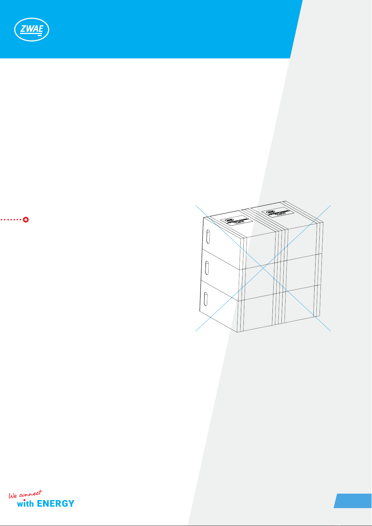
1.1. Unpacking and inspection .............................. 4
1.2. Storage and transport.................................. 5
2. DESCRIPTION ........................................ 5
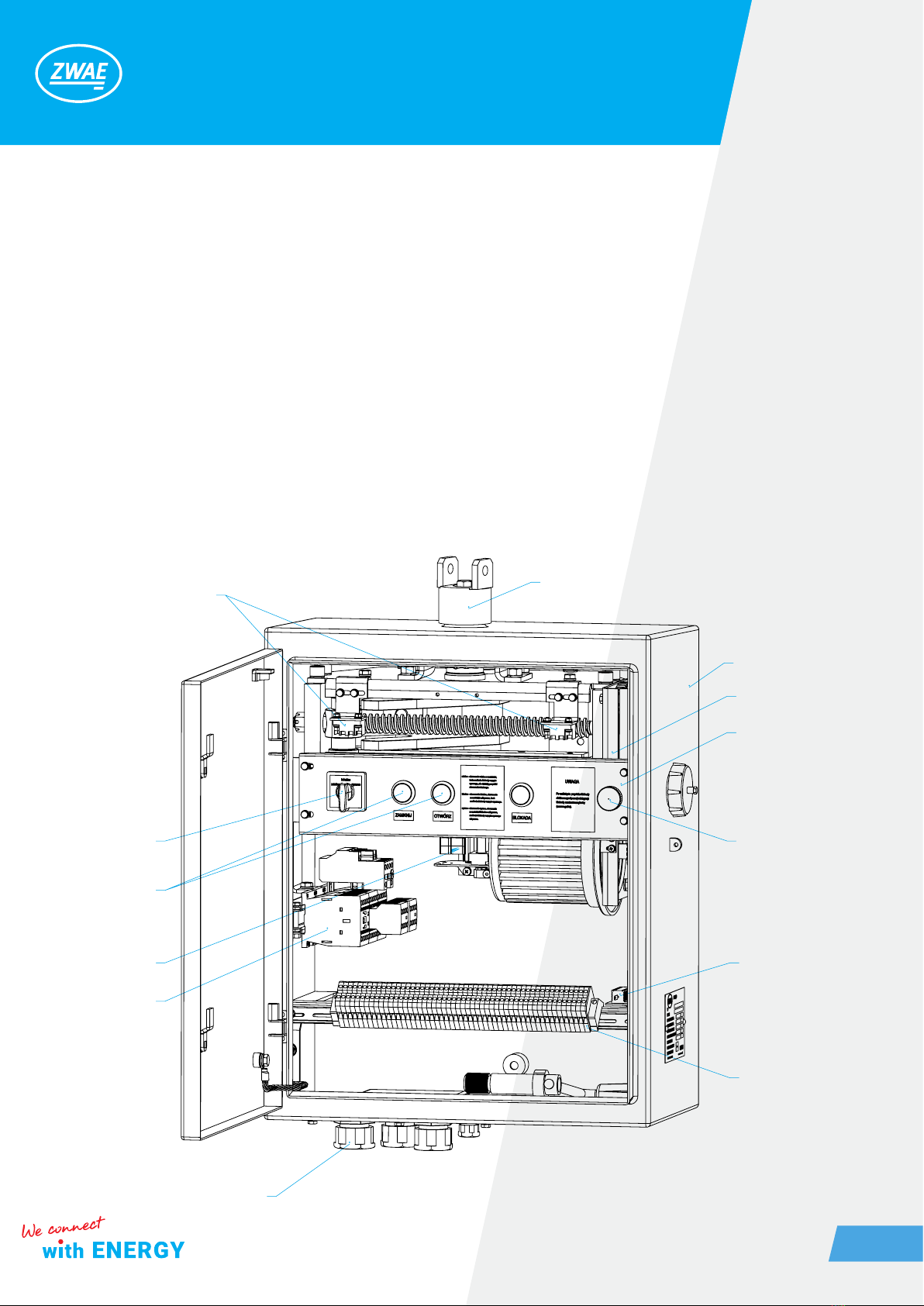
2.1. Construction and principle of operation . .................. 6
2.2. Housing.............................................. 7
2.3. Driving mechanism .................................... 7
2.4. Climatic conditions .................................... 7
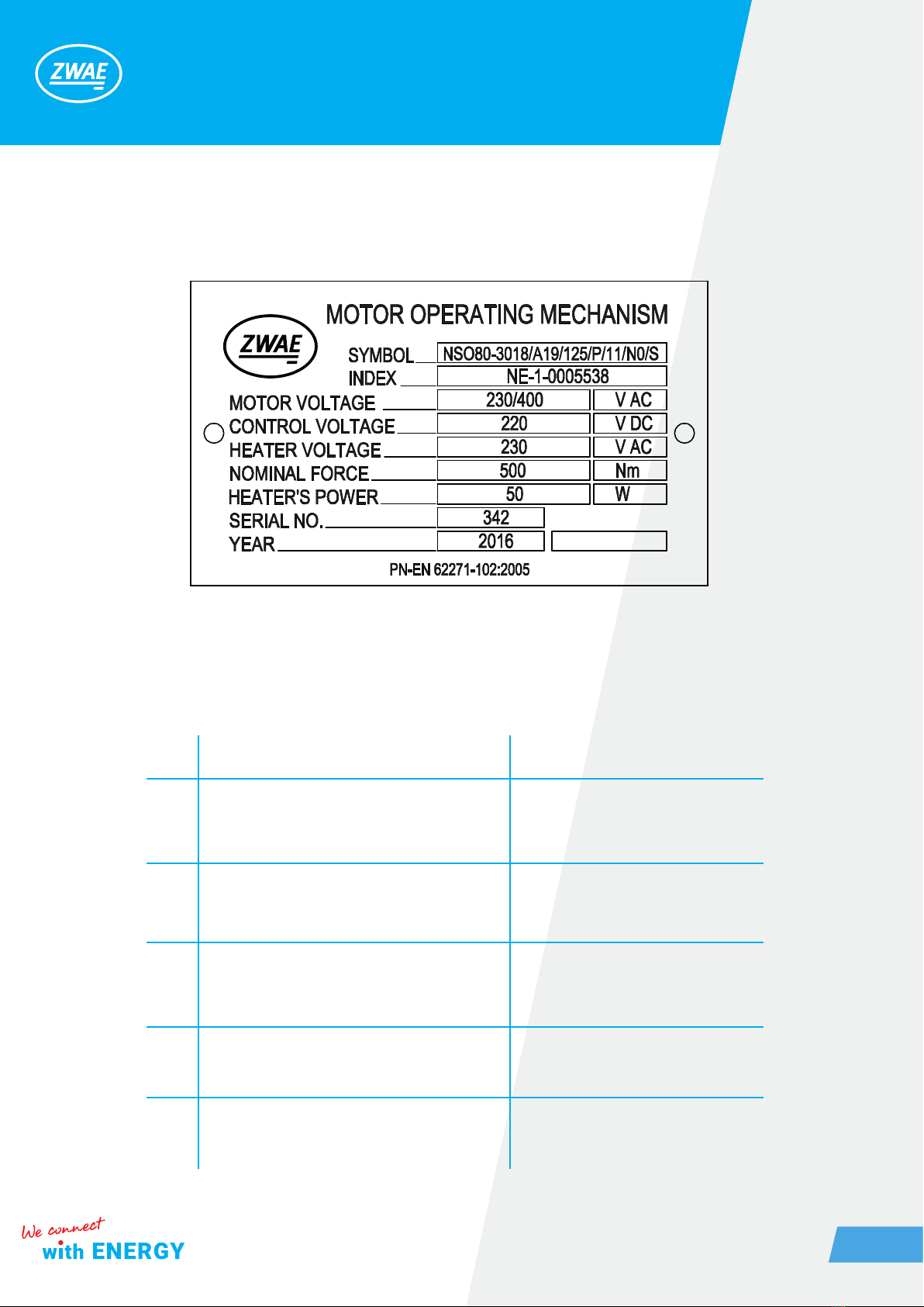
2.5. Nameplate ........................................... 8
2.6. Basic technical parameters ............................. 8
3. INSTALLATION AND ADJUSTMENT ...................... 10
3.1. Coupling with disconnectors ONIII 110 and 220kV ......... 10
3.2. Protective earthing connection.. . . . . . . . . . . . . . . . . . . . . . . . . . 10
3.3. Connection of control and auxiliary circuits .. . . . . . . . . . . . . . . 10
3.4. Tests before rst run ................................... 11
4. OPERATING MANUAL ................................. 11
4.1. Manual maneuvring ................................... 11
4.2. Local maneuvring ..................................... 11
4.3. Remote maneuvring ................................... 11
5. INSPECTION AND MAINTENANCE ....................... 12
5.1. Visual inspection ...................................... 12
5.2. Spare parts and recommended maintenance materials ..... 12
5.3. Periodic inspections ................................... 12
6. DIMENSIONAL DRAWING (STANDARD VERSION - 192°) ..... 13
7. UTILIZATION ......................................... 14

Zakład Wytwórczy Aparatów Elektrycznych Sp. z o.o.
4
1. TRANSPORT
1.1. Unpacking and inspection
Immediately after receiving the operating mechanism the recipient should check delivery compliance with the
packing list. Then the recipient should check whether the operating mechanism has not been mechanically
damaged during transport and the data on the nameplate match the order.
The operating mechanism is transported in cardboard box. They are delivered to the recipient in completely
assembled condition.
The operating mechanisms are delivered to the customer on a pallet (gure below). We suggest moving card-
boards by grabbing the tapes used to pack the operating mechanisms.
Tape

Zakład Wytwórczy Aparatów Elektrycznych Sp. z o.o.
5
1.2. Storage and transport
The operating mechanisms can be transported to the place of storage and installation by any means of trans-
port, provided that they are protected against moisture
During transport, the operating mechanisms should be secured against shifting and colliding with each other
or with vehicle parts. An additional protection for longer transport is a bag with moisture absorbing substance.
It should be removed from the operating mechanism before energizing the heater.
It is forbidden to store the operating mechanisms on their backs in a stacked manner. The operating mecha-
nisms should be positioned vertically as shown in the drawing in section 1.1. This is the only acceptable drive
storage system.
2. DESCRIPTION
NSO80 motor operating mechanisms are intended for maneuvering HV outdoor disconnectors and earthing
switches which angular displacement is up to 192° and both closing and opening operations anti-torque is up
to 800 Nm. The operating mechanisms are compatible with disconnectors and earthing switches produced
by ZWAR, operating at 110, 220 and 400 kV voltage (e.g. ONIII110..., ONI220, ONS..., UNIII110...). They replace
manual or pneumatic operating mechanisms as an upgrade of existing HV disconnectors.
CAUTION! When storing the operating
mechanisms, protect against moisture
until the heater will be energized.

Zakład Wytwórczy Aparatów Elektrycznych Sp. z o.o.
6
2.1. Construction and principal of operation
1. housing,
2. multi-stage gearing mechanism,
3. control panel,
4. control mode switch,
5. control buttons,
6. electromagnetic locking,
7. auxiliary contact switch (NO + NC),
8. heater,
9. terminal strip for connecting control and power circuits,
10. limit switches,
11. motor supply control system,
12. cable gland,
13. driving shaft.
13
1
3
6
9
8
12
11
7
4
55
10
2

Zakład Wytwórczy Aparatów Elektrycznych Sp. z o.o.
7
2.2. Housing
The housing is made of aluminium metal sheet, grade PA4, covered by powder painting epoxy color. Doors are
stuffed with silicone seal. The construction of housing is on protection level IP55 with simultaneous ventilation
of the interior air. It has been achieved thanks by labyrinth seal of drive shaft's output on the top of housing and
using net-protected gland hole in the bottom of housing.
2.3. Driving mechanism
Driving mechanism consists:
• electric motor,
• multi-stage gearing,
• helical gear,
• gearing.
The electric motor drives a lead screw through a two-stage gearing. As a result of rotation of the screw, the
nut mounted on the screw moves along the screw causing rotation of the cooperating forks. A gear wheel is
mounted on the shaft of the fork, cooperating with the gear mounted on the driving shaft. As a result of using
a helical gear unit, the angle of rotation of the output shaft is limited to 192 °. The maximum torque is about
800 Nm.
2.4. Climatic conditions
Operating mechanisms are dedicated to outdoor switchgears in the following conditions:
a) temperature (from – 50°C to + 40°C),
b) air humidity (up to 100% at 20°C),
c) altitude (up to 1000 m),
d) wind speed (up to 30 m/s).

Zakład Wytwórczy Aparatów Elektrycznych Sp. z o.o.
8
2.6. Nameplate
2.6. Basic technical parameters
No. Parameter Value
1.
Rated voltage / rated current:
- squirrel-cage motor
- series motor
3x 400 VAC / 4,5 A
220 VDC / 4 A
110 VDC / 10 A
- contactor coil of motor supply voltage
control (depending on motor rated voltage)
220 VDC
110 VDC
- contactor coil
220 VDC
230 VAC
110 VDC
110 VAC
- heater 230 VAC
220 VDC
- electromagnetic lock 220 VDC
110 VDC
IP55

Zakład Wytwórczy Aparatów Elektrycznych Sp. z o.o.
9
No. Parameter Value
2.
Rated power:
- squirrel-cage motor
- series motor
750 W
500 W
- contactor coil 7W
- heater 25W
- electromagnetic coil 7W
3.
Shaft torque
- rated
- maximum
300/500/1000 Nm
500/800/1600 Nm
4. HV switching time 7s; 11s; 16s
5. Main shaft angular displacement 90°; 125°; 192°
6. Maximum conductor cross section 4 mm2
7. Enclosure protection rating IP 55
8. Operating mechanism’s weight ca. 56 kg
9. Rated mechanical strenght 2000 cycles

Zakład Wytwórczy Aparatów Elektrycznych Sp. z o.o.
10
3. INSTALLATION AND ADJUSTMENT
3.1. Coupling with disconnectors ONIII 110 and 220kV
For coupling operating mechanism with disconnectors is used coupling shaft with a joint.
The end of the shaft is adapted to a particular type of apparatus. To fasten the operating mechanism are used
lattice structures adapted to the customer's needs.
3.2. Protective earthing connection.
For earth connection is used a terminal shown on dimensional drawing. The terminal consists M12 screw and
a washer. The cross-section of the rail connecting operating mechanism to the switchgear's earth connections
ought to be chosen in accordance with legal regulation in force.
Prior to connecting of protective grounding to the operating mechanism’s housing, carefully clean the earthing
terminal's surface. At the end of earthing rail ø13 hole for fastening screw ougth to be drilled. After smoothing
the surface and lubricating the hole, using petroleum jelly, it's allowed to assembly the rail to earthing terminal,
with paying attention to precise bolting on the screw.
3.3. Connection of control and auxiliary circuits
Control cable should be entered into housing through the gland in operating mechanism's duct plate. Connec-
tion of control cable's wires with an operating mechanism's terminal strip should be performed in accordance
with proper switchgear's project. When connecting the motor supply voltage, pay special attention to maintain
correct phase sequence.
The electrical scheme is set individually, its paper version is supplied with the operating mechanism and its
number is indicated on the nameplate.

Zakład Wytwórczy Aparatów Elektrycznych Sp. z o.o.
11
3.4. Tests before rst run
Before putting the operating mechanism into service, the quality of its assembly and the correct interaction
with the apparatus must be checked. For that purpose, 10 - 20 electrically controlled shifts should be made,
carefully observing the interaction of the parts. In the case of any irregularities in the operation of the operat-
ing mechanism or the apparatus cooperating with it, a re-adjustment of the respective assemblies should be
carried out and the tests should be repeated.
4. OPERATING MANUAL
4.1. Manual maneuvring
Set control mode switch in 'manual' position. In that switch's position, remote and local control is disconnect-
ed. Manual drive's electromagnetic locking is ready to work.
In order to start manual drive one should:
• unscrew manual crank’s socket cap (nut on the right side of operating mechanism);
• push “blockade” button;
• pull mechanical lock (black knob);
• release “blockade” button;
• insert the crank;
• turn the crank clockwise or counter-clockwise until the nut on the screw reaches the position where it switch-
es the microswitch;
• pull mechanical lock (black knob);
• pull out the crank;
• skrew the crank’s socket cap.
4.2. Local maneuvring
Set control mode switch in 'local' position. In that switch's position, remote control is disconnected and man-
ual drive's locking is not power supplied. Local control's buttons are working. Pressing „on” button causes
apparatus closing. Pressing „off” buttong causes apparatus opening. Improper buttons using does not cause
apparatus damage or improper functioning.
4.3. Remote maneuvring
Set control mode switch in “remote” position. In this position buttons are unavailable and there is no power
supply to the manual drive’s locking.

Zakład Wytwórczy Aparatów Elektrycznych Sp. z o.o.
12
5. INSPECTION AND MAINTENANCE
5.1. Visual inspection
It is recommended to carry out visual inspections once a year and after each failure or short circuit in the
switchgear.
Check in particular:
a) condition of earthing terminal,
b) condition of coupling mechanisms,
c) condition of external parts (housing),
d) connection of wires with terminal strip, xing of limit switches.
5.2. Spare parts and recommended maintenance materials
The use of high-quality components and operational experiences indicate the long service life of operating
mechanisms (about 40 years). In case of damage to the operating mechanism due to improper assembly or
operation, there is a possibility of paid repair by the manufacturer.
WHITE PHARMACEUTICAL PETROLEUM JELLY (acid-free) used for lubrication of electric contacts (earthings,
contacts of HV switches);
PROTECTIVE LUBRICANT TDM, in accordance with PN-64/C-96146 used for maintenance metal surfaces
(articulated shaft components and coupling mechanism).
5.3. Periodic inspections
Periodic and maintenance inspections should be carried out once every 5 years. During inspection and main-
tenance the using of energetic devices rules and health and safety at work rules have be respected to protect
carrying out the job maintenance personnel.
Check in particular:
• condition of the earthing terminal and earthing installation,
• condition of mechanisms, bearings and connection components,
• correctness of reaching limit positions,
• condition of auxiliary switches contacts,
• condition of anti-corrosion protective coatings,
• adhesion of the door cover’s sealing to the housing edge,
• heater unit.

Zakład Wytwórczy Aparatów Elektrycznych Sp. z o.o.
13
6. DIMENSIONAL DRAWING (STANDARD VERSION - 192°)
max. 18°
186
490
540
~660
677
612
225
max. 18°
2x M16
260
192
120210
50
163,5
max. 18°
max. 18°
16
322
gland
152
184
94
144
194
188

7. UTILIZATION
NSO80 type operating mechanisms are made of materials that are recyclable. The main materials from which
the operating mechanisms are built are:
• steel (painted, galvanized);
• aluminium;
• plastics (epoxy mix, polyamide).
The operating mechanisms do not contain any dangerous substances. In accordance with applicable regula-
tions, it is possible to return a worn-out, complete disconnector to the manufacturer.
Zakład Wytwórczy
Aparatów Elektrycznych Sp. z o.o.
Gdańska 60, 84-300 Lębork
POLAND
Address of correspondence:
Kębłowo Nowowiejskie, ul. Łąkowa 2
84-351 Nowa Wieś Lęborska
POLAND
tel.: +48 59 863 36 15
www.zwae.com.pl
Zakład Wytwórczy Aparatów Elektrycznych Sp. z o.o.
Table of contents
Other ZWAE Industrial Equipment manuals
Popular Industrial Equipment manuals by other brands

Viessmann
Viessmann N Spanbridge Operation manual

Rockwell Automation
Rockwell Automation MagneMotion MagneMover LITE Original instructions

ABB
ABB TPS44-F31 Operation manual

Zimmer
Zimmer GEP9000 Series Installation and operating instructions

Once
Once BioShift instruction manual

Wilo
Wilo WiBooster Installation and operating instructions

Phoenix Contact
Phoenix Contact UM EN FLX ASI SYS PRO INST user manual

SEW-Eurodrive
SEW-Eurodrive MOVIMOT MM D Series manual

Hasco
Hasco Z169 Series Mounting instructions

MultiBlast
MultiBlast PRO 1200W manual

croydon
croydon TI15-250001 C2 instruction manual

Maschinenfabrik Reinhausen
Maschinenfabrik Reinhausen TAPCON 250 installation instructions