ZWAE NSW30 Manual
Installation and Service Manual
Zakład Wytwórczy Aparatów Elektrycznych Sp. z o.o.
NSW30
Motor Operating Mechanism
Manual DTR.05.04.03.EN

Zakład Wytwórczy Aparatów Elektrycznych Sp. z o.o.
2
zwae.com.pl
WARNING!
During the operation of electrical equipment, certain parts of
these devices are normally under dangerous voltage, and mech-
anical parts, also remotely controlled, can move quickly.
Failure to follow the warning instructions can result in serious
personal injury or material damage.
Only suitably qualied personnel can work on or near the device.
These personnel must know exactly all safety rules and main-
tenance rules in accordance with these instructions.
The trouble-free and safe operation of this device requires prop-
er transport, proper storage, construction and assembly as well
as careful service and maintenance.

Zakład Wytwórczy Aparatów Elektrycznych Sp. z o.o.
3
Spis treści
1. TRANSPORT ........................................ 4
1.1 Unpacking and inspection............................... 4
1.2. Transport and storage ................................. 4
2. Description .......................................... 4
2.1. Cosntruction and principle of operation. .................. 4
2.2. Housing box .......................................... 5
2.3. Driving mechanism .................................... 5
2.4. Environmental conditions............................... 5
2.5. Nominal plate......................................... 6
2.6. Technical dat . ........................................ 6
3. ADDITIONAL EQUIPMENT .............................. 7
3.1. Electromagnetic interlock. . . . . . . . . . . . . . . . . . . . . . . . . . . . . . . 7
3.2. Control system in box ................................. 8
3.3. Control system on TH-35 bar5 .......................... 8
3.4. Coupling joint ........................................ 9
3.5. Coupling rod ......................................... 9
3.6. Angular gears......................................... 10
3.7. Disconnector gears ................................... 11
4. INSTALATION AND ADJUSTMENT......................... 11
4.1. Assembling to the supporting construction................ 11
4.2. Assembling on MV switch .............................. 12
4.3. Coupling with rod assembling on the main shaft
of MV switch ............................................. 12

Zakład Wytwórczy Aparatów Elektrycznych Sp. z o.o.
4
4.4. Connecting protective grounding.. ....................... 12
4.5. Connecting control and supply circuits.................... 12
4.6. Adjusting the rotation angle of the output shaft. ........... 13
4.7. Tests before putting into service ......................... 13
5. EXPLOITATION ....................................... 14
5.1. Manual control........................................ 14
6. PERIODIC INSPECTIONS AND CONSERVATIONS ............ 16
6.1. Visual inspection ...................................... 16
6.2. Spare parts and recommended maintenance materials. . .... 16
7. DIMENSION DRAWING OF THE OPERATING MECHANISM .... 17
8. DIMENSION DRAWING OF THE CONTROL BOX ............. 17
9. WIRING DIAGRAM OF NSW30-3 – MOTOR WITH
PERMANENT MAGNETS ................................. 18
10. WIRING DIAGRAM OF NSW30-4 – SERIAL MOTOR ......... 19
11. UTILIZATION ....................................... 20

Zakład Wytwórczy Aparatów Elektrycznych Sp. z o.o.
5
1. TRANSPORT
1.1. Unpacking and inspection
Immediately after receiving the drive, check the delivery compliance with the shipping specication. Then
check whether the drive has not been mechanically damaged during transport and the data on the nameplate
with the order
The drive is delivered in a cardboard package. Drives are delivered to the recipient completely assembled.
1.2. Storage and transport
For storage and installation, the drives can be transported by any means of transportation provided they are
protected from moisture. During transport, the drives should be secured against moving and colliding with
each other or parts of the vehicle.
2. DESCRIPTION
NSW30 motor drives are designed for cooperation with disconnectors, disconnectors and earthing switches
of medium voltage in indoor conditions. The use of the drive allows remote or local control of the switch
installed in the switchgear cubicle. In a simple way, without any additional changes in the existing switch-
gear, you can replace the existing pneumatic or manual drives of the NRK type, thereby introducing a new
standard of operation and safety (remote control option, local or manual)
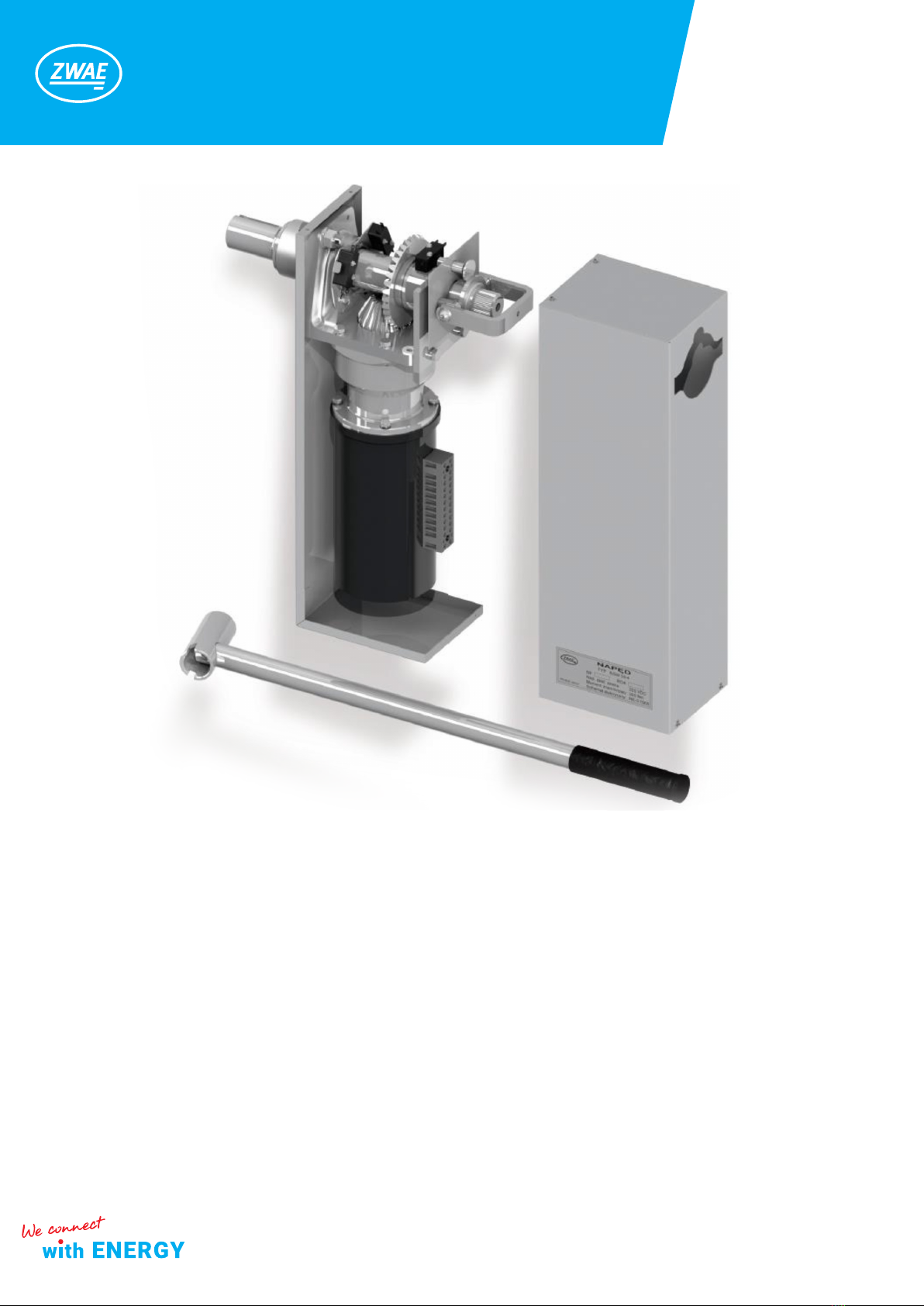
2.1. Construction and principle of operation.
1. housing box,
2. core,
3. gear,
4. motor,
5. angular gear,
6. output shaft,
7. limit switch,
8. terminal block,
9. lock handle enabling switching to
manual or motor operation,
10. manual lever
11. microswitch of electrical blockade.
9
10
8
4
3
6 1 2 7 5 11
Zakład Wytwórczy Aparatów Elektrycznych Sp. z o.o.
6
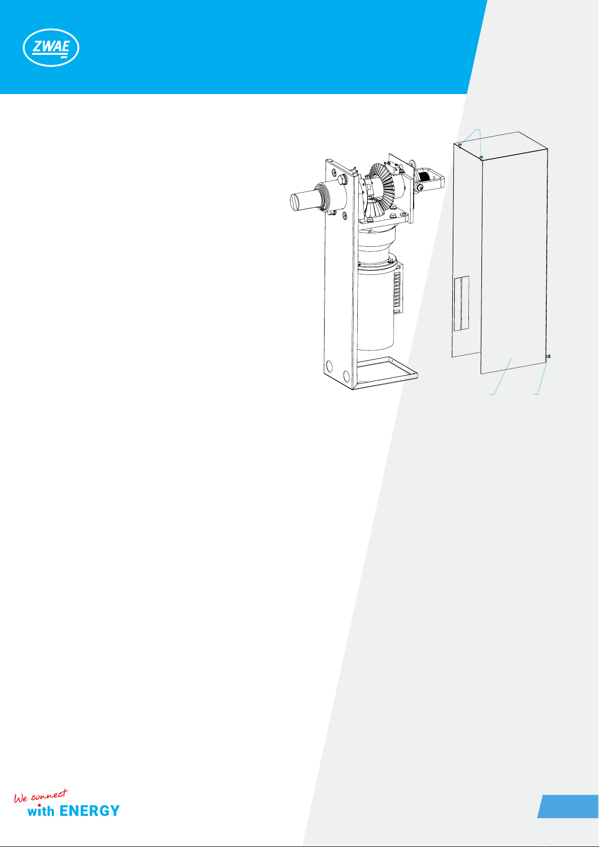
2.2. Housing box
The housing box is made of steel sheet,
covered with a layer of epoxy powder paint.
The housing cover is attached to the corp behind
using four self-tapping screws [12]. In the bottom
parts of the housing, on both sides, are located
embossments with a diameter of 14 mm allowing
bringing wires to the control system.
1.casing
2. sheet metal srews
2.3. Driving mechanism
Driving mechanism includes:
• DC electric motor
• Multistage transmission gear
• angular gear.
An electric motor drives a bevel gear through a three-gear gear.
As a result of the gear transmission, the maximum drive torque is approx. 300Nm, and the angle of rotation
of the output shaft is limited by the limit switches to 220 °. The casing is made of steel sheet, covered with a
layer of epoxy powder paint. The housing cover is attached to the body by means of four self-tapping screws
[12]. In the lower part of the casing, a cable gland with a diameter of 14 mm is provided, enabling the supply of
control and supply wires.
2.4. Environmental conditional
The drives are recommended to be used indoors, in an atmosphere free from aggressive chemical agents, at
ambient temperatures of -5 to + 40 ° C and relative humidity not exceeding 70%.
2
12

Zakład Wytwórczy Aparatów Elektrycznych Sp. z o.o.
7
2.5. Nominal plate
2.6. Technical data
Lp. Parameter Value
1. Type NSW30-3 NSW30-4
2. Nominal voltage
110 VDC
110 VAC
24 VAC
220 VDC
230 VAC
3. Nominal current
4,9A/220V
5A/220 V
19 A/24 V
4,9 A/220 V
4. Nominal power 300W
5.
Torque:
- nominal
- maximum
150 Nm
300 Nm
6. Switching time ca. 5s
7. Maximum diameter of wires 4 mm2
8. Weight ca 10kg
9. Mechanical endurance 2000 cycles

Zakład Wytwórczy Aparatów Elektrycznych Sp. z o.o.
8
3. ADDITIONA EQUIPMENT
3.1. Electromagnetic interlock
Zakład Wytwórczy Aparatów Elektrycznych Sp. z o.o.
9
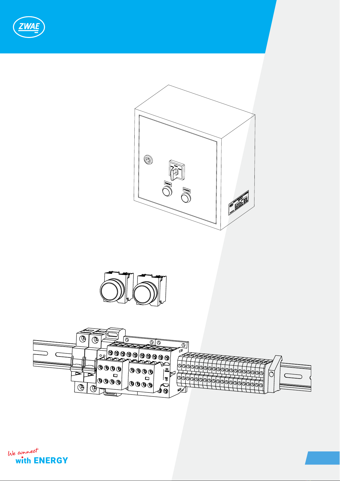
3.2. Control system in the box
3.3. Control system on TH-35 bar

Zakład Wytwórczy Aparatów Elektrycznych Sp. z o.o.
10
3.4. Coupling joint
3.5. Coupling rod
Standard
Insulated
StrengthenedStandard
Other manuals for NSW30
1
Table of contents
Other ZWAE Industrial Equipment manuals


