Zakład Wytwórczy Aparatów Elektrycznych Sp. z o.o.
4
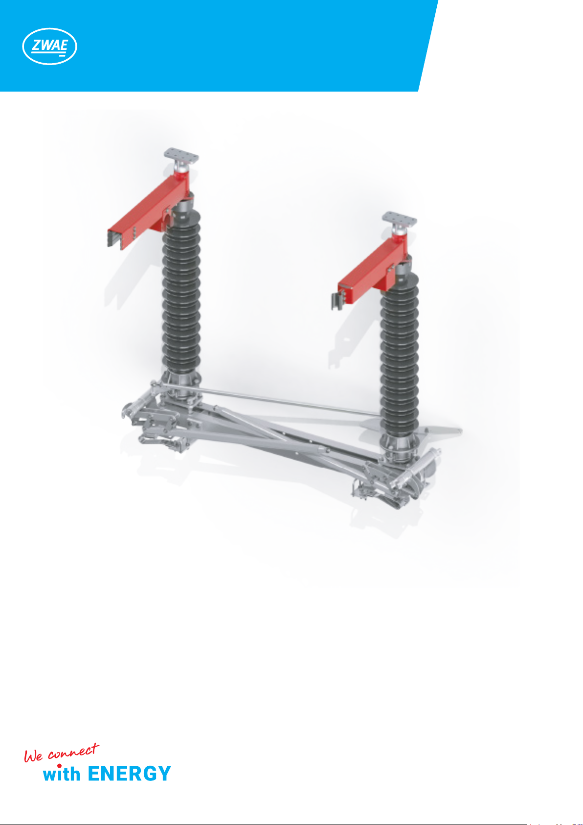
1. DELIVERY METHOD
ONIII-123 outdoor disconnectors are delivered to the customer partially assembled. The bases of individual dis-
connector poles, current paths, coupling elements, drives and structures for suspending the drives are placed in
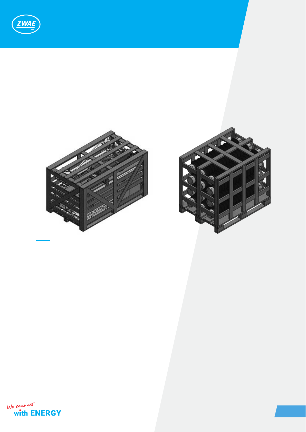
a wooden crate (1 crate contains 3 disconnector poles). The insulators are delivered in a separate wooden box.
2. DISCONNECTOR’S RECEIPT
Check if the disconnector and the accessories, meet the shipping specications. You should also check if the
delivery is not mechanically damaged. In the event of any non-compliance or damage, notify the manufacturer
immediately.
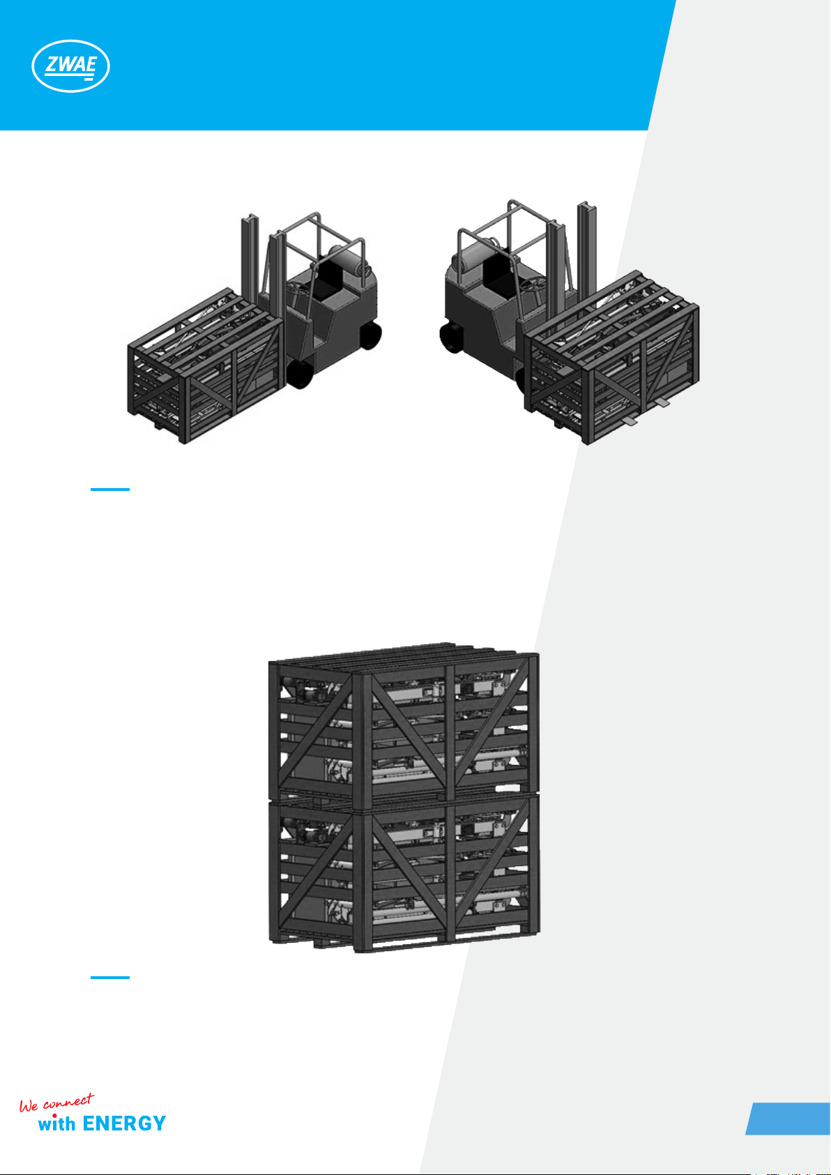
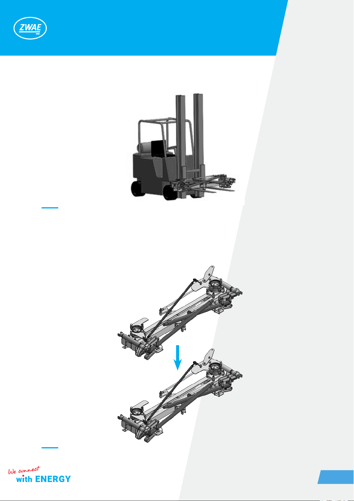
3. MOVING
Crates with ONIII-123 disconnector parts can be safely moved with a forklift. It is allowed to lift the crates one
at a time, by the pallet base, on either side of the crate.
Fig. 1, 2. Shipping crates. Left – disconnectors’ parts, right – insulators