2N Lift8 User manual

The 2N TELEKOMUNIKACE a.s. is a Czech manufacturer and supplier of telecommunications
equipment.
The product family developed by 2N TELEKOMUNIKACE a.s. includes GSM gateways, private
branch exchanges (PBX), and door and lift communicators. 2N TELEKOMUNIKACE a.s. has
been ranked among the Czech top companies for years and represented a symbol of
stability and prosperity on the telecommunications market for almost two decades. At
present, we export our products into over 120 countries worldwide and have exclusive
distributors on all continents.
2N is a registered trademark of 2N TELEKOMUNIKACE a.s. Any product and/or other
®
names mentioned herein are registered trademarks and/or trademarks or brands protected
by law.
2N TELEKOMUNIKACE a.s. administers the FAQ database to help you quickly find
information and to answer your questions about 2N products and services. On
www.faq.2n.cz you can find information regarding products adjustment and instructions for
optimum use and procedures „What to do if...“.
2N TELEKOMUNIKACE a.s. hereby declares that the 2N product complies with all
®Lift8
basic requirements and other relevant provisions of the 1999/5/EC directive. For the full
wording of the Declaration of Conformity see the CD-ROM (if enclosed) or our website at
www.2n.cz.
The 2N TELEKOMUNIKACE a.s. is the holder of the ISO 9001:2009 certificate. All
development, production and distribution processes of the company are managed by this
standard and guarantee a high quality, technical level and professional aspect of all our
products.
Content

Content
1. Product Introduction . . . . . . . . . . . . . . . . . . . . . . . . . . . . . . . . 5
1.1ProductDescription ..............................................6
1.2ComponentsandAssociatedProducts ...............................8
1.3Upgrade .......................................................22
1.4TermsandSymbolsUsed .........................................23
2. Description and Installation . . . . . . . . . . . . . . . . . . . . . . . . . . 24
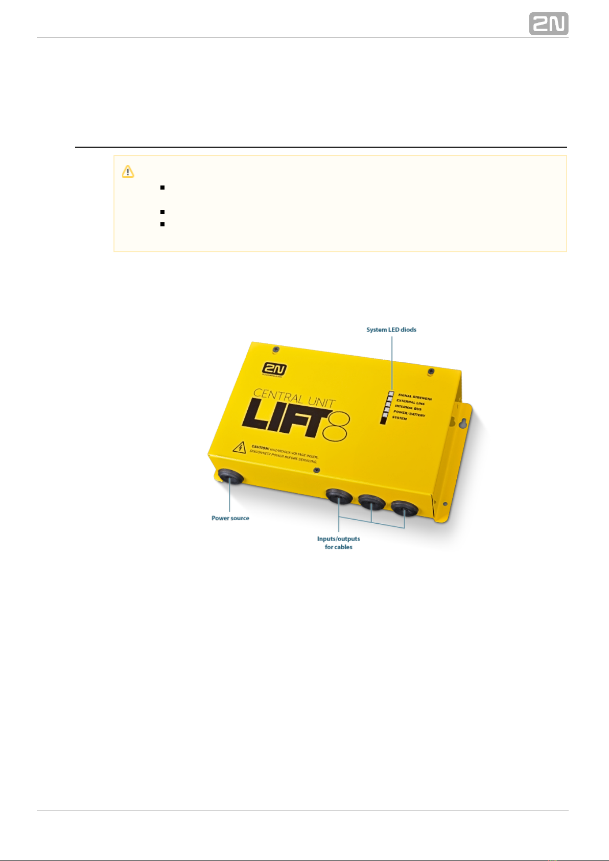
2.1PSTN/GSM/UMTS/VoIPCentralUnit .................................25
2.2Splitter ........................................................39
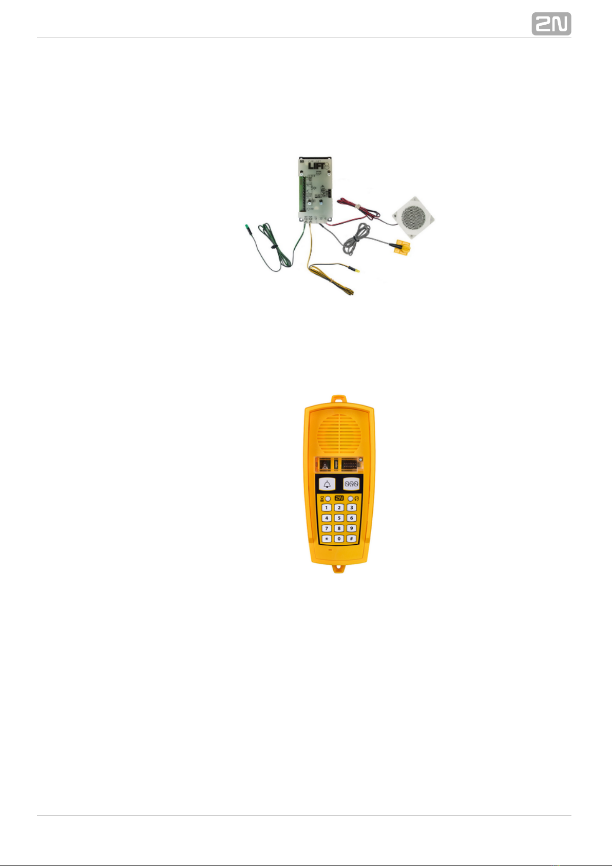
2.3AudioUnit–CabinUniversal .......................................45
2.4AudioUnit–MachineRoom ........................................58
2.5AudioUnit–Shaft ................................................63
2.6AudioUnit–Compact .............................................68
2.7PSTNModule ...................................................79
2.8GSM/UMTSModule ..............................................81
2.9VoIPModule ....................................................83
2.10AudioUnit–Fireman ............................................85
2.11I/OModule ....................................................107
2.12CameraModule ................................................113
2.13RS232Module .................................................126
2.14AudioUnit–ShaftAntivandal ......................................131
3. System Configuration . . . . . . . . . . . . . . . . . . . . . . . . . . . . . . . 136
3.1Lift8Programming ...............................................137
3.2TableofParameters(FW1.10.0) ....................................140
3.3SMSConfiguration ...............................................154
4. Function and Use . . . . . . . . . . . . . . . . . . . . . . . . . . . . . . . . . . 157
4.1UserInstructions .................................................158
4.2ControlCentreInstructions .........................................160
4.3FunctionDescription(forAdvancedUsers) ............................162
4.4CallConfirmationTypes ...........................................166
4.5LiftBlockingFunction .............................................169
4.6Four-LiftVersion .................................................170
4.7IntercomFunction ................................................172
4.8SystemCompletenessCheck ......................................175
5. Service Tool . . . . . . . . . . . . . . . . . . . . . . . . . . . . . . . . . . . . . . . 177
5.1InstallationandLogin .............................................178
5.2IntroductiontoApplication .........................................181

5.2IntroductiontoApplication ........................................181
5.3Use ...........................................................189
6. Server . . . . . . . . . . . . . . . . . . . . . . . . . . . . . . . . . . . . . . . . . . . . 210
6.1InstallationandLicensing ..........................................211
6.2Use ...........................................................214
7. Control Panel . . . . . . . . . . . . . . . . . . . . . . . . . . . . . . . . . . . . . . 218
7.1InstallationandLogin .............................................219
7.2IntroductiontoApplication .........................................222
7.3Use ...........................................................227
8. Communicator . . . . . . . . . . . . . . . . . . . . . . . . . . . . . . . . . . . . . 264
8.1InstallationandLogin .............................................265
8.2IntroductiontoApplication .........................................268
8.3Use ...........................................................272
9. Service Tool for Android . . . . . . . . . . . . . . . . . . . . . . . . . . . . 282
9.1InstallationandConnection ........................................285
9.2Use ...........................................................290
10. Maintenance . . . . . . . . . . . . . . . . . . . . . . . . . . . . . . . . . . . . . 297
10.1OperationInterruptionandBatteryReplacement .......................298
10.2FirmwareUpgrade ..............................................300
11. Technical Parameters . . . . . . . . . . . . . . . . . . . . . . . . . . . . . . 301
12. Supplementary Information . . . . . . . . . . . . . . . . . . . . . . . . . 304
12.1Troubleshooting ................................................305
12.2ListofAbbreviations .............................................306
12.3Regulations ....................................................307
12.4GeneralInstructionsandCautions ..................................308

52N TELEKOMUNIKACE a.s., www.2n.cz
®
1. Product Introduction
In this section, we introduce the product, outline its application options and2N Lift8
®
highlight the advantages following from its use.
Here is what you can find in this section:
1.1 Product Description
1.2 Components and Associated Products
1.3 Upgrade
1.4 Terms and Symbols Used

62N TELEKOMUNIKACE a.s., www.2n.cz
®
1.1 Product Description
Basic Features
Up to 8-lift connectivity
Lift cabin, shaft and machine room voice audio units
Optimum acoustic properties
Rechargeable built-in backup battery
Easy control and configuration – voice response system
Check Call function
Lift blocking during connection failure
Internal communication – Triphony
Telephone/PC-based configuration (via USB or Internet)
USB interface
User message recording option
Local control centre (Intercom)
Fireman function
Basic Description
2N Lift8
®( ) is a communication system with a function similar to an intercom. TheL8
system voice audio units are linked to a common bus (pair of wires), connected to a
splitter. The splitter is always connected to a central unit (CU), which controls the
system operation and provides connection with the control centre. It is possible to
connect up to 40 audio units to the bus. The CU contains an internal splitter.
Each splitter is uniquely identified: by lift number 1 to 8. The audio units are connected
to the splitters and located on the shaft bottom, in the cabin interior, on the cabin roof
and in the machine room. The machine room can be shared by multiple lifts.audio unit
The contains an easily replaceable backup battery pack (lead rechargeable battery). CU
The is responsible for battery charging and status monitoring. It indicates theCU
charging state, signal strength, telephone line state, bus state core state via five colour
LEDs. It is also equipped with a USB interface for comfortable configuration, voice
message recording and software upgrade.
The can be connected via: GSM, UMTS, PSTN or VoIP. CU

82N TELEKOMUNIKACE a.s., www.2n.cz
®
1.2 Components and Associated Products
2N Lift8 System Components
®
918600 2N Lift8 Central Unit
®
Central UnitFigure: 2N Lift8
®
For connection of up to 8 lifts to a GSM/UMTS/PSTN line. Including a power EURO cable
and rechargeable battery. USB interface for configuration.
Notification
The components of the system cannot be used outside this2N®Lift8
system.
The audio units cannot be connected to a telephone line without the !CU
When shared by multiple shafts, the audio units cannot be connected
without the and splitters.CU

92N TELEKOMUNIKACE a.s., www.2n.cz
®
918620E 2N Lift8 Splitter
®
SplitterFigure: 2N Lift8
®
For – lift audio unit interconnection.CU
918610E 2N Lift8 Audio Unit – Cabin Universal
®
(Normal version)
Audio Unit – Cabin UniversalFigure: 2N Lift8
®
Audio unit electronics for lift cabin building in. Including speaker and microphone
(HandsFree). Connection terminals for all prescribed elements and door opening signal
input (optional).

102N TELEKOMUNIKACE a.s., www.2n.cz
®
918610EX 2N Lift8 Audio Unit – Cabin Universal – Cable Version
®
Contains LED, microphone and speaker connected to cables.
Audio Unit – Cabin Universal – Cable VersionFigure: 2N Lift8
®
918611E 2N Lift8 Audio Unit – Machine Room/Control Centre
®
Audio Unit – Machine Room/Control CentreFigure: 2N Lift8
®
Audio unit for the machine room/control centre. Contains receiver (optional) and
keypad for easy control. Makes it possible to communicate with other system audio
units and configure the without a PC. Equipped with an external siren connector.CU
Can be shared by multiple lifts (shafts). Robust yellow cover.

112N TELEKOMUNIKACE a.s., www.2n.cz
®
918612E 2N Lift8 Audio Unit – Shaft
®
Audio Unit – ShaftFigure: 2N Lift8
®
Audio unit for cabin roof and shaft or cabin bottom. Robust yellow cover. HandsFree
mode, ALARM button and Triphony, LED indicators. Not intended for use in the cabin.
918613E 2N Lift8 Audio Unit – Compact
®
Audio Unit – CompactFigure: 2N Lift8
®
Robust, heavy-duty design. Standard-sized ALARM button including signage for the
blind and backlit pictograms (hardened glass). Easy cabin wall mounting. Easy 2-wire
connection.

122N TELEKOMUNIKACE a.s., www.2n.cz
®
918615ZK 2N Lift8 Audio Unit – Fireman (1 button)
®
918615E 2N Lift8 Audio Unit – Fireman (knob + 1 push-to-talk
®
button)
Audio Unit – FiremanFigure: 2N Lift8
®
Used for fire fighting operations. Activates top priority calls.
918610FZK 2N Lift8 Audio Unit – Fireman DPS (1 button)
®
918619E 2N Lift8 Audio Unit – Fireman DPS (knob + 1 push-to-talk
®
button)

142N TELEKOMUNIKACE a.s., www.2n.cz
®
Audio Unit - Shaft AntivandalObrázek: 2N® Lift8
A robust, highly resistant audio unit designed for installation on lift cabin roofs and
shaft bottoms, under cabin floors and/or any other places that require communication,
e.g. for lift maintenance purposes. This unit is designed for outdoor applications too.
918621E 2N Lift8 I/O Module
®
I/O ModuleFigure: 2N Lift8
®
Contains logical inputs and switch relays.
918622 2N® Lift8 Camera Module
Camera ModuleFigure: 2N® Lift8
For camera connection (IP, RS232, RS485) to the lift cabin. Every cabin in each shaft
can contain a camera module (up to 8 camera modules in 2N® Lift8).

152N TELEKOMUNIKACE a.s., www.2n.cz
®
918XXX 2N® Lift8 RS232 Module
Obrázek: RS232 Module2N® Lift8
The RS232 module connects the system with the lift control unit. The lift2N® Lift8
control unit transmits a command via RS232 to the Central Unit for processing and
executing.
918650E 2N Lift8 GSM Module
®
GSM ModuleFigure: 2N Lift8
®

162N TELEKOMUNIKACE a.s., www.2n.cz
®
For Central Unit connection via a mobile network. Optional data connection for remote
system configuration.
918651E 2N Lift8 UMTS Module
®
UMTS ModuleFigure: 2N Lift8
®
For Central Unit connection via a mobile network. Optional data connection for remote
system configuration.

192N TELEKOMUNIKACE a.s., www.2n.cz
®
Cooperating 2N Applications
®
918700E 2N Lift8 Service Tool
®
Figure: 2N Lift8
®Service Tool
The is intended for remote supervision and2N Lift8 Service Tool
® application
configuration of the communicators.2N Lift8
®
918700E 2N Lift8 Control Panel
®
Figure: 2N Lift8 Control Panel
®
The application is intended for administration of users, lifts2N Lift8 Control Panel
®
Other manuals for Lift8
11
Table of contents
Other 2N Cell Phone manuals