2N Lift1 Compact Reference guide

EN
2N® Lift1
ComunicatorforLifts
Brief Manual
Issue2,Version1.0 www.2n.cz

EN
Sortiment
PartNo. Description
919640xx Basicmodelformountingbelowthepanel
919618xx Modelwith thefront panel
Extending modules
PartNo. Description
913648E Universal switch –remotely controlledswitchby
DTMF,oneswitchorliftblockingmodulecanbeused.
919649E Liftblocking module– blockstheliftfunctionduring
telephonelinefailures.
919650E Amplifier module –forincreasingvolumeinnoisy
environment
919621E Inductionloop –forpersonswithhearingaid,
includesaself-adhesiveholderand1m cable.
919680E Programming tool – interconnectsLift1 withthe
2N®ServiceToolonthePCforprogramming.
Description
2N®Lift1(hereinafterreferredtoasLift1)isdesignedforcallingtopredefinedphonenumbers.It
isusuallyusedforemergencycall fromlifttothecontrol centre ortothepersonwhotakescare
of thelift.A PSTNoralternative(PBX,GSMgateway)lineisusedforconnectionwiththecontrol
centre.
Thebasicversionisdedicatedformountingbehindtheliftpanel,theremustbeweldedscrewsor
holesformounting.Thespeaker,microphoneandindicatingLEDscanbemountedtothefront
panelofthedeviceorcanbedeliveredseparately withcablestobemountedanywhereonthelift
panelaccordingthedesign(cableversion).Modelwiththecoverpanelincludesthefront,visible
cover,thiscoveroverlapsbordersofthemountinghole.Itdoesn’tneedexactmountingholesand
thedesignofthespaceforspeaker andmicrophoneissolved.
Formountingonthetopofthecabinsurfaceisdesignatedthe2N®Lift1 Compactversion,in
robustmetalcover,whichincludesallpartsneededforfunctionincludingthealarmbutton.The
descriptionisnotpartofthismanual,forinformationcontacttheproducer.
Operation
Press theALARMbuttontoactivateconnection.The"Wait"pictogramgoesonimmediately and
the"Connectionestablished"symbolgoesoutwhencommunicationhasbeensetup.Youcanuse
automaticdialingofuptosixpre-programmednumbers.Communicationisaccompaniedby
factoryannouncementsand/oruserrecordedliftIDmessages.
ServiceandOperatingStaff Instructions
In theAutomaticDialingwithConfirmationmode– defaultsettings:
DTMFcharter: Function
Confirm toLift1 thatthecall wassuccessful.Lift1showsthe
connectionby appropriatepictogram,mutesthecurrently played
announcementandallowsthecall tilltimelimit isexhausted.
Mute theactualautomaticannouncement.

EN
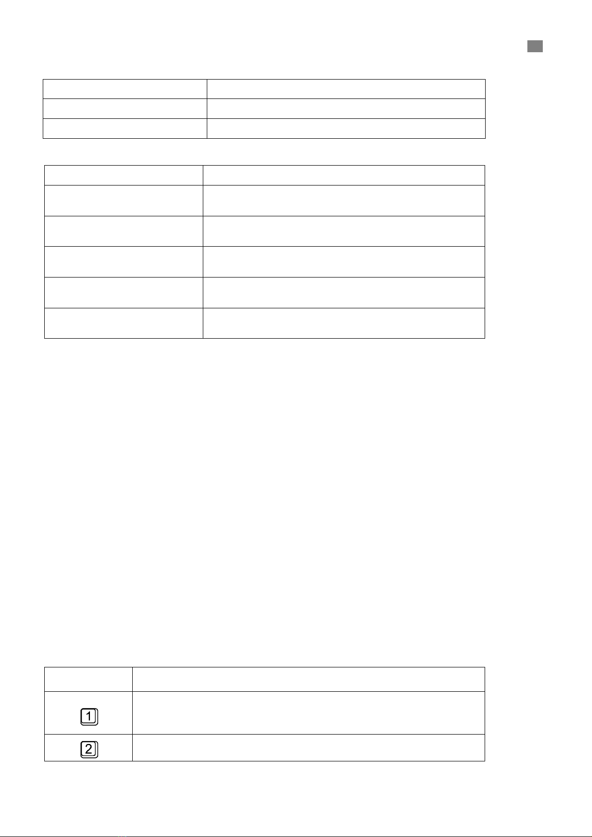
Play theuser messageforliftidentification,if storedinLift1.
or Extend thecall by30 seconds.Canbeusedrepeatedly.
or Terminate thecall.
Identification sending forLiftManager
až , Switchoperating keywordforswitchmuststartwiththisnumbers.
Beforeyou start
InstallationConditions
·Lift1 isnotintendedforoutdoorapplications.
·Astheproductisconnectedtoatelephonelineandmay thusproducelife-endangeringvoltage,
followthesafetyprecautions–referto Safety Precautions.
·NeverconnectLift1 toalineinparallelwithanotherterminaldevice.
·Makesure thattheliftwallisperfectlyflat.
·Makesure thattheliftcabininstallationisincompliancewiththeapplicableliftstandards.
Tips
·Useaportablephonetomakesurethatthetelephonelineworks.
·Makesure thatyouknowthetelephonelinenumber tomakeatestcall.
Mounting
ThebasicmodelofLift1isdesignedformountingtotheliftpanelfrom back side.Four58x122
mm spot-weldedM4 screwsorothermethodusingtheholesinthecorner of thedeviceshouldbe
usedforfixing.Theremustbesufficiently perforatedspeakerarea, theperforationmaynever
exceedthepanelsizetoavoidacousticfault.There shouldn’tbespacebetweentheliftpaneland
thecabinorthegap mustbesealedproperlytoeliminateacousticfaultofthespeaker and
acousticfeedbackbetweenthespeakerandmicrophone.Infront of themicrophonemustbethe
holeinthepanel,recommendeddiameteris2mm orappropriateperforation.WhentheLED
indicatorsonthedeviceare used,infrontofthem mustbeproperapertures,inthiscasethe
modelwithlightguidesissuggestedforbetterperformance.
Thecableversionofthecommunicatorhasthespeaker,mikeandledindicatorsconnectedby
cables,allowingplacementaccordinginstaller needs.
Themodelwiththefrontpanelisnecessarytocutoutshespaceinthecabintoinserttheunit,
thefrontpanelcoversthehole,itisfixedbytwoscrews.
ForlightindicationcanbeusedLEDindicatorsin theunit,externalLEDsdeliveredwiththecable
versionorindicatorsbuild-inbytheliftproducer.Fortheseexternalindicatorscanbeused
switchesintegratedinthedevice,theseswitchesare electrically separatedfromthephoneline.
Externalpower isinthiscasenecessary.
Alldescribedtypesof Lift1usesexternalbuttonAlarm,whichisnotpartofthedelivery andmust
beconnectedtothedevice.Input Cancelcanbeusedforcancelingoftheactivatedalarmbefore
thecallisestablished.InputsAlarm1 andCancelcanbeconfigured,thepositiveornegativelogic
canbesetandelectricalseparationisavailable.InputAlarm2canbeusedasadditionalinputfor
alarmactivationorforendofalarmsignalingactivatedby operatingpersonnel.
Detailsare describedinchapter “Mounting”inuser manual.Pleasereadcarefullythepart“Safety
caution”below!

EN
MountingDrawingforbasicmodel of Lift1
Mountingholes,fourM4spot-
weldedscrewsfrom shaftside
recomended
Perforatedspeaker area, inthe
cabinwallmustbetheperforation
forgoodsoundquality,the
perforatedareamustnotexceed
theLift1 panel
TwooptionalLEDholes,whenthese
LEDsareused,modelwith
lightguidesissuggestedforbetter
performance
Spaceformicrophone,holeor
perforationinthecabinwallis
necessary
Safetycaution
·TheterminalsCancelandAlarm1with contactcontrol,Alarm2,Phoneline,connectorsfor
externalLEDssuppliedfromLift1,externalmicrophone,externalspeaker,inductionloop,
VASAlarm,programmingconnectorandtheboardwithelectronicsare connectedtoa
telephonelinewherelife-endangeringvoltagemayoccur.Connectedswitches,LEDsand
other partsmustbeinstalledwith minimumisolationdistance1.5mm andtheminimum
breakdownvoltage1500V.Thisappliestotheswitchesitselftoo!
·TheDC controlledterminalsare separatedfromthetelephonelineanddonothaveto
meettheisolationrequirementsmentionedabove.
·Makesurethatthecablescannotgetincontactwithsharpedgesduringinstallationto
avoidinsulationdamage.Check theminimumisolationdistanceof1.5mmafter
installationusinganisolationmeterifpossible.
·Themanufacturer shallnotbeheldliableforanyinstallationsmadeinconflictwiththese
instructions.

EN
Electrical Installation
Terminalsdescription
Connector/Name Description
ALARM1
Terminal
DC =voltage
control*)
12–24 VDC,any polarity,
activationbysignalornosignal
statepossible Alarm callactivation
contact
control
normally openornormally closed
contact
ALARM2
terminal
contact
control Normally opencontactonly Alarm2 callorendof
rescuemode
CANCEL
terminal DC =voltage
control*)
12–24 VDC,any polarity,
activationbysignalornosignal
statepossible Alarm calldeactivation
upondooropening
contact
control
normally openornormally closed
contact
Indicatorterminals*) Indicators(illuminatedpictograms)upto24V /2x200mA,
externally supplied,wiringdiagrammustbemaintained
ConnectorsforexternalLED
suppliedfrom Lift1
ExteralLEDconnectedtophone
line– setheSafety caution
Suppliedwithcable
versionofLift1
Connectorforexternal
microphone
Externalmicrophone,tobeplaced
accordinginstaller needs
Suppliedwithcable
versionofLift1
Connectorforexternal
speaker
Externalspeaker,tobeplaced
accordinginstaller needs
Suppliedwithcable
versionofLift1
Connectorforinductionloop Inductionloopforpersonwit
hearingaid Accessoryequipment
Connectors
VASALARM1
VASALARM2
ForVoiceAlarmStation
connection,only oneofthemcan
beusedconcurrently
ActivatesAlarm1 or
Alarm2accordingused
connector
PROGRAMMIGCONNECTOR
USBprogrammingtool for2N®
ServiceToolviaPC
configuration,
firmware,voicemenu
JumperRecoverymode–
accessibleaftercover
replacement
SetthejumpertoONtoactivatetherecoverymodeforFW
upgradewhenever aproblem occurswiththeLift1–2N®
ServiceToolconnection.
Switchcontact*)
Theswitchesare usedforvariablepurposesandare
remotelyDTMF-controlled.Theswitchesarenotdesignedfor
230 V!Switchorliftblockingcontactcanbeused.
Liftblockingcontact*)
Thecontactopenswheneveraphonelinefailureoccurs.It
allowssignalingorliftblocking.
Power foramplifier *) Amplifiermoduleneedsexternalpower source
*)Theseterminalsaresafelyelectricallyisolatedfromthetelephoneline.
TheALARM1terminalblockhelpsactivatealarmcalls.
TheALARM2terminalblock canbeusedforalarm todifferentsetofnumbers,especially with
Voicealarmstation,orforendof alarm setting.Onlyisolatedswitchwithnormally opencontact
canbeused.
TheCANCELterminalblock helpsdeactivateanactivealarm whenthedooropens.Therefore,set
parameter 914toavaluehigherthanthemaximumlifttravellingtime.
FortheAlarm1 andCancelinputcanbeusedswitchbuttonbothwithnormally openedor
normally closedcontacts,isolated.Theisolatedvoltageinputscanbeactivatedby anyvoltage
from12to24V.Thelogicofinputsistobesetby parameters(920forAlarm1,916forCancel).

EN
Terminalsforexternallysuppliedindicatorsarededicatedforconnectinganyindicators
(illuminatedpictograms).Theseterminalsare safelyelectricallyisolatedfromthephoneline,the
usercanconnectanyindicator.Theusedvoltageis12V,eventually24V.Itisnecessarytokeep
thepolarity ofindicators.Maximalcurrentoftheindicatoris200 mA.Whenyouconnectexternal
power source,theinternalLEDscanbeactiveevenwhenthelineisonhook,itallowstosupport
standards(permanentsignalizationtillrescueisdone,linefailuresignaling).Seethewiring
diagramforexternalindicatorsbelow.
Plugsandconnectorsonthebottom sideofLift1

EN
ConnectorsforexternalLEDsuppliedfromLift1andconnectorsforexternalmicrophoneand
speakercanbeusedforconnectingofthesepartsoncables,allowingtheuser toplaceit
accordingtheconstructionof theliftcabin.Thesepartsaredeliveredwith thecableversionof
Lift1.Thesepartsmustbeisolatedforminimumbreakdownvoltage1500 V(seethesafety
caution).InductionloopistheAccessoryequipmentforpersonswithhearingaid,itcanbeused
onlyinveryshortdistancefromtheloop.Whenthewholeliftcabinshouldbecoveredwithsignal,
amplifier forinductionloopmustbeused,formore informationcontactproducer.
ThereispossibletoequipLift1 withuniversalswitchremotely DTMF-controlledorby Liftblocking
module to blocktheliftfunctionduringtelephonelinefailure.TheAmplifiermoduleisaccessory
equipmentforincreasingvolumeinnoisy environment,itneedsexternalsupplyinganditis
electricallyseparatedfromthepower line.
Note
·Use12–24V DC ofany polarityforvoltagecontrol.However,makesure thatthesourceis
backedupagainstpower outage.Youcanalsoconnectabuzzer orhorninparallelwiththe
ALARMterminalif voltagecontrol isused.
·YoucanalsousetheNOcontactorvoltagepresenceforAlarm1andCancelactivationand
invertthefunctionusingparameters920or916ifnecessary–NCcontactorvoltage
absenceforactivation.ThelogicoftheAlarm1 functionalitycanbesetautomaticallywhen
thedeviceisfirsttimeswitchedon,theinput hastobeinnot activealarmstate.
·Makesure thattheDoorOpensignalisonlyactivatedwhenboth theinternaland
externalliftdoorsareopenandthepeoplecanleavethecabinsafely.
TelephoneLineConnection
Lift1 worksregardless ofpolarity and/orlineparametersinawiderange(seetheTechnical
Parameterssection).ItisconnectedviatheLINEterminals.AgreatadvantageisthatLift1
requiresnoadditionalpowersupplyforoperation.FordetailsonLift1connectiontoPSTN,PBX
andGSMgatewaylinesrefertotheLift1ConnectingOptionssection.
Wiring diagram for externally
supplied indicators
Don’tuse LEDholders,whichare
notisolated for 1500 Vfor LEDs
supplied from Lift1!

EN
Lift1Programming
Beforeyou start
·Makesure thatyourphonesupportstonedialing.
·Completeallthevaluestobemodifiedintoapre-preparedform,whichprovidesacleartable
of basicfunctions.
·IfyourLift1isnotbrandnew, makesurethatyouhavethecorrectservicepasswordand,if
youare not completelysure ofyourLift1configuration,executefullinitialization(Warning:
Theservicepasswordwillalsobeinitialized!).
Access to ProgrammingMode
Youcanonly enter theprogrammingmodeduringanincomingcall(from aphonetoLift1).Enter
theaccess password:
servicepassword (remember toenteranasteriskinfrontofandbehindthepassword!)
Ifthepasswordiscorrectandprogrammingisenabled(jumper),Lift1announces:
„Youhaveentered theprogramming mode“
anddisplaysaHelpaccordingtothecontext.Thedefaultpasswordis12345 andyouare
recommendedtoenteradifferent passwordtoprotectyourdeviceagainstunauthorisedpersons.
Tips
·Ifyouforgetyourservicepassword,usetheprogrammingtool andPC with2N®Service
Tool.
·Whileenteringthepassword,keepatimeoutof5 seconds(orany othervalueintherange
between1 and9)foreachcharactertoavoidLift1hang-upandpassword/parameterre-
entering.
Programming Procedure
Havingenteredtheprogrammingmode,youcanchangeany programmablevalue(s)inanyorder.
Proceedasfollows:enter theparameternumber andvalue.Useanasterisk asaseparatoror
Enter.Ingeneral,thefunctionhasthefollowingformat:
Parameter number value
Theparameternumber hasthreedigits(see thetable).After youenter thenumberandan
asterisk,Lift1 shallreportthenumber/name,currentvalueandpotentialrangeoftheparameter
tobeprogrammed.Afteryouenter thevalueandanotherasterisk,Lift1shallannounce“New
valuestored”, or“Invalidvalue”ifthevalueisbeyondtheallowedrange.
Programming Error
·Ifyoumakeamistakewhileenteringanumber (functionorvalue) andfinditbefore
clickingtheasterisk,press tocancelthewholenumberandenteranewone.
·If Lift1rejectsaparameternumber orvalue,youcangoonprogramming–enterthe
functionnumber althoughyoutypedawrongvalue.
·Ifyouhaveprogrammedandsavedawrongvalue,re-enteracorrectvalue.
Programming End
·Havingsavedallthevaluestobemodified,press tomakeLift1 sendanon-hook signal
andhangup.
·Ifyoudonot press ,Lift1 willhanguplaterwithout affectingthevaluesavingprocess
(thevaluesarestoredimmediatelyinthememory).

EN
·Ifyouarenotquitesure ofhowLift1will behaveafter programming,checkthe
functionality.
·Savethefilled-informforlatercheck.
·Tip
·Refer tothefullUserManualformessagerecording,acousticparameter setting,switch
programmingandLift1 ProgrammingTooldetails.
Lift1–BriefProgramming Form
Parameternumber
andname
Rangeof
values
Default
value
Notes,explanations Your
value
011
–
ALARMbutton
memory1
upto 16
digits
empty
Enter , and'p'fora3-second
pausewhileprogrammingviathe2N®
Lift1ServiceTool orusingparameter
017.(Referto thefull UserManual).
012
–
016
-
ALARM
button memories2-6
upto 16
digits
empty
071
–
Checkcall
memory1
upto 16
digits
empty
072
–
076
–
Checkcall
memories2–6
upto 16
digits
empty
018
–
Countof
automaticdialing
cyclesforALARM
0
–
9
3cycles
078
–
Count of
automaticdialing
cyclesforcheckcall
0
–
9
3cycles
111
–
Automatic
dialingtype forALARM
button memory1
1
–
6
1
1=loudwith confirmation
2=silent withconfirmation
3=loudwithout confirmation
4=CPCAntennasupport
5=CPCKonesupport
6=P100 support
112
–
116
–
Automatic
diallingtypefor
ALARMbutton
memories2–6
1
–
6
1
171
–
Automatic
dialingtype forcheck
call memory1
1
–
6
1
1=loudwith confirmation
2=silent withconfirmation
3=loudwithout confirmation
4=CPCAntennasupport
5=CPCKonesupport
6=P100 support
172
–
176
–
Automatic
dialingtype forALARM
button memories2–6
1
–
6
1
8
71
–
Message
repeatingcount
0
–
9
3
Thereisa5
-
secondspacebetweentwo
announcements.
872
–
Message
recording
0
–
30 s
empty
Userannouncement recordingfunction,
canbe used forliftidentification.
875
–
Message
options
2digits
55
1stdigit=
message tha
tisrepeated
afternumberdialing
2nddigit
=message thatisplayedafter

EN
connection confirmationandcall end
Themeaningsof thedigitsareas
follows:
1=playusermessagerecordedvia
parameter972
2=readidentification –parameter974
3=combineoptions1+2
4=sendidentification byDTMF
5=messageasspecified inparameter
977 (afterconfirmation accordingto
parameter976)
6=combineoptions5+2
7=confirmation tone(afterconfirmation
only)
876
–
End
-
of
call
messagelanguage
selection
0
–
9
1
0,3,5,7 =
1 = English(orothermainlanguage
dependingon Lift1version)
2 =English(ortonesforEnglish
version)
4 = German
6 = Polish
8 = Portugese
9 = Dutch
10 to99 = silence
8
77
–
Outgoingcall
messagelanguage
selection
0
–
99
1
912
–
Maximum call
time
15
–
990 s
120 s
Usethecall
-
extendingcommandto
extendthecall (DTMF4or*).
913
–
Logi
ntimelimit
(forautomaticdialing)
10
–
990 s
60 s
Setthemaximumperiodof timeforthe
control centrestaff to answerthecall
andsendconfirmation,otherwiseLift1
hangsupanddialsthenextnumber.
Counted fromtheendof dialing.
914
–
Delayedcall
0
–
1000 s
0s
Applied onlyif the
CANCELinputis
connected.
916
–
Cancel input
inversion
0
-
1
0
0
=
contactclosedorvoltagepresent at
openeddoor
1=contactopened orvoltagenot
present atopened door
920
–
Alarmbutton
mode
0
-
2
0
0=normallyopencontactorvoltage
present to activate
1=normallyclosedcontactorvoltage
not present to activate
2=autodetection,duringthenextboot
of thedevicethestateof theinput
will be setasnot activestate.
962
–
Minimum
button pressingtime
100
–
9999
ms
100 ms
Appliesto theALARMbutton.
965
–
Privatemode
0
–
25
0
Incomingcall permittedalwaysduring
rescueprocess.Parameterspecifies
functionalitywhentherescueprocess
isnot active:
0–incomingcall permitedduring
rescueprocess only.
1–24 –timeafteralarm,when
incomingcall ispermitted (hours)

EN
25
–
incomingcall
isalwaysenabled
966
–
Rescueprocess
0
-
4
0
0=disabled
1=Endof rescueprocess byAlarm2
2=Endtherescueprocess byrescue
password
3=Endtherescueprocess byAlarm
2ortherescuepassword
4=Special customermodification
974
–
Lift
identification
16 digits
empty
Numerical liftidentification
981
–
Checkcall
0
–
6
0
Settingoptionsforparameter981:
0=disabled
1=enabled,firstcall in3minutesand
thenas setinparameter983
2=enabled,firstcall in2hoursand
thenas setinparameter983
3=enabled,call assetinparameter
983
4=enabled,call on thenearestday
setinparameter986
5=enabled,firstcall in3minutesand
thenas setinparameter986
6=as setbytheserver
982
-
Checkcall
interval
00:00:00
–
23:59:59
beginning
and
end
beg.:
00:00:0
0
end:
23:59:5
9
Setannouncementsforthelower
traffic(lowertariff)time,generated at
random inthesettimeinterval.
983
–
Checkcall
period
0
–
100
days
3
Count of daysforcheckcall repetitions
984
–
Timesetting
hhmm
NA
Readthecurrent valueandsetanew
one.Theaudiounitmaynot be
disconnectedfrom thetelephoneline
aftersetting.
985
–
Datasetting
yymmdd
NA
ValuesforMon,Tue,Wed,Thu,Fri,
Sat,Sun:
0=donotcall
1=call
986
–
Daysof week
forcheckcall
0000000
–
1111111
0000000
991
–
Service
password
upto 16
digits
12345
Changethedefaultprogramming
passwordforaccessto the
programmingmodeviaavoicemenu
andforfull initialisation.
992
–
Rescue
password
upto 16
digits:0–9
empty
Settherescueterminatingpassword.

EN
Technical parameters
ElectricalParameters
Parameter Value Condition
Minimum linecurrent 15 mA off-hook
Minimum linevoltage 22 V on-hook
Off-hookDCvoltagedrop <8V
<16 V
I=25 mA
I=50 mA
On-hookresistance >1M U=25..100 V
Off-hookimpedance 220 +820 paral.
115 nF 15 to 60 mA
Returnloss >14 dB 15 to 60 mA
Bandwidth 300 až3500Hz 15 to 60 mA
Ringingimpedance >2k
C=0,47 μF 25 to 50 Hz
Ringingdetectorsensitivity 10 až20 V 25 to 50 Hz
Pulsedialling 40 /60 ms
DTMFdiallinglevel -9,0 +2,0/-2,5dB and
-11,0 dB +2,5/-2,0dB
15 to60 mA
Overvoltageprotection –between
A,B 1000 V 8/20 μs
OtherParameters
Dimensions 65 x130 x24 mm
Workingtemperaturerange -20 to +70 ˚C
Note
·Lift1iscertifiedforconnection toawiredPSTN lineaccordingto theES023 021 requirements.
·Theproductdoesnot containcomponentsharmfultotheenvironment.Whentheproduct'sservice
lifeisexhausted,disposeof itinaccordancewith theapplicablelegal regulations.
EC DeclarationofConformity
Hereby,2N TELEKOMUNIKACEa.s.,declaresthattheproduct 2N®Lift1 isincompliancewiththeessential
requirementsandotherrelevantprovisionsof DirectiveRadioEquipmentandTelecommunicationsTerminal
Equipment Directive(R&TTE)1999/5/EC.Declarationofconformityyou canfindon ourwebsite www.2n.cz.
2NTELEKOMUNIKACEa.s.
Modřanská621,143 01 Praha4, ČeskáRepublika
Tel.:+420 261 301 111,fax:+420 261 301 999
E-mail:sales@2n.cz
Web:www.2n.cz
LH2271v.1.0
Other manuals for Lift1 Compact
2
Table of contents
Other 2N Cell Phone manuals