2N® LiftIP 2.0 User Manual
•
•
•
•
•
•
•
•
•
•
•
•
•
1. Product Description
In this section, we introduce the2N®LiftIP 2.0 product, outline its application options and
highlight the advantages following from its use.
Here is what you can find in this section:
1.1 Product Description
1.2 Main Units and Accessories
1.1 Product Description
Basic Features
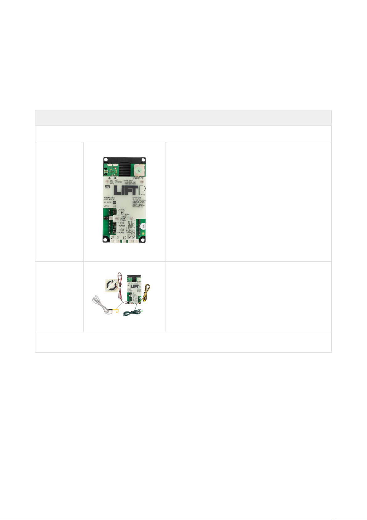
2N® LiftIP 2.0is an alarm lift communicator providing full-duplex audio transmission via the
VoIP technology directly from the lift cabin. A microphone and a speaker are built-in behind the
lift panel for bidirectional communication. 2N®LiftIP 2.0 is designed for sites where a LAN is
available and connected via an RJ-45 connector. 2N®LiftIP 2.0 can be fed either from a 10–30 V
DC / 0.5 A external supply or directly from the LAN if equipped with PoE 802.3af supporting
elements.From2N®LiftIP 2.0 you can only make calls to pre-programmed numbers. Thanks to
IP connectivity, 2N®LiftIP 2.0 can be constantly monitored, remotely configured and state
detected. The advantage is the connection option for an almost unlimited count of
communication units.
Advantages of Use:
Basic announcement set playing
Optimum acoustic properties
Configuration via device web interface
Adjustable speaker volume via audio unit buttons (during a call)
Recording of up to 8-minute long announcements (10 user messages)
Check call function once in 3 days (programmable)
Function indication – two LEDs meeting the applicable lift regulations
Automatic redialing of up to four numbers
Protection against unintentional/useless startup (CANCEL)
Call control from control center
No additional power supply requirement if PoE is used
•
Caution
This product, its installation and configuration are not intended for persons with
physical, sensory or mental disabilities or persons with limited experience and
skills unless expert supervision or relevant instructions are provided to them by a
person responsible for their safety.