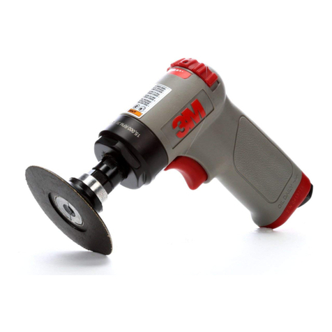
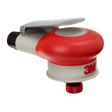
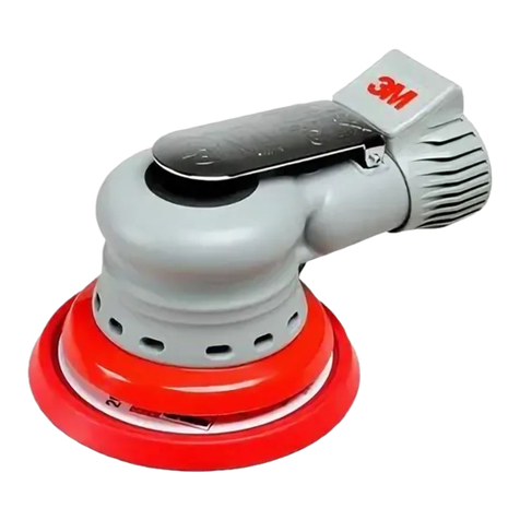
3M Buffer 8125 User manual

1
3M
Buffer 8125
Owner’s Manual
A table of contents:
A. SAFETY INFORMATION 1
B. OPERATING INSTRUCTION 4
C. SPARE PARTS INFORMATION (exploded view) 5
D. DISASSEMBLY METHOD 7
E. ASSEMBLY METHOD 10
F. GUIDELINE FOR PARTS EXCHANGE 11
G. PARTS DEPO AND REPAIR SERVICE 12
Appendix. – TROUBLESHOOTING CHART
A. SAFETY INFORMATION
Please read, understand, and follow all safety information contained in these instructions prior to the use of this tool.
Retain these instructions for future reference.
Intended Use:
This tool is designed as a buffing solution for repairing automobile bodies and parts, clear coat painting on metal, fiber
reinforced plastic (RFP) and wood. It should not be operated in water or in an excessive wet application.
Explanation of Signal Word Consequences
Indicates a potentially hazardous situation which, if not avoided, may result in death or serious injury
and/or property damage.
Indicates a potentially hazardous situation which, if not avoided, may result in minor or moderate
injury and/or property damage.
WARNING:
CAUTION:

2
To reduce the risks associated with excessive pneumatic pressure, noise, vibration, eye/skin irritation, and tool breakage during
the use of this product:
•Readandfollowthesafetyinformationcontainedintheseinstructionspriortotheuseofthistool.Retaintheseinstructionsforfuture
reference.
•Alwayswearprotectionforeyes*andearswhileoperatingthisproduct.FollowANSIZ87.1orlocal/nationalstandardsforeyewearand
other personal protective equipment requirements.
•Neverexceedmaximuminputpressureof90PSI(6.2bar).
•Neverpointthistoolinthedirectionofyourbodyorthatofanotherperson.
•Ifyounoticeanyabnormalnoiseorvibrationwhenoperatingtheproduct,immediatelydiscontinueitsuseandreturntothemanufacturer
for service or repair. Refer to warranty instructions.
•Discontinueuseofthetoolifabnormalhand/wristdiscomfortisexperienced.Ifdiscomfortcontinuesseekmedicalattention.
•UsedustcaptureorlocalexhaustasstatedintheMSDS.
•UsecareinfasteningHookit™DiscBackupPadtoensurethatitissecurelyattachedtothetoolbeforeuse.
•Makesurethetoolisdisconnectedfromtheairsourcebeforecleaning,inspecting,servicingorchanginganyparts.
WARNING
•Toreducetheriskofskinabrasion,cutsorburns,donottouchrotatingpartsduringoperationforanyreason.
CAUTION
•Improperusecancausethetooltobreakapartandmaycauseinjurytooperatorsandbystanders.
•Neverfreespinthetoolorallowittobestartedunintentionally.
•Neveroperatethetoolwithoutallguardsorsafetyfeaturesinplaceandinproperworkingorder.
•Inspectbackuppadandreplaceifunusualwearisnoticed.
•Replacebackuppadatnormalintervalsaccordingtoinstructions.
CAUTION
Motor
RPM
Orbit Dia. Air Flow Air
Pressure
Weight Pad Size Noise Vibration Length Height
10,500 0.472 in
(12 mm)
380LPM
(13.4 SCFM)
90PSI
(6.2bar)
2.09lbs
(0.95kg)
2.83in
(72 mm)
80dBA 1.34–1.46
m/s2
91/8in
(232 mm)
35/8in
(93mm)
*For information on eye and face protection, see ANSI Standard Z87.1,
“Practice for Occupational and Educational Eye and Face Protection”.
Available from American National Standards Institute, Inc., 1430 Broadway,
New York, NY 10018. +1 (212) 642-4900.

3
HOW TO HANDLE
•Checkforloosescrewsandmissingpartsbeforeoperation.
•Connectairhosesaftercleaningallappropriatettingstoreducecontaminationfromforeignobjects,dust,sand,etc.
•Duringinspectionofeachpartmakesuretodetachairhoses.
•Whenconnectingairhoseswithanairtool,donotsqueezethetrigger.
•Donotthrowthetool.
•Donotdragthetoolwhileholdingtheairhose.
•Donotusethetoolinanon-recommendedapplication.
•Operationwithoutlubricationwillcauserapidwearonthemotorandcanleadtorotationfailure.
•Priortostoring,lubricatethetoolatalowspeedtospreadoilinsidethemotor.
•Selectadryandsafeplaceforstorage.
•Frequentcleaningofairconnectionswillreducecontaminationofthemotor.
•Abnormalnoiseorvibrationduringoperationindicatesanimmediateneedfortoolrepair.
•Ifrepairisnecessarynotifysalesofceorrepaircenterfromwhereyoupurchasedthistoolregardinginspectionandrepair.
•Useonlyrecommendedreplacementparts.
PRIOR TO OPERATION
•Keeptheworkareaclean,orderlyandfreeofobstacles.
•Inspectforlooseparts(toolandattachment)priortooperation.
•Conrmthatairpressuredoesnotexceed90PSI/6.2bar.
•Whenconnectingtoanairhoseensureasecureconnectionthatwillnotloosenduringoperation.
•Centerthebufngpadonthebackuppad.
•Pressthebufngpadsecurelyintoplace.
START AND STOP
•Placethetoolincontactwiththeworkpiece.
•Startthetoolbypressingthelever/triggerlightly.
•Keepthetoolatwhileincontactwiththeworksurface.
•Slowthetooldownbeforeremovingfromtheworkpiece.
•Detachairhosewhenthetoolisnotinuse.
•Detachthetoolfromtheairsourcewhentransporting.
DURING OPERATION
•Speedcanbeadjustedfromlowtohighwiththespeedcontrollerknob.
•Donotapplyexcessiveforcetothetool.Excessiveforcecanleadtoinefcienttoolperformanceanddecreasedtoollife.
B. OPERATING INSTRUCTIONS
PRIOR TO OPERATION
•Makesuretheworkplaceisneatandisinappropriatecondition.
•Checkforlooseparts(pad,etc.).
•Makesuretheairpressureisappropriatelessthan90PSI(6.2bar).
•Whenacouplerorextensionisused,besureitistightsothatitwillnotcomeloosebecauseofvibration,etc.
START OF OPERATION
•Thetoolstartswhentheleverispressed.Itstopswhentheleverisreleased.Whenyouwork,besuretooperatetheleverafterthebufng
padcontactstheworksurface.

4
PRIOR TO OPERATION AND AFTER OPERATION
•Besuretooilthetoolmotorthroughtheairsupplyopening.Afteroiling,runthetoolatlowspeed.
•Whennotinproduction,removeairhoseandstoreinsafe,dryplace.

5
12
3
4
5
6
7
8
10
11
12
13
14
15
16-3
16-416-2
16-1
16-3
17
18
20
28
27
26
25
24
23
21
22 29
31
30
32
33
19
9
Parts Page

6
C. SPARE PARTS INFORMATION - continued
ITEM No. PART No. DESCRIPTION QTY
1 410320 Spring pin ( 3” x 20”) 1
2 22975A Valvelever 1
3 OV12 Snapring(OV-12) 1
4 20820 Valvepinsleeve 1
5 KS07 Oring(KS-7) 1
6 KS02 Oring(KS-2) 1
7 20823 Valve 1
8 25814 Valvespring 1
9 229013A Body 1
10 22952 Silencer 2
11 22953 Silencercap 1
12 130512 Screw (M5 x 12”) 1
13 3805 Washer(M5) 1
14 6000ZZ Ballbering(6000ZZ) 1
15 207083 U-baringcase 1
16 216031A Cylinderset 1set
16-1 216031 Cylinderset 1
16-2 KS05 O-ring(KS-5) 1
16-3 410308 Springpin(3”x8”) 2
16-4 410304 Springpin(3”x4”) 1
17 22621 Rotor 1
18 22622 Vane 8
19 22342 L-bearingcase 1
20 6300ZZ Ballbearing(6300ZZ) 1
21 22340 Shaft with head 1
22 510313 H/Rkey(13”x3”) 1
23 20913 Retainerbolt 1
24 6001DD Ballbearing(6001DD) 2
25 22309 18feltring 1
26 22308 Dustseal 1
27 22341 Pad retainer 1
28 OV28 Snapring(OV-28) 1
29 22907 Bodygasket 1
30 22951 Basering 1
31 22908 Dustpacking 1
32 150412 Screw (M4 x 12) 4
33 * 3”pad 1
* 3M™ Disc Pad 00-51111-55764-8
Special Tools for repair operation
ITEM No. PART No. DESCRIPTION QTY
1 ST005 6200bearingpunch 1
2 ST007 3 mm pin punch 1
3 ST008 945Ashaftbearingpuller 1
4 ST024 Bearing puller stand 1
5 ST502 Snap ring pliers 1
7
D. DISASSEMBLY METHOD
Remove the air hose before disassembling the tool. Disassembly while the air hose is still attached is very dangerous.
CAUTION
1. Remove pad holder.
Use the attached spanner to remove the pad. Secure the pad retainer (27) and rotate the pad (33)
inthecounterclockwisedirection.
2. Removing the Base Ring
Removefourscrews(32)andremovethebasering(30).Removethebodygasket(29).
3. Disassembly of the Motor
Remove the motor assembly. Remove the screw (12) from the up-
per end of the motor assembly.
Remove the ball bearing as well as
theU-bearingcase(14&15).

8
Remove the ball bearing (14)
using a special puller.
Removethecylinderset(16). Removethevanes(18).
Remove the ball bearing (14)
using a special puller.
RemovetheH/Rkey(22). TheL-bearingcaseandtheballbearing
(19&20)areremovedusingaplastichammer
so that the shaft (21) will not be damaged.
Theballbearing(20)isremovedfromtheL-bearingcase(19)usingaspecialpuller.
Removethesnapring(28)from
the shaft assembly.
Remove the pad retainer assembly
using a special tool.
Clamp the pad retainer (27) in a vise
and remove the retainer bolt.

9
Remove the ball bearing (24)
using a special tool.
Removethedustseal(26)andthe
18Diafeltring(25).
4. Disassembly of the Valve
Removethedustseal(26)and
f18diameterfeltring(25).
Using a snap ring tool, remove the
snap ring (3).
Remove the valve pin sleeve and the
O-ringKS-7(4&5)togetherwiththe
O-ringKS-2andthevalve(6&7).
Be careful not to lose the valve spring.
RemovetheO-ringKS-2andthe
valve(6&7)fromthevalvepin
sleeveandtheO-ringKS-7(4&5).
RemovetheO-ringKS-7(5)outfrom
the valve pin sleeve (4).
RemovetheO-ringKS-2(6)from
the valve (7).

10
ST502
ST005 ST008
ST024
ST007
1) ST005 6200bearingpunch
2) ST007 3 mm pin punch
3) ST008 945Ashaftbearingpuller
4) ST024 Bearing puller stand
5) ST502 Snap ring pliers
5. Special tools for the repair operation (to help the disassembly)
E. ASSEMBLY METHOD
•Beforeassembly,inspecteachpartforwearordamage.
•Useonlyrecommendedspareparts.
•Applyoillightlyoneachpart.
•ExchangedamagedOrings.DonotomittheOrings.
•Applygrease(generalpurposegrease).
•Assemblethepartscarefullyinthereverseorderfromthedisassembly.
•Assemblethemotor,payingspecialattentiontotherequiredupperandlowerclearance.
•Whenassemblyisnished,checkforloosescrews,etc.
•Pourafewdropsofairtooloilintotheairinletpart,andrunataslowspeed.
•Checkthatitrotatesfreely.

11
F. GUIDELINE FOR PARTS REPLACMENT
PARTS No. CODE ITEM WHEN TO REPLACE
1 410320 Spring pin ( 3” x 20”) When the hinge is worn excessively
2 22975A Valvelever Whenthepinretainerisworn
3 OV12 Snapring(OV-12)
4 20820 Valvepinsleeve Whentheslideisworn
5 KS07 Oring(KS-7) Whenitisdamagedandcausesaleak
6 KS02 Oring(KS-2) Whenitisdamagedandcausesaleak
7 20823 Valve Whenitleaks
8 25814 Valvespring Whenitisbentorjustdoesn’twork
9 229013A Body
10 22952 Silencer
11 22953 Silencercap
12 130512 Screw (M5 x 12)
13 3805 Washer(M5)
14 6000ZZ Ballbering(6000ZZ) Whenithasexcessiveplayorislocked
15 207083 U-baringcase Whenthebearingretainerisdamaged
16 216031A Cylinderset
16-1 216031 Cylinder Whenthesealingsurfaceisdamagedorworn
16-2 KS05 O-ring(KS-5) Whenitisdamagedandcausesaleak
16-3 410308 Springpin(3”x8”)
16-4 410304 Springpin(3”x4”)
17 22621 Rotor Whenitisworn,causingleaksorexcessivevibration
18 22622 Vane Whenthewidthbecomes-0.5lessthantheoriginalsize(0.9);
whenthelengthbecomes-0.25lessthantheoriginalsize(22)
19 22342 L-bearingcase Whenthebearingislooseorotherdamageisfound
20 6300ZZ Ballbearing(6300ZZ) Whenithasexcessiveplayorislocked
21 22340 Shaft with head When the joint with the rotor is worn and vibration is excessive
22 510313 H/Rkey(13”x3”) Whenvibrationisexcessive
23 20913 Retainerbolt
24 6001DD Ballbearing(6001DD) Whenishasexcessiveplayorislocked
25 22309 18feltring Changeeverytimethetoolisserviced
26 22308 Dustseal
27 22341 Pad retainer When the bearing surface is worn or
the screw holes are stripped
28 OV28 Snapring(OV-28)
29 22907 Bodygasket Replacewhenthetoolisserviced
30 22951 Basering WhendamagehasoccurredtotheOD
31 22908 Dustpacking
32 150412 Screw (M4 x 12)
33 * 3”pad Whenbent,whenvibrationisexcessiveor
when the OD is badly damaged
* 3M™ Disc Pad 00-51111-55764-8

12
G. PARTS DEPO AND REPAIR SERVICE
g. PARTS DEPO AND REPAIR SERVICE
Repair services after Warranty period & Parts supply contact
Tool Warehouse Inc.
Contact: Jeff Houk
3410 East 42nd Street,
Minneapolis, MN 55406-3333
Phone: 1-612-722-4260 Fax: 1-612-722-3415
e-mail: sales@ToolWarehouseInc.com
3M Industrial Business Quality Direct / abrasives
Phone: 1-800-362-3550 (USA only)
3M Industrial Business Customer Response Center
900 Bush Avenue, Building 21-1W-10
St. Paul, MN 55106
Phone: 1-866-279-1235
www.3M.com/abrasives © 3M 2007
12
©3M2008

13

14
Product Use: All statements, technical information and recommendations contained in this document are based up on
testsorexperiencethat3Mbelievesarereliable.However,manyfactorsbeyond3M’scontrolcanaffecttheuseand
performance of a 3M product in a particular application, including the conditions under which the 3M
product is used and the time and environmental conditions in which the product is expected to perform. Since these
factorsareuniquelywithintheuser’sknowledgeandcontrol,itisessentialthattheuserevaluatethe3Mproductto
determinewhetheritistforaparticularpurposeandsuitablefortheuser’smethodofapplication.
Warranty and Limited Remedy:3Mwarrantsthistoolagainstdefectsinworkmanshipandmaterialsundernormal
operatingconditionsforOne(1)yearfromthedateofpurchase.3MMAKESNOOTHERWARRANTIES,EXPRESSOR
IMPLIED, INCLUDING, BUT NOT LIMITED TO, ANY IMPLIED WARRANTY OF MERCHANTABILITY OR FITNESS FOR A
PARTICULAR PURPOSE OR ANY IMPLIED WARRANTY ARISING OUT OF A COURSE OF DEALING, CUSTOM OR USAGE OF
TRADE.Userisresponsiblefordeterminingwhetherthe3Mtoolistforaparticularpurposeandsuitableforuser’s
application. User must operate the tool in accordance with all applicable operating instructions, safety precautions, and
other procedures stated in the operating manual to be entitled to warranty coverage. 3M shall have no obligation to repair
or replace any tool or part that fails due to normal wear, inadequate or improper maintenance, inadequate cleaning,
non-lubrication,improperoperatingenvironment,improperutilities,operatorerrorormisuse,alterationormodication,
mishandling,lackofreasonablecare,orduetoanyaccidentalcause.Ifatooloranypartthereofisdefectivewithinthis
warrantyperiod,yourexclusiveremedyand3M’ssoleobligationwillbe,at3M’soption,torepairorreplacethetoolor
refund the purchase price.
Limitation of Liability: Except where prohibited by law, 3M and seller will not be liable for any loss or damage arising
from the 3M product, whether direct, indirect, special, incidental or consequential, regardless of the legal theory
asserted, including warranty, contract, negligence or strict liability.
Submitting a Warranty Claim: Contact your dealer when submitting a warranty claim in accordance with the restrictions
listedabove.Pleasenotethatallwarrantyclaimsaresubjecttomanufacturer’sapproval.Besuretokeepyour
sales receipt in a safe place. This must be submitted when filing a warranty claim, within One (1) year from the date of
purchase.
Product Repair after Warranty Has Expired
3M does not offer repair service for product out of warranty.
3M
Abrasive Systems Division
3MCenter,Building223-6N-02
St.Paul,MN55144-1000
www.3M.com/abrasives
©3M2008
3MandHookitaretrademarksof3MCompany
34-8701-9414-8

15
Contact: Michelle Dumas
Creator:deZinnia
Spec#34-8701-9414-8
Structure: NA
Inks:Black
Date:09/23/08
This artwork has been created as requested by 3M. 3M is responsible for the artwork
AS APPROVED and assumes full responsibility for its correctness.
Other 3M Sander manuals

3M
3M 28825 User manual

3M
3M 28547 User manual

3M
3M 28342 User manual

3M
3M 28337 User manual

3M
3M 20244 User manual

3M
3M 33573 Operator's manual

3M
3M File Belt Sander User manual

3M
3M Perfect-It 3MROP15 User manual

3M
3M ELECTRIC RANDOM ORBITAL SANDER User manual

3M
3M RANDOM ORBITAL SANDERS Operating instructions