3M 28341 User manual

1
Disc Sander - INSTRUCTIONS MANUAL
2 in (50 mm) 12,000 RPM .33 HP, 2 in (50 mm) 20,000 RPM .33 HP,
2 in (50 mm) 12,000 RPM .5 HP, 2 in (50 mm) 20,000 RPM .5 HP,
3 in (76 mm) 15,000 RPM 1 HP
Please read, understand and follow all safety information contained in these instructions prior to the use of this tool.
Retain these instructions for future reference.
This pneumatic tool is intended for use in industrial locations, and used only by skilled, trained professionals in accordance with the instructions in this
manual. This pneumatic tool is designed to be used with the sander adaptor, disc pad, and appropriate abrasive for sanding metals, wood, stone, plastics and
other materials. Additionally, when used with the collet chuck* it may also function as a Die Grinder. It should only be used for such sanding and die grinding
applications and within its marked capacity and ratings. Only accessories specifically recommended by 3M should be used with this tool. Use in any other manner
or with other accessories could lead to unsafe operating conditions.
Do not operate tool in water or in an excessively wet application.
Do not use disc pads that have a Max RPM less than the tool Max RPM rating.
*In the drawings on the Parts Pages, Figures 2, 3 and 4 comprise the Collet Chuck.
Explanation of Signal Word Consequences
WWARNING Indicates a potentially hazardous situation which, if not avoided, may result in death or serious injury and/or property damage.
WCAUTION Indicates a potentially hazardous situation which, if not avoided, may result in minor or moderate injury and/or property damage.
To reduce the risks associated with impact from abrasive product, disc pad, or tool breakup, sharp edges, hazardous pressure, rupture, vibration
and noise:
•Read,understandandfollowthesafetyinformationcontainedintheseinstructionspriortotheuseofthistool.Retaintheseinstructionsforfuturereference.
•Onlypersonnelwhoareproperlytrainedshouldbeallowedtoservicethistool.
•Practicesafetyrequirements.Workalert,haveproperattire,anddonotoperatetoolundertheinuenceofalcoholordrugs.
•Operatorsandotherpersonnelmustalwayswearprotectionforeyes,ears,andrespiratoryprotectionwhenintheworkareaorwhileoperatingthis
product. Follow your employer’s safety policy for PPE’s and/or ANSI Z87.1 or local/national standards for eyewear and other personal protective equipment
requirements.
•Wearprotectiveapparel,takingintoconsiderationthetypeofworkbeingdone.
•Neverexceedmarkedmaximuminputpressure(90psi/.62Mpa/6.2Bars).
•Propereyeprotectionmustbewornatalltimes.
•Toolshallnotbeoperatedinthepresenceofbystanders.
WWARNING
Important Safety Information
Intended Use
3
Original Instructions
MSDS
WWARNING!
Read the Material Safety
DataSheets(MSDS)
before using any materials.
Contact the suppliers of the
workpiece materials and
abrasive materials for copies
of the MSDS if one is not
readily available.
Exposure to DUST generated from
workpiece and/or abrasive materials
can result in lung damage and/or other
physical injury.
Use dust capture or local exhaust as
stated in the MSDS. Wear government-
approved respiratory protection and eye
and skin protection.
Failure to follow this warning can
result in serious lung damage and/or
physical injury.

1 2
•Ifyounoticeanyabnormalnoiseorvibrationwhenoperatingtheproduct,immediatelydiscontinueitsuseandinspectforwornordamagedcomponents.
Correct or replace the suspect component. If abnormal noise or vibration still exists, return the tool to 3M for repair or replacement. Refer to warranty
instructions.
•Neveroperatethistoolwithoutallsafetyfeaturesinplaceandinproperworkingorder.
•Neverover-rideordisablethesafetyfeaturesofthestart-stopcontrolsuchthatitisintheonposition.
•Makesurethetoolisdisconnectedfromitsairsourcebeforeservicing,inspecting,maintaining,cleaning,andbeforechangingabrasiveproduct.
•Priortouse,inspectabrasiveproduct,discpad,andotheraccessoriesforpossibledamage.Ifdamaged,replacewithnewabrasiveproductandaccessories
available from 3M.
•Onlyuseabrasivediscpadsandotheraccessoriessuppliedby3M.
•Useonlywithmountinghardwarerecommendedby3M;checkwith3Mformountinghardwarerequirements.
•Alwaysensurethatshaftdiametersmatchinternaldiametersofthecolletinserts.
•Maximumoperatingspeedofabrasiveproductsoraccessoriesmustbereducedwhenevertheexposedlengthofshaft(overhang)islongerthan
corresponding 3M approved products.
•Alwaysensurethataminimumof10mmshaftgrippinglengthisobserved.
•Neverinstallanduserouterbitsorcutting-offwheelsinadiegrindertool(whichisunguarded).
•Useonlywithabrasiveproductsnotrequiringguardsaccordingtolocal,stateandfederalregulations.
•Neverallowthistooltobeusedbychildrenorotheruntrainedpeople.
•Donotleaveanunattendedtoolconnectedtoairsource.
To reduce the risks associated with vibration:
•Ifanyphysicalhand/wristdiscomfortisexperienced,workshouldbestoppedpromptlytoseekmedicalattention.Hand,wristandarminjurymayresultfrom
repetitive work, motion and overexposure to vibration.
To reduce the risks associated with loud noise:
•Alwayswearprotectionforeyes,ears,andrespiratoryprotectionwhileoperatingthisproduct.Followyouremployer’ssafetypolicyforPPE’sand/orANSI
Z87.1 or local/national standards for eyewear and other personal protective equipment requirements.
To reduce the risks associated with fire or explosion:
•Donotoperatethetoolinexplosiveatmospheres,suchasinthepresenceofammableliquids,gases,ordust.Theabrasivesareabletocreatesparkswhen
workingmaterial,resultingintheignitionoftheammabledustorfumes.
•RefertoMSDSofmaterialbeingworkedastopotentialforcreatingreorexplosionhazard.
To reduce the risks associated with hazardous dust ingestion or eye/skin exposure:
•Useappropriaterespiratoryandskinprotection,orlocalexhaustasstatedintheMSDSofthematerialbeingworkedon.
To reduce the risks associated with hazardous voltage:
•Donotallowthistooltocomeintocontactwithelectricalpowersourcesasthetoolisnotinsulatedagainstelectricalshock.
WCAUTION
To reduce the risks associated with skin abrasion, burns, cuts, or entrapment:
•Keephands,hair,andclothingawayfromtherotatingpartofthetool.
•Wearsuitableprotectivegloveswhileoperatingtool.
•Donottouchtherotatingpartsduringoperationforanyreason.
•Donotforcetooloruseexcessiveforcewhenusingtool.
To reduce the risks associated with whipping or hazardous pressure-rupture:
•Ensuresupplyhoseisoilresistantandisproperlyratedforrequiredworkingpressure.
•Donotusetoolswithlooseordamagedairhosesorttings.
•Beawarethatincorrectlyinstalledhosesandttingsmightunexpectedlycomelooseatanytimeandcreateawhipping/impacthazard.
To reduce the risks associated with fly off of abrasive product parts:
•Usecareinattachingabrasiveproduct,discpad,andmountinghardware;followingtheinstructionstoensurethattheyaresecurelyattachedtothetool
before use or free-spinning.
•Neverpointthisproductinthedirectionofyourselforanotherperson,orstarttoolunintentionally.
•Neverover-tightenaccessoryfasteners.
WWARNING

3
Parts Page
PARTS LIST FOR PN 28341 & 28342, 20,000 RPM and PN 28328 & 28343,
12,000 PRM, 2 in, .33 HP Disc Sander
Fig. 3M PN Description
1 06582 SanderAdapter
2 06583 ColletBody
3 06528 Collet(1/4in)
06529 Collet(1/8in)
06530 Collet(3/16in)
06540 Collet(3mm)
06541 Collet(6mm)
4 06516 ColletNut
5 30386 RetainingRing(20KRPM)
30387 RetainingRing(12KRPM)
6 06581 OutputShaft(20KRPM)
30385 OutputShaft(12KRPM)
7 30368 Bearing(20KRPM)
30391 Bearing(12KRPM)
8 06645 BevelGearSet(20KRPM)
30434 BevelGearSet(12KRPM)
9 06505 NeedleBearing
10 30384 97°AngleHeadAssembly(20KRPM)
(IncludesFigures9,11)
30383 97°AngleHeadAssembly(12KRPM)
(IncludesFigures9,11)
11 06523 GreaseFitting
12 30411 ClampNut
13 30399 RetainingRing
14 30416 AngleHeadSpacer
Fig. 3M PN Description
15 06611 BallBearing
16 30413 FrontEndPlate
17 06624 FrontEndPlateSpacer(Natural)
18 30417 ThreadedRotor
19 30435 VaneSet
20 30415 Cylinder
21 30414 RearEndPlate
22 06612 BallBearing
23 30403 O-Ring
24 30409 Housing
25 30405 O-Ring
26 30406 ValvePin
27 06614 CompressionRing
28 30401 O-Ring
29 30407 Regulator
30 06613 CompressionSpring
31 06622 SteelBall
32 30394 RegulatorPin
33 28573 Cover
34 30412 PaddleAssembly
35 30395 Pin
36 30410 Mufer
37 30382 RotatableExhaust
38 30398 InletBushing
39 06586 Wrench(2)
USE 3M TL62 THREADLOCKER
TO 90-130 IN-LB
LUBRICATE ANGLE HEAD
FUCHS RENOLIT
A X S2 OR EQUAL
WITH 1.0-1.5 OZ OF
INSTALL RETAINING
RING WITH BEVEL
FACING OUT
USE 3M TL62
THREADLOCKER
TO 10-15 FT-LB
15
16 17
18
19
20
21 22 23
39
24
25
26
27
28
29
30
31
32
33
34 35
36
37
38
2
3
4
5
6
7
8
9
10
11
12
13
14
1
8
USE 3M TL62 THREADLOCKER
TO 50 IN-LB

3 4
Parts Page
PARTS LIST FOR PN 20231 & 25124, 20,000 RPM and 28329 & 28344,
12,000 RPM, 2 in, .5 HP Disc Sander
Fig. 3M PN Description
1 06582 SanderAdapter
2 06583 ColletBody
3 06529 Collet(1/8in)
06530 Collet(3/16in)
06528 Collet(1/4in)
06540 Collet(3mm)
06541 Collet(6mm)
4 06516 ColletNut
5 06633 LockNut(20KRPM)
30386 RetainingRing(12KRPM)
6 06581 OutputShaft(20KRPM)
30385 OutputShaft(12KRPM)
7 06611 BallBearing(20KRPM)
30368 BallBearing(12KRPM)
8 06645 BevelGearSet(20KRPM)
30434 BevelGearSet(12KRPM)
9 06505 NeedleBearing
10 30438 97°AngleHeadAssembly(20KRPM)
(IncludesFigures9,11)
06580 97°AngleHeadAssembly(12KRPM)
(IncludesFigures9,11)
11 06523 GreaseFitting
12 06636 ClampNut
13 06619 RetainingRing
14 06611 BallBearing
Fig. 3M PN Description
15 06629 FrontEndPlate
16 06621 O-Ring
17 30418 FrontEndPlateSpacer(Black)
18 06634 Rotor
19 06647 Vane,Setof5
20 06631 CylinderLiner
21 06630 RearEndPlate
22 06612 BallBearing
23 06625 Housing
24 06626 TriggerValveStem
25 30400 O-Ring
26 06614 CompressionSpring
27 06620 O-Ring
28 06627 AirRegulator
29 06613 CompressionSpring
30 06622 SteelBall
31 06616 Pin
32 06599 HousingCover,.5HP
33 06635 PaddleAssembly
34 06617 RollPin
35 06632 MuferMaterial
36 06615 DiscSpring
37 06628 ExhaustDeector
38 06618 InletBushing
39 06586 7/16inx11/16inWrench(2)*
23
24
25
26
27
28
29
30
31
32
34
33
35 36
38
39
LUBRICATE
ANGLE HEAD
WITH 1.0-1.5 OZ OF
FUCHS RENOLIT
A X S2 OR EQUAL
17
18
19
20
21 22
14
15 16
6
11
1
5
7
8
9
10
2
3
4
8
12 13
USE 3M TL62 THREADLOCKER
TO 90-130 IN-LB
USE 3M TL62 THREADLOCKER
TO 10-15 FT-LB
USE 3M TL62 THREADLOCKER
TO 50 IN-LB
USE 3M TL62
THREADLOCKER
TO 50 IN-LB
LEFT HAND THREAD
37

5
PARTS LIST FOR PN 20232 & 25125, 15,000 RPM 3 in, 1 HP Disc Sander
Parts Page
Fig. 3M PN Description
1 06582 SanderAdapter
2 06583 ColletBody
3 06529 Collet(1/8in)
06530 Collet(3/16in)
06528 Collet(1/4in)
06540 Collet(3mm)
06541 Collet(6mm)
4 06516 ColletNut
5 06578 BearingRetainer
6 06591 OutputShaft
7 06507 BallBearing
8 06646 SpiralBevelGearSet
9 06505 NeedleBearing
10 06637 AngleHeadAssembly
(IncludesFigures9&11)
11 06523 GreaseFitting
12 06653 AngleHeadClampNut
13 06655 LockRing
14 06520 Pin,1/8inx1/4in
15 06609 O-Ring
16 06510 BallBearing3/8inx7/8inx9/32in
17 06639 FrontEndPlate
18 06562 Rotor
19 06643 Vane,Setof5
20 06563 Cylinder
Fig. 3M PN Description
21 06560 RearEndPlate
22 06527 WaveWasher
.440inx.618inx.008in
23 06508 BallBearing
24 06567 Washer.251inx.468inx.063in
25 06568 Screw#8-32x3/8inButHdCap
26 06638 Housing
27 06558 TorrPin,3/16inx7/8in
28 06543 O-Ring
29 06511 O-Ring
30 06556 Regulator
31 06501 Screw,6-32x3/4inSetSocHex
32 06598 HousingCover
33 06642 Lever
34 06559 GroovePin,1/8inx7/8inTypeE
35 06566 WarningLabel
36 06557 Mufer
37 06552 ThrottleValveSeat
38 06553 ThrottleValve
39 06554 TaperSpring
40 06555 Screen
41 06608 O-Ring,1/16inx5/8inx3/4in
42 06604 RotatableExhaustDeector
43 06605 InletBushing
44 06586 7/16inx11/16inWrench(2)*
36 37 38 39 40 41
42 43
44
16
17 18
19
20
21 22 23 24 25
2
3
4
32
33
34 35
26
27
28
29
30
31
14
13
15
12
5
9
10
11
7
8
6
1
8
LUBRICATE
ANGLE HEAD WITH
1.0-1.5 OZ OF
FUCHS RENOLIT
A X S2 OR EQUAL
INSTALL RETAINING RING
WITH BEVEL FACING OUT USE 3M TL62
THREADLOCKER
USE 3M TL62 THREADLOCKER
TO 20-25 FT-LB
USE 3M TL62 THREADLOCKER
TO 15-20 FT-LB
LEFT HAND
THREAD
USE 3M TL62
THREADLOCKER
TO 90-130 IN-LB

5 6
* Declarednoiselevels;measurementscarriedoutinaccordancewithstandardENISO15744:2002.
**DeclaredvibrationlevelsinaccordancewithEN12096;measurementscarriedoutinaccordancewithstandardENISO8662-8:1997fordiscsanderapplication
andENISO8662-13:1997fordiegrinderapplication.
IMPORTANTNOTE:Thenoiseandvibrationvaluesstatedinthetablearefromlaboratorytestinginconformitywithstatedcodesandstandardsandarenot
sufficient risk evaluation for all exposure scenarios. The actual exposure values and amount of risk or harm experienced to an individual is unique to each
situation and depends upon the surrounding environment, the way in which the individual works, the particular material being worked, work station design, as
well as upon the exposure time and the physical condition of the user. 3M cannot be held responsible for the consequences of using declared values instead of
actual exposure values for any individual risk assessment.
PRIORTOTHEOPERATION
Thetoolisintendedtobeoperatedasahandheldtool.Itisalwaysrecommendedthatwhileusingthetool,operatorsstandonasolidoor,inasecureposition
witharmgripandfooting.Beawarethatthesandercandevelopatorquereaction.Seethesection“SAFETYPRECAUTIONS”.
Useacleanlubricatedairsupplythatwillgiveameasuredairpressureatthetoolof6.2bar(90psig)whenthetoolisrunningwiththeleverfullydepressed.Itis
recommendedtouseanapproved10mm(3/8in)x8m(25ft)maximumlengthairline.ConnectthetooltotheairsupplyasshowninFigure1.Donotconnect
thetooltotheairlinesystemwithoutaneasilyaccessibleairshutoffvalve.Itisstronglyrecommendedthatanairlter,regulatorandlubricator(FRL)beused
as shown in Figure 1 as this will supply clean, lubricated air at the correct pressure to the tool. In any case appropriate air pressure regulators shall be used at
all times while operating this tool where the supply pressure exceeds the marked maximum of the tool. Details of such equipment can be obtained for your tool
distributor. If such equipment is not used, the tool should be manually lubricated. To manually lubricate the tool, disconnect the airline and put 2 to 3 drops of
suitablepneumaticmotorlubricatingoilsuchas3M™AirToolLubricantPN20451,FujiKosanFK-20orMobilALMO525intothehoseend(inlet)ofthetool.
Reconnect tool to the air supply and run tool slowly for a few seconds to allow air to circulate the oil. If the tool is used frequently, lubricate it on a daily basis or
lubricateitifthetoolstartstosloworlosepower.Itisrecommendedthattheairpressureatthetoolbe6.2bar(90psig)whilethetoolisrunningsothemaximum
RPMisnotexceeded.Thetoolcanberunatlowerpressuresbutshouldneverberunhigherthan6.2bar(90psig).Ifrunatlowerpressuretheperformanceofthe
tool is reduced.
Product Configuration / Specifications
Operating / Maintenance Instructions
Recommended Airline
Size - Minimum
10mm3/8in
Recommended Maximum HoseLength
8meters25feet
Air Pressure
MaximumWorkingPressure6.2bar90psig
Recommended Minimum N/A N/A
Lubricatetheangleheadevery6-8workinghourswithpremiumgreasewiththefollowingproperties:
- Highandlowtemperatureperformance
- Shear stable
- Anti-wear protection
- Lowviscositybaseuidforhighspeedapplication
- Verylowcoefcientoffriction
Fuchs Renolit AX S2 or equal is recommended. Grease gun and grease available from your grease supplier.
Model
Number Collet Pad
Type Pad
Part Speed
RPM Power
(hp) Product
Net
Wt kg
(lb)
Height
mm (in) *Noise
Level
dBA
Pressure
(Power)
** Vibration
Level
m/s2
(ft/s2)
**
Uncertainty
K
m/s2
** Vibration
Level
Configured
as
Grinder
m/s2(ft/s2)
**
Uncertainty
K
Configured
as
Grinder
m/s2
28341
28342 1/4 in
6mm
2 in
Roloc
Hard 88746 20,000 .33 0.49(1.09)
0.49(1.09) 63.5(2.5)
63.5(2.5) 80.5(92.1)
80.5(92.1) <2.5(<8.20)
<2.5(<8.20) NA
NA 4.32(14.21)
4.32(14.21) 0.261
0.261
28328
28343 1/4 in
6mm
2 in
Roloc
Hard 88746 12,000 .33 0.49(1.09)
0.49(1.09) 63.5(2.5)
63.5(2.5) 80.5(92.1)
80.5(92.1) <2.5(<8.20)
<2.5(<8.20) NA
NA 4.32(14.21)
4.32(14.21) 0.261
0.261
28329
28344 1/4 in
6mm
2 in
Roloc
Hard 88746 12,000 .5 0.58(1.28)
0.58(1.28) 69.9(2.75)
69.9(2.75) 89.3(100.9)
89.3(100.9) 6.56(21.6)
6.56(21.6) 2.624
2.624 7.41(24.4)
7.41(24.4) 2.964
2.964
20231
25124 1/4 in
6mm
2 in
Roloc
Hard 88746 20,000 .5 0.58(1.28)
0.58(1.28) 69.9(2.75)
69.9(2.75) 89.3(100.9)
89.3(100.9) 6.56(21.6)
6.56(21.6) 2.624
2.624 7.41(24.4)
7.41(24.4) 2.964
2.964
20232
25125 1/4 in
6mm
3 in
Roloc
Hard 45091 15,000 10.89(1.97)
0.89(1.97) 82.6(3.25)
82.6(3.25) 84.5(95.1)
84.5(95.1) 5.98(19.7)
5.98(19.7) 2.392
2.392 4.87(16.0)
4.87(16.0) 1.948
1.948

7
3M™ Roloc™ Disc Pads are mated for use on the 3M Sander. Constructed
from premium, industrial-quality materials and their durability and precise
construction are the ideal complement to the performance of the 3M Sander.
See Product Configuration/Specifications table for the correct replacement
pad for a particular model.
See3MASDAccessorycatalog61-5002-8098-9and61-5002-8097-1for
additional Accessories.
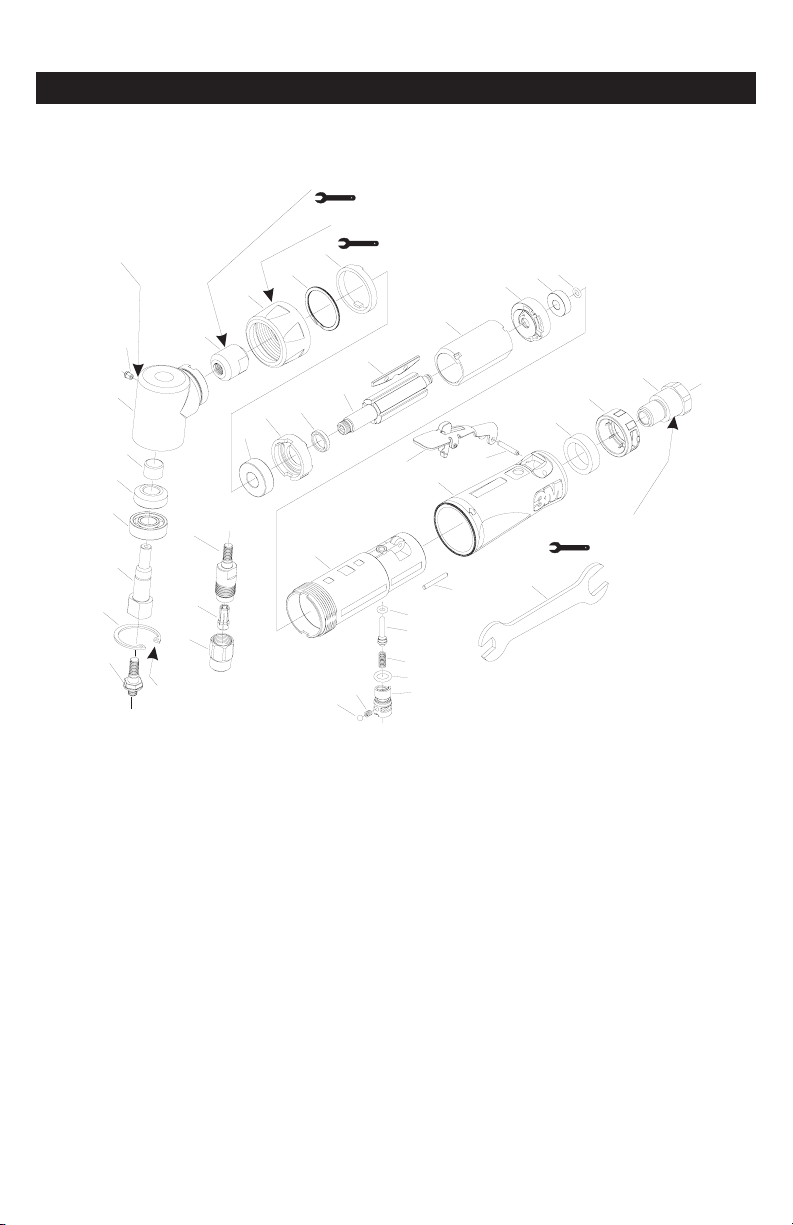
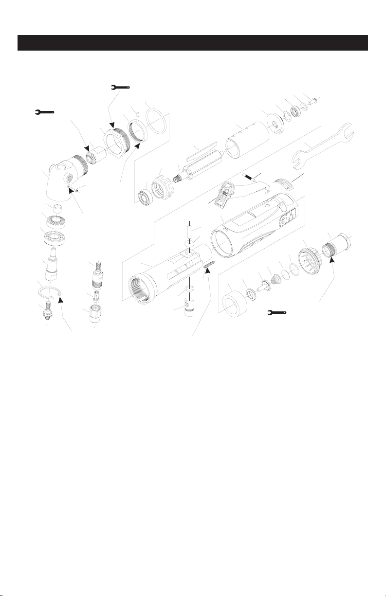
Removing the sander adaptor and installing
the collet chuck
1. Disconnect air line from tool.
2. Using the wrenches supplied with the tool, secure the output shaft with
oneofthewrenches.Loosenthesanderadaptorwiththeotherwrench.
3. Thread the collet chuck* supplied with the tool into the threaded hole
vacated by the sander adaptor.
4. Tighten the base of the collet chuck with the two wrenches.
5. Loosenthecollarofthechucktoallowtheappropriateshanktobe
inserted(¼in.colletinsertisusedfor¼in.shanks,6mmcolletinsertis
usedfor6mmshanks).
6. Insertshankcompletelyintothecolletandtightenwiththetwo
wrenches. Never tighten collet chuck without a shank. An inadequately
inserted shank could bend or break causing damage to the tool and
work piece and possible injury to the operator or bystanders.
Note:Duringtheabovesteps,ensurethatallhardwareandabrasive
products are mounted concentrically on the supporting accessory
*In the drawings on the Parts Pages, Figures 2, 3 and 4 comprise the Collet
Chuck.
1. Read all instructions before using this tool. All operators must be fully
trained in its use and aware of these safety rules.
2. The tool RPM should be checked on a regular basis to ensure proper
operating speed.
3. Make sure the tool is disconnected from the air supply. Attach the 3M™
Roloc™ Disc Pad to the sander adaptor using the wrenches supplied
with the tool. Select a suitable abrasive and secure it to the disc pad.
4. Always wear required safety equipment when using this tool.
5. Whensandingalwaysstartthetooljustpriortocontactingthework
piece.Stopairowtothetoolasitisremovedfromtheworkpiece.
6. Alwaysremovetheairsupplytothesanderbeforetting,adjustingor
removing the abrasive or disc pad.
7. Always adopt a firm footing and grip and be aware of torque reaction
developed by the sander.
8. Use only 3M approved spare parts.
9. Alwaysensurethematerialbeingworkedisrmlyxedtoavoid
movement.
10.Checkhoseandttingsregularlyforwear.Donotcarrythetoolbyits
hose;alwaysbecarefultopreventthetoolfrombeingstartedwhen
carrying the tool with the air supply connected.
11. Dust can be highly combustible.
12. If tool is serviced or rebuilt check to ensure that the maximum tool RPM
is not exceeded and that there is no excessive tool vibration.
13. Do not exceed maximum recommended air pressure. Use safety
equipment as recommended.
14. Prior to installing any sanding or polishing accessory, always check that
it’s marked maximum operating speed is equal or higher than the rated
speed of this tool.
15.Thetoolisnotelectricallyinsulated.Donotusewherethereisa
possibility of contact with live electricity, gas pipes, and/or water pipes.
16.Thistoolisnotprotectedagainsthazardsinherentingrindingand
cutting operations, which require a guard, and no such grinding and
cutting products should ever be attached.
17. Take care to avoid entanglement with the moving parts of the tool with
clothing, ties, hair, cleaning rags or loose hanging objects. If entangled,
stop air supply immediately to avoid contact with moving tool parts.
18.Keephandsclearofthespinningpadduringuse.
19.Ifthetoolappearstomalfunction,removefromuseimmediatelyand
arrange for service and repair.
20.Immediatelyreleasethestarthandleintheeventofanydisruption
ofpressure;donotattempttorestartuntilthedisruptionhasbeen
corrected.
21. Do not allow the tool to free spin without taking precautions to protect
anypersonsorobjectsfromdebrisfromrupturingabrasive&mounting
hardware.
22. When tool is not in use, store in a clean dry environment free of debris.
23.RecycleordisposeoftoolaccordingtoLocal,State,andFederal
regulations.
Safety Precautions
3M™ Roloc™ Disc Pads
Figure 1
Closed Loop Pipe System
Sloped in the direction of air flow
Drain Leg
Ball Valve
To Tool Station
Filter
Drain Valve
Regulator
Lubricator
Ball
Valve
Ball Valve Air Flow
Air Dryer
Air Compressor
and Tank
Air Hose
To Coupler
at or near Tool

7 8
Product Use: All statements, technical information and recommendations
contained in this document are based up on tests or experience that 3M
believesarereliable.However,manyfactorsbeyond3M’scontrolcan
affect the use and performance of a 3M product in a particular application,
including the conditions under which the 3M product is used and the time
and environmental conditions in which the product is expected to perform.
Since these factors are uniquely within the user’s knowledge and control, it
is essential that the user evaluate the 3M product to determine whether it is
fit for a particular purpose and suitable for the user’s method of application.
Warranty and Limited Remedy: 3M warrants this tool against defects
in workmanship and materials under normal operating conditions for one
(1)yearfromthedateofpurchase.3MMAKESNOOTHERWARRANTIES,
EXPRESSORIMPLIED,INCLUDING,BUTNOTLIMITEDTO,ANYIMPLIED
WARRANTYOFMERCHANTABILITYORFITNESSFORAPARTICULARPURPOSE
ORANYIMPLIEDWARRANTYARISINGOUTOFACOURSEOFDEALING,
CUSTOM OR USAGE OF TRADE. User is responsible for determining whether
the 3M tool is fit for a particular purpose and suitable for user’s application.
User must operate the tool in accordance with all applicable operating
instructions, safety precautions, and other procedures stated in the operating
manual to be entitled to warranty coverage. 3M shall have no obligation to
repair or replace any tool or part that fails due to normal wear, inadequate
or improper maintenance, inadequate cleaning, nonlubrication, improper
operating environment, improper utilities, operator error or misuse, alteration
3
Abrasive Systems Division
3M Center
St.Paul,MN55144-1000
www.3M.com/abrasives
©3M2014.
3M and Roloc are trademarks of 3M Company.
34-8703-0157-8
or modification, mishandling, lack of reasonable care, or due to any
accidental cause. If a tool or any part thereof is defective within this warranty
period, your exclusive remedy and 3M’s sole obligation will be, at 3M’s
option, to repair or replace the tool or refund the purchase price.
Limitation of Liability: Except where prohibited by law, 3M and seller will
not be liable for any loss or damage arising from the 3M product, whether
direct, indirect, special, incidental or consequential, regardless of the legal
theory asserted, including warranty, contract, negligence or strict liability.
Submitting a Warranty Claim: Contact your seller when submitting a
warranty claim in accordance with the restrictions listed above. Please note
thatallwarrantyclaimsaresubjecttomanufacturer’sapproval.Besureto
keep your sales receipt in a safe place. This must be submitted when filing
a warranty claim, within 1 year from the date of purchase. For additional
assistancecall1-800-362-3550.
Product Repair after Warranty Has Expired: Repair of 3M Abrasive Power
tools that are not under warranty is available through 3M or a 3M Authorized
Tool Repair Representative. Contact your 3M Abrasive Power Tool Distributor
fordetails,orcall1-800-362-3550.
For 3M Product Information Call:
800-3MHELPS(800-364-3577)tollfree
651-737-6501directdial

9
GUIDE D’UTILISATION de ponçeuse à disque
2 po (50 mm) 12,000 tr/min 0,33 HP, 2 po (50 mm) 20,000 tr/min 0,33 HP,
2 po (50 mm) 12,000 tr/min 0,5 HP, 2 po (50 mm) 20,000 tr/min 0,5 HP
3 po (76 mm) 15,000 tr/min 1 HP
Lire,comprendreetobservertouteslesconsignesdesécuritédeceguideavantd’utilisercetoutil.
Conserverceguidepourréférenceultérieure.
Cetoutilpneumatiqueestconçupourêtreutiliséavecdesproduitsetdesaccessoiresabrasifsadaptéspourlanitiondesmétaux,dubois,delapierre,des
matièresplastiquesetautresmatériaux.Cetl’outilpneumatiqueestdestinéàêtreutiliséavecunadaptateuràponceuse,unplateauetunabrasifappropriés
envuedeponcerlemétal,lebois,lapierre,leplastiqueetautresmatières.Deplus,lorsqu’onl’utiliseaveclemandrinàpince*,ilsertaussidemeuleà
rectierlesmatrices.L’outilnedoitêtreutiliséqu’àcesns(ponçage,meulage)etdansleslimitesdesescapacitésnominalesinscrites.Seulslesaccessoires
spéciquementrecommandéspar3Mdoiventêtreutilizesaveccetoutil.Uneutilisationoudesaccessoiresinadéquatspourraientcréerdesconditions
dangereuses.
Ne pas utiliser l’outil dans l’eau ni dans des conditions excessivement humides.
Nepasutiliserdetamponspourdisquesconçuspourunrégimemaximalinférieuraurégimenominalindiquésurl’outil.
*Onpeutvoirlemandrindelapincedeserragesurlesgures2,3et4delasectionréservéeauxpièces.
WMISE EN GARDE
3
Directivesdesécuritéimportantes
Utilisationprévue
Explication des mots indicateurs
Indiqueunesituationpotentiellementdangereusepouvant,sielleestignorée,entraînerdesdégâtsmatérielset/oudesblessures
graves, voire la mort.
Indiqueunesituationpotentiellementdangereusepouvant,sielleestignorée,entraînerdesdégâtsmatérielset/oudesblessures
superficielles.
WMISE EN GARDE :
WAVERTISSEMENT :
Traduction des directives initiales
FSSS
Veuillezlireleschessignalétiques
santé-sécurité(FSSS)avant
d’utilisercesmatériaux.
Si vous n’avez pas accès aux FSSS,
veuillez communiquer avec les
matériauxdelapièceàtravailleret
des abrasifs pour obtenir des copies
des FSSS.
L’expositionàlaPOUSSIÈRE produite par la
pièceàtravailleret/oulesmatériauxabrasifs
peut causer des dommages aux poumons
et/ou d’autres blessures physiques.
Utiliser un capteur de poussière ou fournir
undispositifàaspirationlocalisée,telque
stipulédanslaFSSS.Porterundispositif
deprotectionrespiratoirehomologuépar
le gouvernement et une protection pour la
peau et les yeux.
Lenon-respectdecettemiseengardepeut
entraînerdesdommagesauxpoumonset/
ou des blessures physiques graves.
WMISE EN GARDE!
Mesures pour réduire les risques liés aux chocs causés par des produits abrasifs ou par un bris de l’outil, par des bords tranchants, par une
pression dangereuse ou par une rupture, ou encore par les vibrations et le bruit :
•Lire,comprendreetobservertouteslesconsignesdesécuritédeceguideavantd’utilisercetoutil.Conserverceguidepourréférenceultérieure.
•L’entretiendecetoutilestréservéàunepersonneayantsuiviuneformationappropriée.
•Observerlesconditionsdesécurité.L’opérateurdoitrestervigilant,porterdesvêtementsappropriésetnepasmanierl’outillageavecdesfacultésaffaiblies
parl’alcool,lesmédicamentsouladrogue.
•L’opérateurdel’outiletlepersonnelsetrouvantdansl’espacedetravaildoiventporterdeslunettesdesécurité,uneprotectioncontrelebruitetunmasque
antipoussières.Observerlapolitiquedesécuritédel’employeurencequiconcerneleséquipementsdeprotectionindividuelle,oulanormeaméricaineANSI
Z87.1, ou encore les normes locales/nationales sur la protection des yeux et autres exigences de protection individuelle.
•Porterdesvêtementsprotecteurs,adaptésautypedetravaileffectué.

9 10
WAVERTISSEMENT
Pour réduire les risques d’éraflures, de coupures ou brûlures de la peau et éviter d’être happé :
•Garderlesmains,lescheveuxetlesvêtementséloignésdelapièceenrotationdel’outil.
•Porterdesgantsdesécuritéadéquatslorsquel’onmaniel’outil.
•Lorsquel’outilestenservice,netouchersousaucunprétextelespiècesenrotation.
•Nepasforcerl’outilniexercerunepressionexcessivesurlapièceusinée.
Pour réduire les risques de coup de fouet ou de rupture par pression :
•S’assurerquelaconduited’airestrésistanteàl’huileetquesacapaciténominaleconvientàlapressiondeservice.
•Nepasutiliserlesoutilsdontlesconduitesd’airouraccordssontdesserrésouendommagés.
•Nepasoublierqu’uneconduiteouunraccordmalposépeutsedécrochersoudainementsouslapressionetprovoqueruncinglage.
Pour éviter que les pièces ou produits abrasifs ne se décrochent :
•Installerleproduitabrasifavecprécautionetbienserrersespiècesdemontageconformémentauxdirectivesandes’assurerqu’ilssontbienassujettis
sur l’outil avant d’utiliser ce dernier ou de le faire tourner librement.
•Nejamaisdirigerl’outilverssoiouversautruinilemettreenmarcheparinadvertance.
•Nejamaistropserrerlesattachesdesaccessoires.
•Nejamaisexcéderlapressiond’alimentationmaximaleindiquée(90psi/0,62Mpa/6,2bars).
•Toujoursporteruneprotectionpourlesyeux.
•L’outilnedoitpasêtreutilisésidespersonnessetrouventàproximité.
•Encasdevibrationsoubruitinhabituelsdel’outilenservice,cesserimmédiatementsonutilisationetvériersidescomposantessontuséesou
endommagées.Corrigerl’anomalieouremplacerlacomposantedéfectueuse.Sil’outilproduittoujoursdesvibrationsoudubruitinhabituel,leretournerà
3Mpouruneréparationouunremplacement.Consulteràcesujetlesdirectivesdegarantie.
•Maniercetoutiluniquementlorsquetouslesorganesdesécuritésontenplaceetremplissentparfaitementleurrôle.
•Nejamaisenleveroudésactiverledispositifdesécuritéduboutondecommandemarche-arrêtdemanièrequ’ilsoittoujoursenpositiondemarche.
•Veilleràdébrancherl’outildesasourced’aircompriméavantuneréparation,uneinspection,unentretienouunnettoyage,etavantdechangerleproduit
abrasif.
•Avantd’utiliser,vérierl’étatduproduitabrasifetdesaccessoiresàlarecherchedetracesdedommage.S’ilssontendommagés,lesremplacerparun
produit abrasif et des accessoires neufs disponibles auprès de 3M.
•N’utiliserquelesaccessoiresfournisourecommandéspar3M.
•Utiliseruniquementlesxationsrecommandéespar3M;s’informerauprèsde3Msurlescaractéristiquesexigéesdecespièces.
•Toujoursvérierquelediamètredel’arbrecorrespondaudiamètreinternedelapincedeserrage.
•Lavitessederotationmaximaledesproduitsabrasifsouaccessoiresdoitêtreréduitelorsquel’arbredesortiedépasselesproduitshomologués3M
correspondants(porte-à-faux).
•L’emboutdepréhensiondel’arbredoitavoirunelongueurminimalede10mm.
•Nejamaisposerniutiliserd’arêtestranchantesoudemeulesàtronçonnersurunemeuleàrectierlesmatrices(ellen’apasdeprotecteur).
•Utiliseruniquementavecdesproduitsabrasifsnerequérantpasdeprotecteurs,conformémentàlaréglementationlocale.
•Nejamaislaisserdesenfantsoudespersonnesnonqualiéesutilisercetoutil.
•Nejamaislaissersanssurveillanceunoutilraccordéàunesourced’aircomprimé.
Pour réduire les risques associés aux vibrations :
•Encasdedouleuroudemalaiseaupoignetouàlamain,arrêtersansdélailetravailetconsulterunmédecin.Letravailetlesgestesrépétitifs,ainsiqu’une
trop longue exposition aux vibrations peuvent causer des tendinites de la main ou du poignet.
Pour réduire les risques causés par les bruits intenses :
•Toujoursporteruneprotectionpourlesyeux,lesoreilles,ainsiqu’unmasqueantipoussièreslorsqu’onmaniel’outil.Observerlapolitiquedesécuritéde
l’employeurencequiconcerneleséquipementsdeprotectionindividuelle,oulanormeaméricaineANSIZ87.1,ouencorelesnormeslocales/nationalessur
la protection des yeux et autres exigences de protection individuelle.
Pour réduire les risques d’incendie ou d’explosion :
•Nepasmanierl’outildansunmilieususceptibled’explosion,c.-à-d.làoùilyadesliquidesoumatièrescombustibles,desgazoudelapoussière.Les
abrasifsquitravaillentlemétalproduisentdesétincelles,risquantd’enammerlapoussièreoulesvapeursinammables.
•ConsulterlaFSSSquiportesurlematériaudelapièceàtravaillerpourenconnaîtrelesrisquespotentielsdedangerd’inammabilitéoud’explosion.
Pour réduire les risques d’ingestion de poussière toxique, et l’exposition des yeux/de la peau :
•Porteruneprotectionappropriéedelapeauetdesvoiesrespiratoires,ouprévoiruneventilationconformeàlachetechniquesanté-sécuritéqui
accompagne le produit sur lequel on travaille.
Pour réduire le risque de tension dangereuse :
•Cetoutiln’estpasisolécontrelesdécharges;nepaslemettreencontactavecdessourcesd’alimentationélectrique.
WMISE EN GARDE

11
Page des pièces
NOMENCLATURE DES PIÈCES DE LA PONCEUSE À DISQUE NO 28341 et
28342, 20,000 tr/min et NO 28328 et 28343, 12,000 tr/min, 2 po, 0,33 HP
Numéro de
Fig. Pièce 3M Description
1 06582 Adaptateurdeponceuse
2 06583 Corpsdumandrin
3 06528 Mandrin(1/4po)
06529 Mandrin(1/8po)
06530 Mandrin(3/16po)
06540 Mandrin(3mm)
06541 Mandrin(6mm)
4 06516 Écroudeserrage
5 30386 Baguederetenue(20000tr/min)
30387 Baguederetenue(12000tr/min)
6 06581 Arbredesortie(20000tr/min)
30385 Arbredesortie(12000tr/min)
7 30368 Palier(20000tr/min)
30391 Palier(12000tr/min)
8 06645 Jeud'engrenageconique
(20000tr/min)
30434 Jeud'engrenageconique
(12000tr/min)
9 06505 Roulementàaiguilles
10 30384 Ensembledepignonconiquede97°
(20000tr/min)
(comprendlesgures9et11)
30383 Ensembledepignonconiquede97°
(12000tr/min)
(comprendlesgures9et11)
11 06523 Emboutdegraissage
12 30411 Écroudeserrage
13 30399 Baguederetenue
Numéro de
Fig. Pièce 3M Description
14 30416 Bagued'espacementpourpignon
conique
15 06611 Roulementàbilles
16 30413 Plaqued'extrémitéavant
17 06624 Bagued'espacementpourplaque
d'extrémitéavant(Naturel)
18 30417 Rotorleté
19 30435 Jeud'ailettes
20 30415 Cylindre
21 30414 Plaqued'extrémitéarrière
22 06612 Roulementàbilles
23 30403 Jointtorique
24 30409 Boîtier
25 30405 Jointtorique
26 30406 Goupilledesoupape
27 06614 Anneaudecompression
28 30401 Jointtorique
29 30407 Régulateur
30 06613 Ressortdecompression
31 06622 Billeenacier
32 30394 Tigederégulateur
33 28573 Couvercle
34 30412 Contacteuràpalette
35 30395 Goupille
36 30410 Silencieux
37 30382 Échappementorientable
38 30398 Douilled'entrée
39 06586 Clé(2)
UTILISER L’ADHÉSIF FREIN-FILET TL62
DE 90 À 130 LB/PO
LUBRIFIER LA TÊTE D’ANGLE
RENOLIT A X S2 OU
L’ÉQUIVALENT
AVEC DU LUBRIFIANT FUCHS
INSTALLER DE FAÇON À
CE QUE LE BISEAU SOIT
ORIENTÉ VERS L’EXTÉRIEUR
UTILISER L’ADHÉSIF
FREIN-FILET TL62 3M
DE 10 À 15 LB/PI
15
16 17
18
19
20
21 22 23
39
24
25
26
27
28
29
30
31
32
33
34 35
36
37
38
2
3
4
5
6
7
8
9
10
11
12
13
14
1
8
UTILISER L’ADHÉSIF FREIN-FILET TL62 3M
DE 50 LB/PO

11 12
Page des pièces
NOMENCLATURE DES PIÈCES DE LA PONCEUSE À DISQUE NO 20231 et
25124, 20,000 tr/min et 28329 et 28344,12,000 tr/min, 2 po, 0,5 HP
Numéro de
Fig. Pièce 3M Description
1 06582 Adaptateurdeponceuse
2 06583 Corpsdumandrin
3 06529 Mandrin(1/8po)
06530 Mandrin(3/16po)
06528 Mandrin(1/4po)
06540 Mandrin(3mm)
06541 Mandrin(6mm)
4 06516 Écroudemandrin
5 06633 Contre-écrou(20000tr/min)
30386 Baguederetenue(12000tr/min)
6 06581 Axedesortie(20000tr/min)
30385 Axedesortie(12000tr/min)
7 06611 Palier(20000tr/min)
30368 Palier(12000tr/min)
8 06645 Jeud'engrenageconique
(20000tr/min)
30434 Jeud'engrenageconique
(12000tr/min)
9 06505 Roulementàaiguilles
10 30438 Ensembledepignonconiquede97°
(20000tr/min)
(comprendlesgures9et11)
06580 Ensembledepignonconiquede97°
(12000tr/min)
(comprendlesgures9et11)
11 06523 Emboutdegraissage
12 06636 Écroudeserrage
13 06619 Baguederetenue
Numéro de
Fig. Pièce 3M Description
14 06611 Palier
15 06629 Plaqued'extrémitéavant
16 06621 Jointtorique
17 30418 Bagued'espacementpourplaque
d'extrémitéavant(Noir)
18 06634 Rotor
19 06647 Ailette,jeude5
20 06631 Chemisedecylindre
21 06630 Plaqued'extrémitéarrière
22 06612 Palier
23 06625 Boîtier
24 06626 Tigedesoupapededéclenchement
25 30400 Jointtorique
26 06614 Ressortdecompression
27 06620 Jointtorique
28 06627 Régulateurd'air
29 06613 Ressortdecompression
30 06622 Billeenacier
31 06616 Goupille
32 06599 Couvercleducarter
33 06635 Contacteuràpalette
34 06617 Goupille
35 06632 Matériaudesilencieux
36 06615 RondelleBelleville
37 06628 Déecteurd'échappement
38 06618 Douilled'entrée
39 06586 11mmx17mmClé(2)*
23
24
25
26
27
28
29
30
31
32
34
33
35 36
38
39
LUBRIFIER LA TÊTE
D’ANGLE AVEC DU
LUBRIFIANT FUCHS RENOLIT
A X S2 OU L’ÉQUIVALENT
17
18
19
20
21 22
14
15 16
6
11
1
5
7
8
9
10
2
3
4
8
12 13
UTILISER L’ADHÉSIF FREIN-FILET TL62 3M
DE 90 À 130 LB/PO
UTILISER L’ADHÉSIF FREIN-FILET TL62 3M
DE 10 À 15 LB/PI
UTILISER L’ADHÉSIF FREIN-FILET TL62 3M
DE 50 LB/PO
UTILISER L’ADHÉSIF
FREIN-FILET TL62 3M
DE 50 LB/PO
FILETAGE À GAUCHE
37

13
Page des pièces
NOMENCLATURE DES PIÈCES DE LA PONCEUSE À DISQUE NO 20232 et
25125, 15,000 tr/min 3 po, 1 HP
Numéro de
Fig. Pièce 3M Description
1 06582 Adaptateurdeponceuse
2 06583 Corpsdumandrin
3 06529 Mandrin(1/8po)
06530 Mandrin(3/16po)
06528 Mandrin(1/4po)
06540 Mandrin(3mm)
06541 Mandrin(6mm)
4 06516 Écroudemandrin
5 55088 Palierderetenue
6 06591 Arbredesortie
7 06507 Roulementàbilles
8 06646 Engrenageconiqueàdenturespirale
9 06505 Roulementàaiguilles
10 06637 Ensembledepignonconique
(comprendlesgures9et11)
11 06523 Emboutdegraissage
12 06653 Écroudeserragedelatêted’angle
13 06655 Baguedemaintien
14 06520 Goupille,1/8pox1/4po
15 06609 Jointtorique
16 06510 Roulementàbilles
3/8pox7/8pox9/32po
17 06639 Plaqued'extrémitéavant
18 06562 Rotor
19 06643 Ailette,jeude5
20 06563 Cylindre
21 06560 Plaqued'extrémitéarrière
Numéro de
Fig. Pièce 3M Description
22 06527 Rondelleondulée
0,440pox0,618pox0,008po
23 06508 Roulementàbilles
24 06567 Rondelle
0,251pox0,468pox0,063po
25 06568 Visàtêterondeno8-32x3/8po
26 06638 Boîtier
27 06558 TigeTorr,3/16pox7/8po
28 06543 Jointtorique
29 06511 Jointtorique
30 06556 Régulateur
31 06501 Vissanstêteàsixpanscreux,
6-32x3/4po
32 06598 Couvercleducarter
33 06642 Levier
34 06559 Goupillerigidecannelée,
1/8pox7/8po(TypeE)
35 06566 Étiquettedemiseengarde
36 06557 Silencieux
37 06552 Siègeduregistre
38 06553 Registre
39 06554 Ressortconique
40 06555 Crépine
41 06608 Jointtorique,
1/16pox5/8pox3/4po
42 06604 Échappementorientable
43 06605 Douilled'entrée
44 06586 Cléde7/16pox11/16po(2)*
36 37 38 39 40 41
42 43
44
16
17 18
19
20
21 22 23 24 25
2
3
4
32
33
34 35
26
27
28
29
30
31
14
13
15
12
5
9
10
11
7
8
6
1
8
LUBRIFIER LA TÊTE
D’ANGLE AVEC DU
LUBRIFIANT FUCHS RENOLIT
A X S2 OU L’ÉQUIVALENT
INSTALLER DE FAÇON À CE QUE
LE BISEAU SOIT ORIENTÉ VERS
L’EXTÉRIEUR
UTILISER L’ADHÉSIF
FREIN-FILET TL62 3M
UTILISER L’ADHÉSIF FREIN-FILET TL62 3M
DE 20 À 25 LB/PI
UTILISER L’ADHÉSIF FREIN-FILET TL62 3M
DE 10 À 15 LB/PI
FILETAGE À
GAUCHE
UTILISER L’ADHÉSIF
FREIN-FILET TL62 3M
DE 90 À 130 LB/PO

13 14
* Niveauxsonoresdéclarés;mesuresprisesenconformitéaveclanormeENISO15744:2002.
**NiveauxdevibrationdéclarésenconformitéavecEN12096;mesuresprisesconformémentàlanormeENISO8662-8:1997(ponçage)etàlanormeENISO
8662-13:1997(meuleàrectierlesmatrices).
REMARQUEIMPORTANTE:Lesniveauxdebruitetdevibrationindiquésdansletableauontétéétablisàlasuited’essaiseffectuésenlaboratoireconformément
auxcodesetauxnormesprescrits.Ilsnesufsentpasàl’évaluationdesrisquespourtouslestypesd’exposition.Lesvaleursd’expositionréellesetleniveau
derisqueoudedangerpourunepersonnevarientselonchaquesituation:lemilieuenvironnant,laméthodedetravaildel’opérateur,lapiècequiestusinée,
l’aménagementdupostedetravail,laduréedel’expositionetlaconditionphysiquedel’opérateur.Enconséquence,3Mdéclinetouteresponsabilitéàlasuitede
l’utilisation,commeréférence,desvaleursdéclaréesaulieudesvaleursréellesd’expositionpourévaluerledangerauquelunepersonneestexposée.
Conguration/Spécicationsduproduit
Directives d’utilisation
AVANTLAMISEENSERVICE
Cettemeuleestdestinéeàêtreutiliséecommeoutilàmain.Ilestrecommandéàl’opérateurdesetenirbiend’aplombsurunsolferme,lecorpsstableetl’outil
bienenmain.Ildoits’attendreàcequelaponceuseproduiseuneffetdetorsion.Voirlasection«POURVOTRESÉCURITÉ».
Utiliserunealimentationenairlubriéeetpropre;lapressiond’airmesuréeàl’outil(enservice,lelevierenfoncéàfond)doitêtrede6,2bars(90psig).Ilest
conseilléd’utiliseruneconduited’aircompriméhomologuéede10mm(3/8po),d’unelongueurmaximalede8m(25pi).Seréféreràlagure1pourbrancher
l’outilàlasourced’air.Nepasbrancherl’outilaucircuitd’aircompriméenl’absenced’unrobinetdesectionnementd’accèsfacile.Ilestenoutrefortement
recommandédeposerunltreàair,unrégulateuretunlubricateur(FRL)(Figure1)pouralimenterl’outilenairpropre,lubriéetàlabonnepression.Toujours
utiliserunrégulateurdepressiond’airpourl’outilenservicelorsquelapressiond’alimentationexcèdelapressionnominaledel’outil.S’informerauprèsdeson
marchandd’outillagesurlescaractéristiquesd’unteléquipement.Sicegenred’équipementn’estpasutilisé,l’outildoitalorsêtrelubriémanuellement.Àces
ns,débrancherlaconduited’air,puisverser2à3gouttesd’huiledegraissagepourmoteurspneumatiquesdansl’entréedelaconduite(côtéarrivéed’air).
Huilesappropriées:lubriant3M™pouroutilspneumatiques,réf.20451;KosanFK-20deFuji;ALMO525deMobil.Rebrancherl’outilàl’alimentationd’air,puis
lefairetourneràbasrégimequelquessecondespourfavoriserunebonnelubrication.Lorsd’unusagefréquent,lubrierl’outiltouslesjoursouencasdebaisse
derégimeoupertedepuissance.Lapressiond’airrecommandéeàl’outilenserviceestde6,2bars(90psig),cequiévitededépasserlavitessederotation
maximale.L’outilpeutêtreutiliséàdespressionsinférieures,maisnedoitjamaisexcéder6,2bars(90psig).Lerendementdel’outilàunepressionplusbasse
seraévidemmentinférieur.
Tailleminimalerecommandéepour la
conduite d’air
10mm3/8po
Longueurdeconduitemaximale
recommandée
8mètres25pieds
Pression d’air
Pressiondeservicemaximale6,2bar90psig
PressionminimalerecommandéeS.O.S.O.
Graisserlatêted’angletoutesles6-8heuresdeserviceavecdelagraissedehautequalitéauxpropriétéssuivantes:
- Tenueenhauteetbassetempératures
- Stabilitéaucisaillement
- Protection anti-usure
- Fluideàfaibleviscositépourlesapplicationsàrégimeélevé
- Coefficient de frottement très bas
FuchsRenolitAXS2oul’équivalentestrecommandé.S’informerauprèsdufournisseurdelubriantspourunpistoletgraisseuretdelagraisse.
Modèle
no Pince Type de
plateau Pièce
de
plateau
Vitesse
tr/min Puissance
(chevaux) Poids net
du produit
kg (lb)
Hauteur
mm (po) *Niveau
sonore
dBA
Pression
(Puissance)
**Niveau
de vibration
m/s2(pi/s2)
**
Incertitude
K
m/s2
** Niveau
de Vibration
configure
comme
meule
m/s2(pi/s2)
**
Incertitude
K configuré
comme
meule
m/s2
28341
28342 1/4 po
6mm
2 po
Roloc
Hard 88746 20,000 .33 0.49(1.09)
0.49(1.09) 63.5(2.5)
63.5(2.5) 80.5(92.1)
80.5(92.1) <2.5(<8.20)
<2.5(<8.20) NA
NA 4.32(14.21)
4.32(14.21) 0.261
0.261
28328
28343 1/4 po
6mm
2 po
Roloc
Hard 88746 12,000 .33 0.49(1.09)
0.49(1.09) 63.5(2.5)
63.5(2.5) 80.5(92.1)
80.5(92.1) <2.5(<8.20)
<2.5(<8.20) NA
NA 4.32(14.21)
4.32(14.21) 0.261
0.261
28329
28344 1/4 po
6mm
2 po
Roloc
Hard 88746 12,000 .5 0.58(1.28)
0.58(1.28) 69.9(2.75)
69.9(2.75) 89.3(100.9)
89.3(100.9) 6.56(21.6)
6.56(21.6) 2.624
2.624 7.41(24.4)
7.41(24.4) 2.964
2.964
20231
25124 1/4 po
6mm
2 po
Roloc
Hard 88746 20,000 .5 0.58(1.28)
0.58(1.28) 69.9(2.75)
69.9(2.75) 89.3(100.9)
89.3(100.9) 6.56(21.6)
6.56(21.6) 2.624
2.624 7.41(24.4)
7.41(24.4) 2.964
2.964
20232
25125 1/4 po
6mm
3 po
Roloc
Hard 45091 15,000 10.89(1.97)
0.89(1.97) 82.6(3.25)
82.6(3.25) 84.5(95.1)
84.5(95.1) 5.98(19.7)
5.98(19.7) 2.392
2.392 4.87(16.0)
4.87(16.0) 1.948
1.948

15
1. Liretouteslesdirectivesavantdemettrel’outilenservice.L’opérateur
doit avoir suivi une formation complète sur son utilisation et avoir pris
connaissancedecesconsignesdesécurité.
2. Vérierrégulièrementlerégimedel’outilandes’assurerqu’iltourneà
la bonne vitesse de fonctionnement.
3. S’assurerquel’outilestdébranchédel’alimentationd’air.Fixerle
plateauRoloc™de3M™àl’adaptateurdeponceuseaveclesclés
fournies avec l’outil. Choisir le produit abrasif qui convient et le fixer au
tampon pour disques.
4. Toujoursporterl’équipementdesécuritéexigépendantlemaniementde
l’outil.
5. Toujoursdémarrerl’outilavantdeponceretdetoucherlapièceusinée.
Couperledébitd’airàl’outiltandisqu’onleretiredelapièceusinée.
6. Toujoursdébrancherl’alimentationd’airavantdeposer,réglerouretirer
l’abrasif ou le plateau.
7. Toujours se tenir bien d’aplomb et tenir fermement l’outil, en ayant
conscience de l’effort de torsion qu’il exerce.
8. Utiliseruniquementlespiècesderechangehomologuées3M.
9. Toujourss’assurerquelapièceusinéeestxéesolidementenplaceet
qu’elle est immobile.
10.Vérierpériodiquementlebonétatdelaconduiteetdesraccords.Ne
pastransporterl’outilparlaconduite;prendresoindenepasmettre
l’outilenmarchelorsqu’onletransportebranchéàl’alimentationd’air.
11.Lapoussièreestparfoistrèsinammable.
12.Aprèsl’entretienouunnouvelaccouplementdel’outil,vérierquesa
vitessederotationmaximalen’estpasdépasséeetqu’ilnevibrepasde
façon excessive.
13.Nejamaisexcéderlapressiond’airmaximalerecommandée.Observer
lesrecommandationsàproposdel’équipementdesécurité.
14.Avantdeposerunaccessoirepourpolirouponcer,vériertoujoursque
savitessemaximaleindiquéeestégaleousupérieureaurégimenominal
de l’outil.
15.L’outiln’estpasisoléélectriquement.Nepasl’utiliserencasdecontact
possibleavecunéquipementsoustension,desconduitesdegazou
d’eau.
16.Cetoutiln’ayantpasdeprotecteurpourlesopérationsdecoupeoude
meulage,aucunproduitdecegenrenedoityêtrexépourévitertout
danger.
17.Redoublerdevigilanceaveclespiècesmobilesetteniràdistanceles
vêtements,cravates,cheveux,chiffonsetobjetssuspendusottants.Si
unobjetesthappé,couperimmédiatementl’arrivéed’airpourévitertout
contact avec les pièces en mouvement.
18.Garderlesmainséloignéesdelabrocheouduplateauenrotation.
19.Sil’outilsemblemalfonctionner,cesserimmédiatementdel’utiliseret
prévoirunentretienouuneréparation.
20.Relâcherimmédiatementlapoignéedemiseenmarches’ilyachute
depression;attendrelerétablissementdelapressionavantderemettre
l’outil en marche.
21.Éviterdefairetournerl’outillibrementsansprotégerlespersonnesou
les objets contre les projections de ponçage ou de tampon.
22. Ranger l’outil après utilisation dans un lieu sec et propre, n’ayant aucun
débris.
23.Recycleroujeterl’outilenconformitéaveclesréglementationslocales.
Mesuresdesécurité
Plateaux Roloc™ de 3M™
Retrait de l’adaptateur de ponceuse et mise
enplacedumandarinàpince
LesplateauxRoloc™de3M™conviennentàlaponceuse3M.Ces
accessoireshautdegammesontdequalitéindustrielle;durableset
fabriquésavecunegrandeprécision,ilssontlecomplémentidéal
desponceusesperformantes3M.Voirletableaudeconguration/
caractéristiquesdesproduitspourconnaîtreleplateauderechange
appropriépourunmodèleparticulier.
Pour voir les accessoires additionnels, consulter le catalogue des
accessoiresdelaDivisiondessystèmesabrasifs3M61-5002-8098-9et
61-5002-8097-1.
1. Débrancherlaconduited’airdel’outil.
2. Bloquerl’arbredesortieavecl’unedesclésfournies.Desserrer
l’adaptateuravecl’autreclé.Retirerl’adaptateuretlemettreenlieusûr
pour une prochaine utilisation.
3. Enlerlemandarin*(fourniavecl’outil)dansletrouletélaissépar
l’adaptateur.
4. Àl’aidedesdeuxclés,serrerlabasedumandrin.
5. Desserrerlecollierdumandrin,puisinsérerl’entraîneurapproprié
(organedelapincede1/4poavecentraîneurde1/4po,soitorganede
6mmavecentraîneurde6mm).
6. Inséreràfondl’entraîneurdanslapince,puisserreraveclesdeux
clés.Toujoursutiliserunetigepourserrerlemandrindelapincede
serrage.Unentraîneurmalinsérépeutsetordreoucasser,causant
desdommagesàl’outiletàlapièceusinée,etmêmedesblessuresà
l’opérateurouàdestiers.
Remarque :Aucoursdesétapesdécritesci-dessus,s’assurerquetousles
accessoiresetlesproduitsabrasifssontmontésdemanièreconcentrique
sur le support.
* On peut voir le mandrin de la pince de serrage sur les figures 2, 3 et 4 de
lasectionréservéeauxpièces.
Système de conduits en boucle fermée
Incliné dans le sens du débit d’air
Valve de vidange
Robinet à bille
Vers la station
d’outil
Filtre
Soupape de vidange
Régulateur
Lubrificateur
Robinet
à bille
Robinet à bille Débit d’air
Déshydrateur
d'air
Compresseur d’air
et réservoir
Tuyau d’air
Vers le raccord sur
ou près de l’outil
Figure 1

15 16
Utilisation du produit :lesdéclarations,informationsetrecommandations
techniquesdonnéesdansceguidereposentsurdesessaisouuneexpérience
que3Mjugeables.Néanmoins,plusieursfacteursindépendantsdelavolonté
de 3M peuvent affecter l’usage et le rendement d’un produit 3M dans une
application particulière, notamment les conditions d’utilisation du produit 3M,
saduréed’utilisationetlemilieuenvironnantdanslequelilestutilisé.Puisque
cesfacteursdépendentuniquementdelaconnaissanceetdelavolontéde
l’opérateur,ilestprimordialquecedernierévalueleproduit3Mpoursavoirs’il
convientàunusageparticulieretàlaméthoded’applicationsouhaitée.
Garantie et dédommagement limités : 3M garantit cet outil contre les
défautsdepiècesetdemain-d’oeuvre,enutilisationnormale,pendantun(1)
anàcompterdeladated’achat.ILN’EXISTEAUCUNEAUTREGARANTIE3M,
EXPRESSEOUIMPLICITE,YCOMPRIS,SANSS’YLIMITER:LESGARANTIES
IMPLICITESDEQUALITÉMARCHANDEOUD’APTITUDEÀUNEMPLOI
PARTICULIER;LESGARANTIESIMPLICITESÀL’ISSUED’UNENÉGOCIATION,
D’UNUSAGEOUD’UNEPRATIQUEDECOMMERCE.L’utilisateurala
responsabilitédedéterminersil’outil3Mestadaptéàunusageparticulier
etconvientàl’applicationchoisiepourcetoutil.Cetoutildoitêtremanié
enconformitéaveclemoded’emploi,lesconsignesdesécuritéetautres
procéduresapplicablesdonnésdansleguided’utilisation,sinonsagarantie
serasanseffet.3Mn’aurapasl’obligationderéparerouremplacerunepièce
ouunoutildéfectueuxdanslescassuivants:usurenormale,maintenance
insuffisante ou incorrecte, mauvais nettoyage, aucune lubrification, milieu de
fonctionnementimpropre,installationsinadéquates,erreurouutilisationfautive
del’opérateur,transformationoumodication,maniementsansprécaution,
manqued’entretienraisonnable,accident.Encasdedéfectuositédel’outilou
del’unedesespiècespendantlapériodedegarantie,laseuleobligationde
3Msera,àsadiscrétion,laréparationouleremplacementdel’outil,ouencore
le remboursement de son prix d’achat.
Responsabilité limitée : sauflorsquecettelimitationn’estpasautoriséepar
la loi, 3M et le vendeur ne pourront être tenus responsables des pertes ou
dommages(directs,indirects,particuliersouaccessoires)causésparunproduit
3M,quellequesoitlathéoriejuridiqueinvoquée,ycompris:garantie,contrat,
négligence,responsabilitésansfaute.Recouriràlagarantie:contacterson
détaillantpourprésenterunrecoursconformeauxrestrictionsindiquéesci-
dessus.Ànoterquelesrecoursdegarantiesontsousréservedel’autorisationdu
fabricant.Veillezàconservervotrereçuenlieusûr.Celui-cidevraaccompagner
lademande,présentéedansles12moissuivantladated’achat.
Réparation du produit après l’expiration de la garantie : 3M ne fournit pas
deservicederéparationaprèsl’expirationdelagarantie.
Soumettre une réclamation au titre de la garantie : Communiquer avec
ledistributeurdesarégionpouruneréclamationautitredelagarantie
enconformitéaveclesrestrictionsénoncéesplushaut.Prendrenoteque
touteslesréclamationsautitredelagarantiesontassujettiesàl’approbation
du fabricant. S’assurer de bien conserver les reçus de vente. Ils seront
nécessairespoursoumettreuneréclamationautitredelagarantiedans
l’annéesuivantladated’achat.Pourobtenirdel’aide,composezle
1800362-3550.
Réparation du produit lorsque la garantie est échue : Laréparationd’outils
électriques3Mpourabrasifsquinesontpascouvertsparunegarantiepeut
êtredemandéeauprèsde3Mouaureprésentantautoriséderéparation
d’outils3M.Communiquezavecvotredistributeurd’outilsélectriques3Mpour
abrasifspourobtenirlesdétails,oucomposezle1800362-3550.
Pour tout renseignement sur les produits 3M, veuillez composer le :
(U.S.A.)651-737-6501appeldirect
3
Abrasive Systems Division
3M Center
St.Paul,MNÉ.-U.55144-1000
www.3M.com/abrasives
©3M2014.
3M et Roloc sont des marques de commerce de 3M.
Déclaration CE de Conformité
Nom du fabricant : 3M, Abrasive Systems Division
Adresse du fabricant : 3M Center, St Paul, MN USA 55144
Déclare par la présente que les machines décrites ci-dessous sont conformes aux exigences essentielles en vigueur en
matière de santé et sécurité de la norme « Directive Machinerie 2006/42/EC », ainsi qu’à ses modifications les plus
récentes.
Descriptions: Ponçeuse à disque 3M™, 2 in (51 mm), 0.5 hp (273W), MOS 20 000 tr/min
Ponçeuse à disque 3M™, 3 in (76 mm), 1 hp (746W), MOS 15 000 tr/min
Ponçeuse à disque 3M™, 2 in (51 mm), 0.3 hp (224W), MOS 20 000 tr/min
Ponçeuse à disque 3M™, 2 in (51 mm), 0.3 hp (224W), MOS 12 000 tr/min
Ponçeuse à disque 3M™, 2 in (51 mm), 0.5 hp (273W), MOS 12 000 tr/min
Numéros de modèles : 20231, 20232, 25124, 25125, 28341, 28328, 28329, 28342, 28343, 28344
Plage des numéros de série : DT00011A0001 – DT103651A9999, où les 4 derniers chiffres représentent l’outil séquentiel
fabriqué à la date indiquée par les 4 premiers chiffres.
Renvoi ou conformité, pertinents en tout ou partie, aux normes suivantes :
EN ISO 12100-1:2003 A1:2009
EN ISO 12100-2:2003 A1:2009
Sécurité des machines. Notions fondamentales, principes généraux de conception -
terminologie de base et principes techniques
EN 792-8:2001 A1:2008 Outils mécaniques à main non-électrique – exigences en matière de sécurité – partie
8 : Ponceuses et polisseuses
EN 792-9:2001 A1:2008 Outils mécaniques à main non-électrique – exigences en matière de sécurité – partie
9 : Meule à rectifier les matrices
EN 983:1996 A1:2008 Sécurité des machines. Règles de sécurité pour les systèmes et les composants
hydrauliques - Pneumatiques
EN ISO 14121-1:2007 Sécurité des machines. Principes d’évaluation des risques
EN ISO 28662-1:1992 Outils électriques manuels portatifs - Mesure des vibrations au niveau de la poignée
- Partie 1 : Généralités
EN ISO 8662-8:1997 Outils électriques manuels portatifs - Mesure des vibrations au niveau de la poignée
- Partie : Polisseuses et ponceuses circulaires, orbitales et orbitales à mouvements
aléatoires
EN ISO 8662-13:1997 Outils électriques manuels portatifs - Mesure des vibrations au niveau de la poignée
- Partie 13: Meule à rectifier les matrices
EN ISO 15744:2008 Outils manuels portatifs à commande mécanique. Code d’évaluation du bruit..
Méthode d’ingénierie (niveau 2)
Nom de la personne responsible:
Stefan A. Babirad Position: Directeur technique
Signature:…………………… Date:……………………………
St. Paul, Minnesota
Nom et adresse de la personne responsable de compiler le fichier technique auprès de la Communauté européenne :
Mr. Claus Geiger – Marketing Operations, Abras. Syst. Div, 3M Deutschland GmbH, Carl-Schurz-Strasse 1, D-41453 Nuess,
Germany

17
WADVERTENCIA
3
Lijador de Disco – MANUAL DE INSTRUCCIONES
50 mm (2 pulg) 20,000 rpm .33 HP, 50 mm (2 pulg) 20,000 rpm .5 HP,
76 mm (3 pulg) 15,000 rpm 1 HP, 5 mm (2 pulg) 12,000 rpm .33 HP,
50 mm (2 pulg) 12,000 rpm .5 HP
Lea,comprendaysigatodalainformacióndeseguridadcontenidaenestasinstruccionesantesdeusarestaherramienta.
Conserve estas instrucciones para referencia futura.
InformaciónImportantedeSeguridad
Uso específico
Estaherramientaneumáticaestádiseñadaparaserusadaenlugaresindustrialesysóloporprofesionalescapacitadosyexpertossegúnlasinstruccionesde
este manual. Esta herramienta neumática está diseñada para usarse con un adaptador de lijadora, una placa circular y un material abrasivo adecuado para
lijarmetales,madera,piedra,plásticoyotrosmateriales.Además,siseusaconelmandrildeportaherramientas*tambiénpuedefuncionarcomorecticadora
dematrices.Solamentedebeusarseparatalesaplicacionesdelijadoyrecticaciónydentrodesucapacidadyvaloresnominalesindicados.Únicamentelos
accesorios recomendados específicamente por 3M deben usarse con esta herramienta. El uso de esta herramienta de cualquier otro modo o con otros accesorios
puedeprovocarfaltadeseguridadenlascondicionesdeoperación.
No opere la herramienta en el agua o en aplicaciones en las que haya humedad excesiva.
No use respaldo de disco cuyo nivel máximo de RPM sea menor que el rango máximo de RPM de la herramienta.
*En los dibujos de las Páginas de las Piezas, las Fig. 2, 3 y 4 corresponden al Mandril del Portaherramientas.
Explicacióndelasconsecuenciasdelaspalabrasdeadvertencia
Indicaunasituaciónpotencialmentepeligrosaque,denoevitarse,puedetenerresultadosfatalesocausarlesionesseveras
y/o daños materiales.
Indicaunasituaciónpotencialmentepeligrosaque,denoevitarse,puededarcomoresultadolesionesmenoreso
moderadas y/o daños materiales.
WADVERTENCIA:
WPRECAUCIÓN:
Para reducir los riesgos asociados con los impactos provenientes del producto abrasivo o desintegración, bordes afilados, presión peligrosa,
ruptura, vibración y ruidos de la herramienta:
•Lea,comprendaysigalainformacióndeseguridadcontenidaenestasinstruccionesantesdeusarestaherramienta.Conserveestasinstruccionespara
referencia futura.
•Solamentedebepermitirsequepersonalcapacitadoadecuadamentedéservicioaestaherramienta.
•Observesiemprelosrequisitosdeseguridad.Altrabajar,estésiemprealerta,uselasprendasdevestiradecuadasynoopereherramientasbajolosefectos
del alcohol o drogas.
•Losoperadoresydemáspersonalsiempredebenusaraccesoriosprotectoresparaojosyoídos,asícomoprotecciónrespiratoriaalencontrarseenelarea
detrabajooaloperaresteproducto.Sigalapolíticadeseguridaddesuempleadorencuantoaequipodeprotecciónpersonaly/olasindicacionesdela
normaANSIZ87.1olasnormaslocalesonacionalesrelativasagafasprotectorasyotrosrequisitosdeequipodeprotecciónpersonal.
•Useropaprotectora,tomandoenconsideracióneltipodetrabajoquesevaarealizar.
TraduccióndelasInstruccionesoriginales
MSDS
WADVERTENCIA
LealaHojadedatosde
seguridaddemateriales(MSDS)
antes de usar los materiales.
Contacte a los proveedores de los
materiales de la pieza de trabajo
para obtener copias de MSDS si no
tiene ninguna disponible.
LaexposiciónalPOLVO originado por
la pieza de trabajo y/o los materiales
abrasivos puede afectar los pulmones o
producirotralesiónfísica.
Utilice el escape de aire local o
extraccióndepolvoadecuadossegúnlas
indicaciones de MSDS. Use los elementos
deprotecciónaprobadosyprotéjaselos
ojos y la piel .
No respetar esta advertencia puede
ocasionar daños en los pulmones y/o
lesiones físicas.

17 18
•Nuncaexcedalapresiónmáximadeentradaespecicada(90lb/pulg2/0.62Mpa/6.2bar).
•Siempredebeusarseprotecciónocularadecuada.
•Laherramientanuncadebeoperarseenpresenciadeobservadores.
•Sialoperaresteproductonotaruidoovibraciónanormales,interrumpasuusoinmediatamenteeinspeccióneloenbuscadecomponentesgastadoso
dañados.Corrijaocambieelcomponentedelquesospeche.Sielruidoolavibraciónanormalespersisten,devuelvalaherramientaa3Mparasureparación
o reemplazo. Consulte las instrucciones de garantía.
•Nuncaopereestaherramientasinquetodosloselementosdeseguridadesténensusitioyenbuenascondicionesdefuncionamiento.
•Nuncasobrecarregueoudesarme/inutilizeosdispositivosdesegurançadeliga-desliga.
•Asegúresedequelaherramientaestédesconectadadelsuministrodeaireantesdedarservicio,inspeccionar,darmantenimientoolimpiarlayantesde
cambiar el producto abrasivo.
•Antesdeutilizar,inspeccioneelproductoabrasivoylosaccesoriosparavericarposiblesdaños.Siestándañados,reemplácelosconproductosabrasivosy
accesorios nuevos suministrados por 3M.
•Sóloutilicelosaccesoriossuministradosorecomendadospor3M.
•Uselaherramientaúnicamenteconlosaccesoriosdemontajerecomendadospor3M;veriquecon3Mlosrequisitosdelosaccesoriosdemontaje.
•Asegúresesiempredequelosdiámetrosdelaechacoincidanconlosdiámetrosinterioresdelosinsertosdelmandril.
•Lavelocidadmáximadeoperacióndelosproductosoaccesoriosabrasivosdebereducirsesiemprequelalongitudexpuestadelaecha(saliente)sea
mayor que la correspondiente a los productos aprobados por 3M.
•Asegúresesiempredequeserespeteelmínimode10mmdelongituddesujecióndelaecha.
•Nuncainstaleniusebrocasburiladorasodiscosdecorteenunaherramientaderecticacióndematrices(quenotengaprotección).
•Usesolamenteproductosabrasivosquenorequierandeproteccionesdeacuerdoconlosreglamentoslocales,estatalesyfederales.
•Nuncadejequeestaherramientaseautilizadaporniñosoporgentenocapacitada.
•Nodejedesatendidalaherramientaconectadaalsuministrodeaire.
Para reducir los riesgos relacionados con la vibración:
•Siseexperimentacualquierincomodidadfísicaenlamanooenlamuñeca,debesuspenderseinmediatamenteeltrabajoybuscaratenciónmédica.Pueden
presentarselesionesenlamano,lamuñecayelbrazoacausadetrabajosymovimientosrepetitivosydelasobreexposiciónalavibración.
Para reducir los riesgos relacionados con ruidos fuertes:
•Usesiempreaccesoriosprotectoresparaojosyoídos,asícomoprotecciónrespiratoria,aloperaresteproducto.Sigalapolíticadeseguridaddesu
empleadorencuantoaequipodeprotecciónpersonaly/olasindicacionesdelanormaANSIZ87.1olasnormaslocalesonacionalesrelativasagafas
protectorasyotrosrequisitosdeequipodeprotecciónpersonal.
Para reducir los riesgos relacionados con fuego o explosión:
•Nooperelaherramientaenatmósferasexplosivas,comoaquéllasenlasquehaypresenciadelíquidos,gasesopolvosinamables.Loselementos
abrasivospuedencrearchispasaltrabajarelmaterial,dandocomoresultadolaignicióndepolvoovaporesinamables.
•RemítasealaHojadeDatosdeSeguridaddelosmaterialesconlosqueestátrabajandoparaconocersupotencialparaocasionarincendiosopeligro
explosivo.
Para reducir los riesgos relacionados con la ingestión o exposición de los ojos o la piel a polvos peligrosos:
•Useprotecciónadecuadaparalapielyprotecciónrespiratoria,oventilaciónlocalsegúnseindiqueenlaHojadeDatossobreSeguridaddeMateriales
(MSDS)delmaterialqueseestétrabajando.
Para reducir los riesgos relacionados con voltaje peligroso:
•Nopermitequeestaherramientaentreencontactoconfuentesdeenergíaeléctrica,yaquenoestáaisladacontrachoqueseléctricos.
WADVERTENCIA
WPRECAUCIÓN
Para reducir los riesgos relacionados con abrasión de la piel, quemaduras, cortaduras o enredamientos:
•Mantengalasmanos,elpeloylaropaalejadasdelapartegiratoriadelaherramienta.
•Useguantesprotectoresadecuadosaloperarlaherramienta.
•Porningunarazóntoquelaspartesgiratoriasdurantelaoperación.
•Nofuercelaherramientaniapliquefuerzaexcesivaalusarla.
Para reducir el riesgo asociado con los latigazos y el peligro de la ruptura de la presión:
•Asegúresedequelamangueradesuministrosearesistentealaceiteyqueesténominadaadecuadamenteparalapresióndetrabajorequerida.
•Nouseherramientasconmanguerasoconexionessueltasodañadas.
•Tengapresentequelasmanguerasyconexionesinstaladasdemaneraincorrectapuedensoltarseinesperadamenteencualquiermomentoycrearunriesgo
de latigazo o impacto.
Para reducir los riesgos relacionados con las partes despedidas de productos abrasivos:
•Tengacuidadoalanexarelproductoabrasivoyalmontarlosaccesorios;decumplirconlasinstruccionesparaasegurarsedequeseencuentrenanexados
de manera segura a la herramienta antes de utilizarla o de hacerla girar al vacío o sin carga.
•NuncaapunteesteproductohaciaUstednihacianingunapersona,nihagaarrancarlaherramientaaccidentalmente.
•Nuncaajusteenexcesolossujetadoresdelosaccesorios.

19
Listadepartes
LISTA DE PARTES PARA LA LIJADOR DE DISCO PN 28341 y 28342,
20,000 rpm y PN 28328 y 28343, 12,000 rpm, 50 mm (2 pulg), .33 hp
No. de
Fig. parte 3M Descripción
1 06582 AdaptadordeLijadora
2 06583 EstructuradelPortaherramientas
3 06528 Portaherramientas(1/4pulg)
06529 Portaherramientas(1/8pulg)
06530 Portaherramientas(3/16pulg)
06540 Portaherramientas(3mm)
06541 Portaherramientas(6mm)
4 06516 TuercadeFijación
5 30386 AnillodeRetención(20KRPM)
30387 AnillodeRetención(12KRPM)
6 06581 EjedeSalida(20KRPM)
30385 EjedeSalida(12KRPM)
7 30368 Rodamiento(20KRPM)
30391 Rodamiento(12KRPM)
8 06645 SetdeEngranajesCónicos
(20KRPM)
30434 SetdeEngranajesCónicos
(12KRPM)
9 06505 RodamientodeAgujas
10 30384 ConjuntodeCabezalenÁngulode97°
(20KRPM)(IncluyeFiguras9,11)
30383 ConjuntodeCabezalenÁngulode97°
(12KRPM)(IncluyeFiguras9,11)
11 06523 AccesorioparalaGrasa
12 30411 TuercadeFijación
13 30399 AnillodeRetención
No. de
Fig. parte 3M Descripción
14 30416 SeparadordeCabezalenÁngulo
15 06611 RodamientodeBolas
16 30413 PlacaFrontal
17 06624 SeparadordePlacaFrontal(Natural)
18 30417 RotorRoscado
19 30435 SetdePaletas
20 30415 Cilindro
21 30414 PlacaPosterior
22 06612 RodamientodeBolas
23 30403 Anilloen"O"
24 30409 Caja
25 30405 Anilloen"O"
26 30406 PasadordelaVálvula
27 06614 Anillodelacompresión
28 30401 Anilloen"O"
29 30407 Regulador
30 06613 ResortedeCompresión
31 06622 BoladeAcero
32 30394 PasadordelRegulador
33 28573 Cubierta
34 30412 ConjuntodePaletas
35 30395 Pasador
36 30410 Silenciador
37 30382 EscapeRotatorio
38 30398 RodamientodeAdmisión
39 06586 Llave(2)
USE SELLADOR DE ROSCAS TL62 DE 3M
PARA 90 A 130 PULG-LB
LUBRIQUE EL CABEZAL EN
ÁNGULO CON 1,0-1,5 ONZAS
DE RENOLIT A X S2
DE FUCHS O SIMILAR
INSTALE CON EL BISEL
HACIA AFUERA
USE SELLADOR DE ROSCAS
TL62 DE 3M
PARA 10 A 15 PIES-LB
15
16 17
18
19
20
21 22 23
39
24
25
26
27
28
29
30
31
32
33
34 35
36
37
38
2
3
4
5
6
7
8
9
10
11
12
13
14
1
8
USE SELLADOR DE ROSCAS TL62 DE 3M
PARA 50 PULG-LB

19 20
Listadepartes
LISTA DE PARTES PARA LA LIJADOR DE DISCO PN 20231 y 25124,
20,000 rpm y 28329 y 28344, 12,000 rpm, 50 mm (2 pulg), .5 hp
No. de
Fig. parte 3M Descripción
1 06582 AdaptadordeLijadora
2 06583 EstructuradelPortaherramientas
3 06529 Portaherramientas(1/8pulg)
06530 Portaherramientas(3/16pulg)
06528 Portaherramientas(1/4pulg)
06540 Portaherramientas(3mm)
06541 Portaherramientas(6mm)
4 06516 TuercadeSeguridad
5 06633 Tuercadejación(20KRPM)
30386 AnillodeRetención(12KRPM)
6 06581 VástagodeSalida(20KRPM)
30385 VástagodeSalida(12KRPM)
7 06611 Rodamiento(20KRPM)
30368 Rodamiento(12KRPM)
8 06645 SetdeEngranajesCónicos
(20KRPM)
30434 SetdeEngranajesCónicos
(12KRPM)
9 06505 RodamientodeAgujas
10 30438 ConjuntodeCabezalenÁngulode97°
(20KRPM)(IncluyeFiguras9y11)
06580 ConjuntodeCabezalenÁngulode97°
(12KRPM)(IncluyeFiguras9y11)
11 06523 AccesorioparalaGrasa
12 06636 TuercadeFijación
13 06619 AnillodeRetención
14 06611 Rodamiento
No. de
Fig. parte 3M Descripción
15 06629 PlacaFrontal
16 06621 Anilloen"O"
17 30418 SeparadordePlacaFrontal(Negro)
18 06634 Rotor
19 06647 Setde5Paletas
20 06631 ForrodelCilindro
21 06630 PlacaPosterior
22 06612 Rodamiento
23 06625 Caja
24 06626 VástagodelaVálvuladel
Disparador
25 30400 Anilloen"O"
26 06614 ResortedeCompresión
27 06620 Anilloen"O"
28 06627 ReguladordeAire
29 06613 ResortedeCompresión
30 06622 BoladeAcero
31 06616 Pasador
32 06599 CubiertadelaCaja
33 06635 ConjuntodePaletas
34 06617 PasadordeRodillos
35 06632 MaterialdelSilenciador
36 06615 MuelledeDisco
37 06628 DeectordelEscape
38 06618 RodamientodeAdmisión
39 06586 11mmx17mmLlave(2)*
23
24
25
26
27
28
29
30
31
32
34
33
35 36
38
39
LUBRIQUE EL CABEZAL
EN ÁNGULO CON
1,0-1,5 ONZAS
DE RENOLIT A X S2
DE FUCHS O SIMILAR
17
18
19
20
21 22
14
15 16
6
11
1
5
7
8
9
10
2
3
4
8
12 13
USE SELLADOR DE ROSCAS TL62 DE 3M
PARA 90 A 130 PULG-LB
USE SELLADOR DE ROSCAS TL62 DE
PARA 10 A 15 PIES-LB
USE SELLADOR DE ROSCAS TL62 DE 3M
PARA 50 PULG-LB
USE SELLADOR DE
ROSCAS TL62 DE 3M
PARA 50 PULG-LB
ROSCA A LA IZQUIERDA
37
This manual suits for next models
9
Table of contents
Languages:
Other 3M Sander manuals