SAFETY INFORMATION
Read, understand, and follow all safety information contained in these instructions prior to installation and use of the Aqua-Pure AWS
Series Residential Water Softener. Retain these instructions for future reference. Failure to follow installation, operation and mainte-
nance instructions may result in property damage and will void warranty.
Intended use:
The Aqua-Pure AWS Series Residential Water Softener is intended for use in softening water in homes and has not been evaluated for
other uses. The system must be installed indoors near the point of entry of a home water line, and be installed by qualified professional
installers according to these installation instructions.
EXPLANATION OF SIGNAL WORD CONSEQUENCES
W
Indicates a potentially hazardous situation, which, if not avoided, could result in death or serious injury
and/or property damage.
Indicates a potentially hazardous situation, which, if not avoided, may result in property damage.
WARNING
To reduce the risk associated with choking:
• Do not allow children under 3 years of age to have access to small parts during the installation of this product.
To reduce the risk associated with ingestion of contaminants:
• Do not use with water that is microbiologically unsafe or of unknown quality without adequate disinfection before or after the system.
To reduce the risk of physical injury:
• Shut off inlet water supply and depressurize system as shown in manual prior to service.
To reduce the risk associated with a hazardous voltage:
• If the home electrical system requires use of the cold water system as an electrical safety ground, a jumper must be used to ensure a sufficient ground connection
across the filter installation piping — refer installation to qualified personnel.
• Do not use the system if the power cord is damaged — contact qualified service personnel for repair.
To reduce the risk associated with back strain due to the heavy weight of the various system components:
• Follow safe lifting procedures.
CAUTION
To reduce the risk associated with property damage due to water leakage:
• Read and follow Use instructions before installation and use of this water treatment system.
• Installation and use MUST comply with existing state or local plumbing codes.
• Protect from freezing. Relieve pressure and drain system when temperatures are expected to drop below 33° F (1° C).
• Do not install systems in areas where ambient temperatures may go above 110° F (43.3° C).
• Do not install on hot water supply lines. The maximum operating water temperature of this filter system is 110°F (43.3°C).
• Do not install if water pressure exceeds 100 psi. If your water pressure exceeds 80 psi (552 kPa), you must install a pressure limiting valve. Contact a plumb-
ing professional if you are uncertain how to check your water pressure.
• Do not install where water hammer conditions may occur. If water hammer conditions exist you must install a water hammer arrester. Contact a plumbing
professional if you are uncertain how to check for this condition.
• Where a backflow prevention device is installed on a water system, a device for controlling pressure due to thermal expansion must be installed.
• Do not use a torch or other high temperature sources near filter system, cartridges, plastic fittings or plastic plumbing.
• On plastic fittings, never use pipe sealant or pipe dope. Use PTFE thread tape only, pipe dope properties may deteriorate plastic.
• Take care when using pliers or pipe wrenches to tighten plastic fittings, as damage may occur if over tightening occurs.
• Do not install in direct sunlight or outdoors without adequate protection from the elements.
• Mount system in such a position as to prevent it from being struck by other items used in the area of installation.
• Ensure all tubing and fittings are secure and free of leaks.
• SHUT OFF FUEL OR ELECTRIC POWER SUPPLY TO WATER HEATER after water is shut off.
• Do not install system where water lines could be subjected to vacuum conditions without appropriate measures for vacuum prevention.
• Do not apply heat to any fitting connected to Bypass or Control Valve as damage may result to internal parts or connecting adapters.
• Install on a flat/level surface. It is also advisable to sweep the floor to eliminate objects that could pierce the brine tank.
To reduce the risk associated with property damage due to plugged water lines:
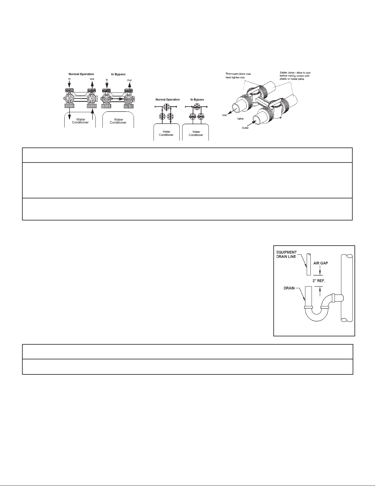
• Pay particular attention to correct orientation of control valve. Water flow should match arrow on control valve. The Inlet and Outlet of other water treatment
equipment products will vary depending on the control valve brand used.
IMPORTANT NOTES
• The system should be installed on cold water lines only.
• Failure to follow installation, operation and maintenance instructions will void warranty.