manuals.online logo
Brands
  1. Home
  2. •
  3. Brands
  4. •
  5. 3One data
  6. •
  7. Server
  8. •
  9. 3One data NP5100 Series User manual

3One data NP5100 Series User manual

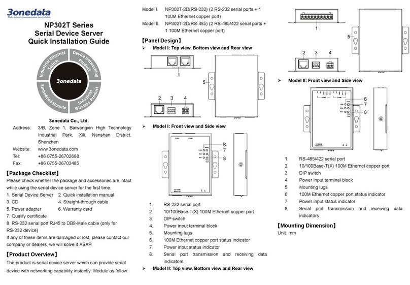
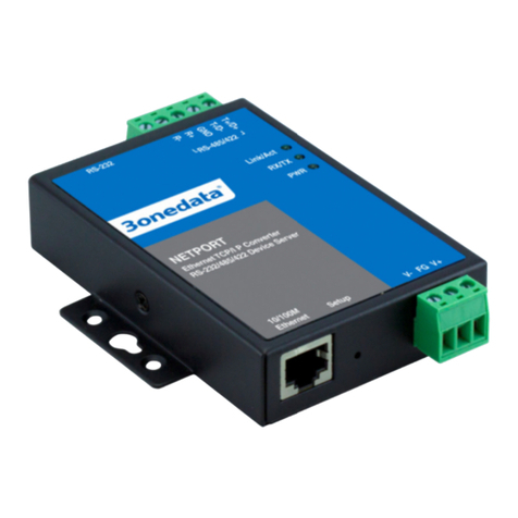
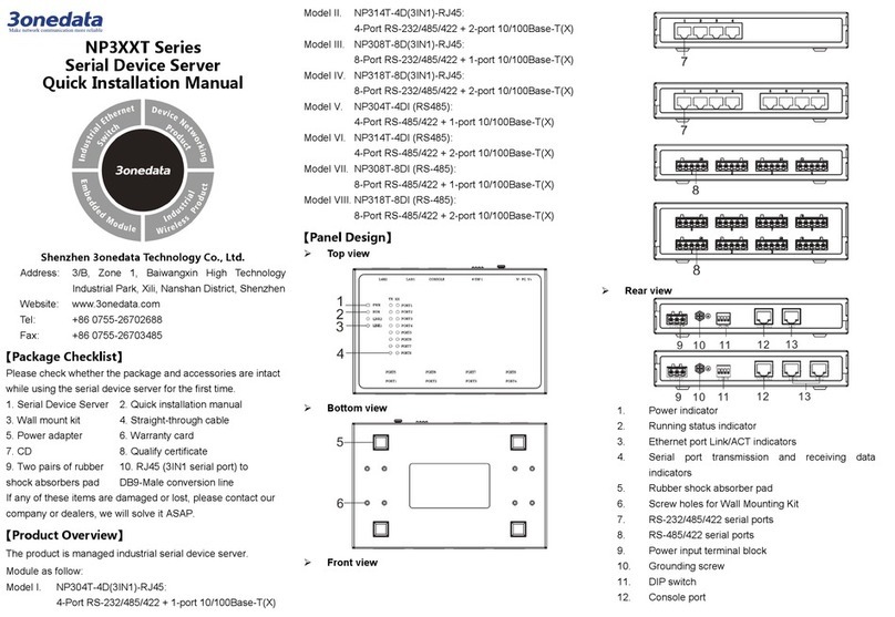
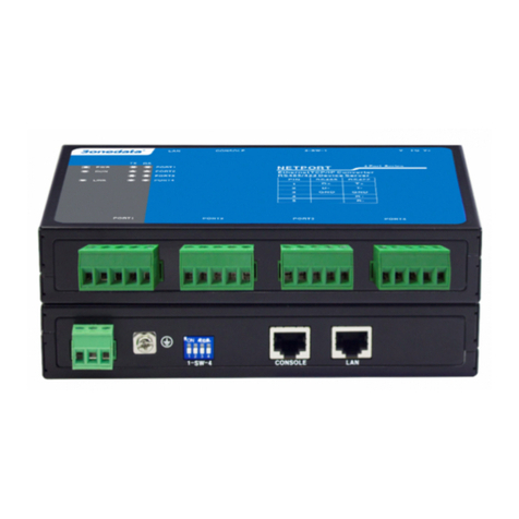
NP5100 Series
Serial Server
Quick Installation Guide
3onedata Co., Ltd.
Address:
3/B, Zone 1, Baiwangxin High Technology
Industrial Park, Xili, Nanshan District, Shenzhen
Website:
www.3onedata.com
Tel:
+86 0755-26702688
Fax:
+86 0755-26703485
【Package Checklist】
Please check the integrity of package and accessories while
first using the serial server.
1. Serial server
2. Quick installation guide
3. Power line x2
4. Network cable
5. Rack-mounting lug x2
6. Foot pad x4
7. Software installation CD
8. Warranty card
9. Certification
If any of these items are damaged or lost, please contact our
company or dealers, we will solve it ASAP.
【Product Overview】
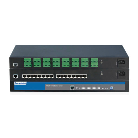
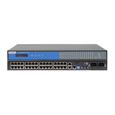
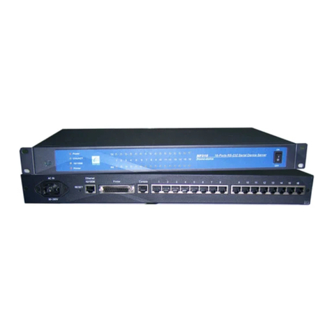
The series products are managed rack-mounted industrial
safe serial servers, including the following models:
Model I. NP5100-2T-32DI-32DI(3IN1)-RJ-OLED-2P(85-265
VAC) (2 10/100Base-T(X) copper ports + 32
RS-232/485/422 serial ports + 1 OLED display + 2
85-265VAC power supplies)
Model II. NP5100-2T-32DI(3IN1)-RJ-2P(85-265VAC) (2
10/100Base-T(X) copper ports + 32
RS-232/485/422 serial ports + 2 85-265VAC power
supplies)
Model III. NP5100-2T-16DI(3IN1)-RJ-OLED-2P(85-265VAC)
(2 10/100Base-T(X) copper ports + 16
RS-232/485/422 serial ports + 1 OLED display + 2
85-265VAC power supplies)
Model IV. NP5100-2T-16DI(3IN1)-RJ-2P(85-265VAC) (2
10/100Base-T(X) copper ports + 16
RS-232/485/422 serial ports + 2 85-265VAC power
supplies)
【Panel Design】
Front View
Model I, Model II
Model III, Model IV
Rear View
Model I
Model II
Model III
Model IV
Top view
Left view and right view
1. RS-232/485/422 serial port
2. 100M copper port
3. Console port
4. DIP switch
5. Grounding screw
6. TF card slot
7. AC power input
8. Lugs
9. Serial port transmitting indicator
10. Serial port receiving indicator
11. Running indicator
12. Power indicator
13. Copper port connection indicator
14. OLED display
15. Menu/Exit button
16. Page UP
17. Page Down
18. Select/confirm button
【Mounting Dimension】
Unit: mm
Notice Before Mounting:
Don't place or install the device in area near water or
moist, keep the relative humidity of the device
surrounding between 5%~95% without condensation.
Before power on, first confirm the supported power
supply specification to avoid over-voltage damaging the
device.
The device surface temperature is high after running;
please don't directly contact to avoid scalding.
【Rack-mounted】
This product adopts rack-mounting, mounting steps as below:
Step 1 Select the device mounting location to ensure
enough size.
Step 2 Adopt 4 bolts to install the mounting lugs in the
device position as figure below.
Step 3 Place the device in the rack; adopt 4 bolts to fix two
sides mounting lugs in the rack.
Step 4 Check and confirm the product is mounted firmly on
the rack, mounting ends.
【Disassembling Device】
Step 1 Device power off.
Step 2 Adopt screw driver to loosen the 4 bolts fixed on
the mounting lugs in the rack.
Step 3 Shift out the device from rack, disassembling ends.
Notice before power on:
Power ON operation: First insert the power supply
terminal block into the device power supply interface,
and then plug the power supply plug contact and power
on.
Power switch “—” means power ON, “O” means power
OFF.
Power OFF operation: First, put the powers switch to
the "O" side and then disconnect the power supply.
Finally disconnect the connector between the device and
the power cord. Please notice the operation order above.
【Power Supply Connection】
AC power supply
This device provides 2 AC power supply access
interfaces which come with a switch.
The power supply range is 85~265VAC
【Serial Port Connection】
This device provides 3IN1 serial port, which
supports RS232, RS485 and RS422 at the same
time. The interface type is RJ45 and its pin
definitions are as follows:
PIN 1 2 3 4 5 6 7 8
RS-232
DSR
RTS
GND
TXD
RXD
DCD
CTS
DTR
RS-485
—
—
GND
—
—
D-
—
D+
RS-422
—
R-
GND
R+
—
T-
—
T+
【Console Port Connection】
The series products provide 1 program debugging port based
on RS-232 serial port which can conduct device CLI command
management after connecting to PC. The interface adopts
RJ45 port, the RJ45 pin definition as follows:
Pin No.
2
3
5
Pin Definition
TXD
RXD
GND
【DIP Switch Settings】
The device provides 4-pin DIP switch for function
setting, in which ON is the enabled end. DIP switch
definition and operation method as follows:
DIP Definition Operation
1
Reserved
-
2 Restore
Factory
Settings
Set the switch to ON, wait for the
device to restart automatically, and
resume the switch before the restart
is completed.
3
Reserved
-
4
Reserved
-
【TF Card Slot】
This device provides 1 TF card slot. Using a screwdriver to
unscrew the screw behind the TF card slot with slight strength
and the card slot would pop up, then put TF card in the slot in
the right way. TF card could be used for device upgrade.
Before using it, please format the TF card into FAT32 format.
Notice:
In case of damaging TF card, user needs to power off
the device first to change the TF card.
【Set OLED Display】
Model I and model III of the device provide liquid crystal
display screens. Under normal working conditions, the liquid
crystal display is dark and shows the IP address of LAN1.
User can press the button to change the settings and query
accordingly:
Key
Name
Command
MENU
Menu/Exit
Enter Main Menu/Back
︿
Page UP
Select the last target
﹀
Page Down
Select the next target
SEL
Select/confirm
Select selected item
Display resolution is 128*16, support numbers, English case, ".
", "-", "_", "↑", "↓" and other characters, support single line left
and right scroll. Supports cursor blinking to determine the
current cursor position. Trigger the button, the screen light is
on. If there is no new operation for 30s, the screen would go
into sleep state.
Detailed operation steps of OLED display screen are as
follows:
Step 1 Start up, the first line shows the device name, the
second line shows the LAN1 IP address.
Step 2 Trigger the MENU key to enter the menu interface,
options:
-Server setting: basic information of the device,
please skip to step 3 and step 6 for this
setting;
-Network setting: network configuration,
please skip to step 5 and step 6 for this
setting;
-Save/Restart: restart the device, skip to step 6
for this setting.
Step 3 Select Server setting on the Menu interface, trigger
SEL key, enter the configuration interface of Server
setting, options:
-Serial number (read only);
-Server name (read only);
-Firmware ver (read only);
-Model name (read only);
Step 4 Select Network setting on the Menu interface,
trigger SEL key, enter the configuration interface of
Network setting, options:
-LAN mode: network port mode, which
supports single IP and dual IP configuration;
-Mode config: single IP mode configuration,
supporting Redundancy mode and Exchange
mode configuration;
-LAN 1: network card 1 configuration
-LAN 2: network card 2 configuration
Note:
"Mode config" and "LAN 1" should be configured when
"LAN mode" is "Single IP". "LAN1" and "LAN 2"
should be configured when "LAN mode" is "Dual IP".
Step 5 Select LAN 1(LAN 2) on the Network setting
interface, trigger SEL key, enter the configuration
interface of LAN 1(LAN 2), options:
-Ethernet status: network card state (read
only);
-MAC address: MAC address (read only);
-IP config: IP configuration method (trigger
SEL key configuration)
Options: STATIC, DHCP, BOOTP;
-IP address (read-write);
-Netmask (read-write);
-Gateway: default gateway (read-write).
Note:
When the configuration needs to be modified, it can be
triggered by ∧and ∨keys to change the value.
Step 6 Select Save/Restart on the Menu interface, trigger
SEL key, enter the configuration interface of
Save/Restart, options:
-Restart: reboot the device.
Notice:
Select Restart, and the interface first displays the
Disable option (prevent pressing the key too long and
misoperation), which can trigger the ﹀key, select the
Enable option, and then trigger the SEL key to restart
the device.
【Checking LED Indicator】
The series products provide LED indicators to monitor the
device working status with a comprehensive simplified
troubleshooting; the function of each LED is described in the
table as below:
LED
Indicate
Description
POWER
(1-2)
ON PWR is connected and running
normally
OFF PWR is disconnected and
running abnormally
RUN
Blinking
The system is running normally
OFF The system is not running or
running abnormally
ON
System is running abnormally
Save/Restart
Restart
LAN 1
Ethernet status
Network setting
LAN mode
Server setting
Serial number
Main menu
Server setting
Device Server
192.168.001.254
LED
Indicate
Description
Link(1-2
ON Port has established valid
network connection
Blinking Port is in a network
communication status
OFF Port hasn’t established valid
network connection.
TX(1-32)OFF
Serial port is not transmitting
data or transmitting data
abnormally
Blinking
Serial port is transmitting data.
RX(1-32)OFF Serial port is not receiving data
or receiving data abnormally
Blinking
Serial port is receiving data.
【Logging in to WEB Interface】
This device supports WEB management and configuration.
Computer can access the device via Ethernet interface. The
way of logging in to device’s configuration interface via IE
browser is shown as below:
Step 1 Configure the IP addresses of computer and the
device to the same network segment (The network
segment of Network Port 1 is 1, and the network
segment of network port 2 is 8), and the network
between them can be mutually accessed.
Step 2 Enter device’s IP address in the address bar of the
computer browser.
Network Port 1:
Network Port 2:
Step 3 Enter device’s username and password in the login
window as shown below.
Step 4 Click “Login” button to login to the WEB interface of
the device.
Note:
The default IP address of the device Network port 1 is
“192.168.1.254”, the default IP address of the network
port 2 is “192.168.8.254”.
The default user name and password of the device are
“admin”.
If the username or password is lost, user can restore it to
factory settings via management software; all modified
configurations will be cleared after restoring to factory
settings, so please backup configuration file in advance.
Please refer to user manual for specific configuration
method of logging in to WEB interface and other
configurations about network management function.
【Specification】
Panel
100M copper port 10/100Base-T(X) self-adapting
RJ45 port, half/full duplex
self-adaption or forced working
mode, support MDI/ MDI-X
self-adaption
Serial Port 3IN1 serial port, adopts RJ45,
supports 15KV ESD protection
Console port CLI command management
port (RS-232), RJ45
Indicator Power indicator, running status
indicator, copper port
connection status indicator,
serial port receiving indicator,
serial port transmission
indicator
OLED display
Menu/Exit, page up, page
down, select/confirm
Power supply
Input power supply
85~265VAC
Access terminal block Support single-
phase socket
with rocker switch
Power consumption
No-load
5.6W@220VAC
Full-load
13.2W@220VAC
Working Environment
Working temperature
-40
~
75
℃
Storage temperature
-40
~
85
℃
Working humidity
5%
~
95% (no condensation)
Protection grade
IP40 (metal shell)

This manual suits for next models

2

Other 3One data Server manuals

3One data NP301 User manual

3One data

3One data NP301 User manual

3One data NP308T-8D User manual

3One data

3One data NP308T-8D User manual

3One data NP318T-8DI User manual

3One data

3One data NP318T-8DI User manual

3One data NP30XT series User manual

3One data

3One data NP30XT series User manual

3One data NP5000 Series User manual

3One data

3One data NP5000 Series User manual

3One data NP3116T Series User manual

3One data

3One data NP3116T Series User manual

3One data NP302T Series User manual

3One data

3One data NP302T Series User manual

3One data NP302T Series User manual

3One data

3One data NP302T Series User manual

3One data NP316 User manual

3One data

3One data NP316 User manual

3One data CP202-2CI User manual

3One data

3One data CP202-2CI User manual

3One data NP301 Operating and maintenance instructions

3One data

3One data NP301 Operating and maintenance instructions

3One data NP318T-8DI Operating and maintenance instructions

3One data

3One data NP318T-8DI Operating and maintenance instructions

3One data NP Series User manual

3One data

3One data NP Series User manual

3One data NP3 T Series Operating and maintenance instructions

3One data

3One data NP3 T Series Operating and maintenance instructions

3One data NP318T-8DI User manual

3One data

3One data NP318T-8DI User manual

3One data NP5100 Series User manual

3One data

3One data NP5100 Series User manual

3One data ICP222-2F-2CI Operating and maintenance instructions

3One data

3One data ICP222-2F-2CI Operating and maintenance instructions

3One data NP316Series User manual

3One data

3One data NP316Series User manual

3One data CP202-2CI User manual

3One data

3One data CP202-2CI User manual

Popular Server manuals by other brands

NEC NEC Express5800 Series user guide

NEC

NEC NEC Express5800 Series user guide

HP BL920s Gen9 Product End-of-Life Disassembly Instructions

HP

HP BL920s Gen9 Product End-of-Life Disassembly Instructions

TimeTools DirekTronik 119-0219 T300 Hardware installation guide

TimeTools

TimeTools DirekTronik 119-0219 T300 Hardware installation guide

Dell PowerEdge R230 Getting started

Dell

Dell PowerEdge R230 Getting started

Silicon Graphics UV 3000 user guide

Silicon Graphics

Silicon Graphics UV 3000 user guide

NEC Express5800/320Ma Planning guide

NEC

NEC Express5800/320Ma Planning guide

Fujitsu PRIMERGY TX120 S2 Service supplement

Fujitsu

Fujitsu PRIMERGY TX120 S2 Service supplement

Oracle SPARC M8 Security guide

Oracle

Oracle SPARC M8 Security guide

Dell PowerEdge R410 Getting started

Dell

Dell PowerEdge R410 Getting started

Dell PowerEdge R900 installation guide

Dell

Dell PowerEdge R900 installation guide

Lenovo ThinkServer RD450 Product guide

Lenovo

Lenovo ThinkServer RD450 Product guide

Sapido Gr-1100 user manual

Sapido

Sapido Gr-1100 user manual

GrandTec GRAND Wi-Fi VIDEO SERVER PRO user manual

GrandTec

GrandTec GRAND Wi-Fi VIDEO SERVER PRO user manual

Dell PowerEdge 1750 Information update

Dell

Dell PowerEdge 1750 Information update

HP ProLiant XL730f Gen9 Server User and maintenance guide

HP

HP ProLiant XL730f Gen9 Server User and maintenance guide

Lenovo ThinkServer RS110 Guías del usuario

Lenovo

Lenovo ThinkServer RS110 Guías del usuario

HPE ProLiant EC200a Maintenance and service guide

HPE

HPE ProLiant EC200a Maintenance and service guide

Hitachi Advanced Server HA810 G2 user guide

Hitachi

Hitachi Advanced Server HA810 G2 user guide

manuals.online logo
manuals.online logoBrands
  • About & Mission
  • Contact us
  • Privacy Policy
  • Terms and Conditions

Copyright 2025 Manuals.Online. All Rights Reserved.