8x8 Inc 6739i Assembly instructions

onsOptions
Callers
Callers
Directory
Directory
Services
Services
Conf
Conf
Transfer
Transfer
Messages
Messages
Mute
Mute
Speaker/
Speaker/
Headset
Headset
Goodbye
Goodbye
Redial
Redial
Hold
Hold
Line 1
Line 1
Line 2
Line 2
Line 3
Line 3
www.8x8.com | 1.888.898.8733
User
Reference
Manual
6739i
IP Phone
Options
Callers
Directory
Services
Conf
Transfer
Messages
Mute
Speaker/
Headset
Goodbye
Redial
Hold
Line 1
Line 2
Line 3


v
Table of Contents
Table of Contents
Introduction...................................................................................... 1
Phone Features.............................................................................................................. 1
Requirements.................................................................................................................. 2
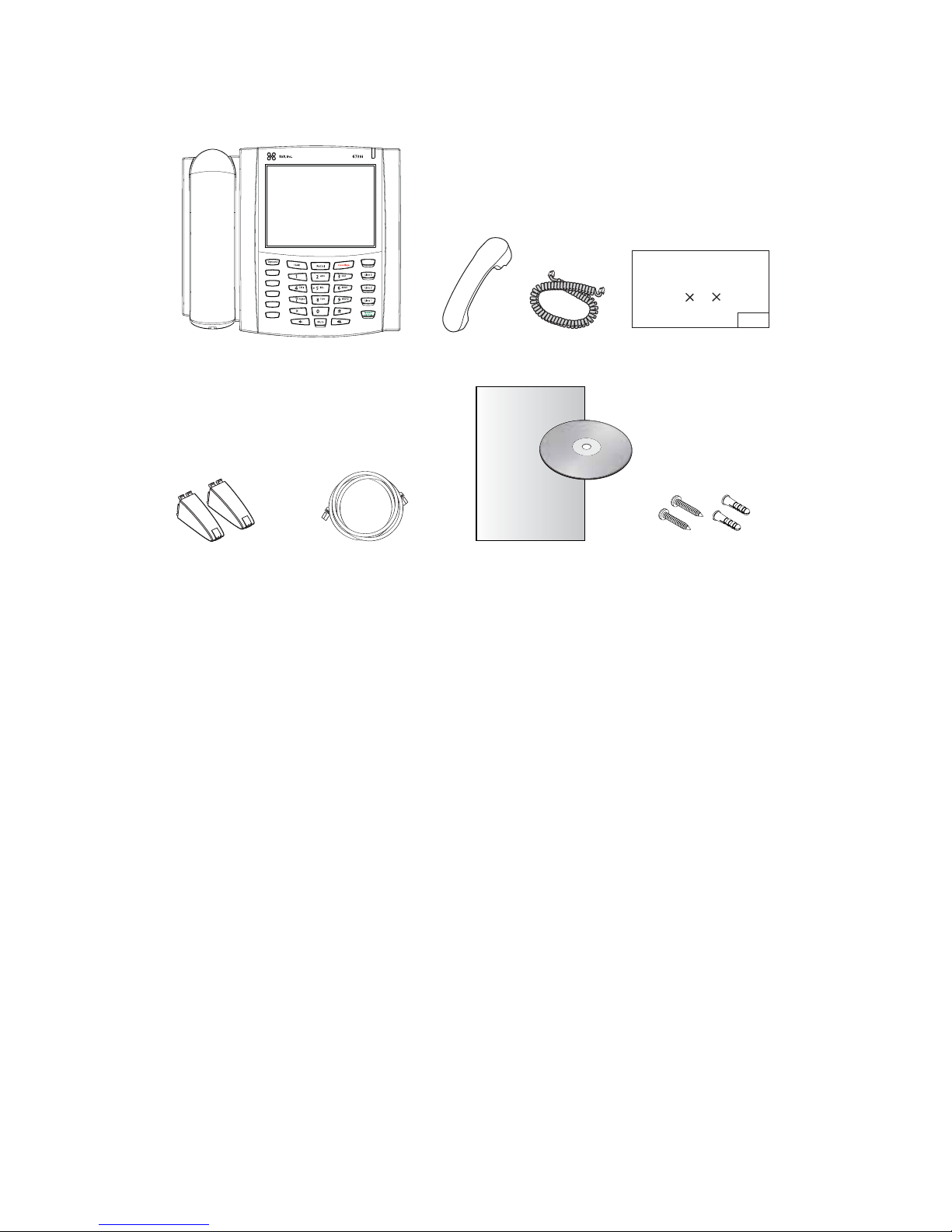
Phone Parts....................................................................................... 3
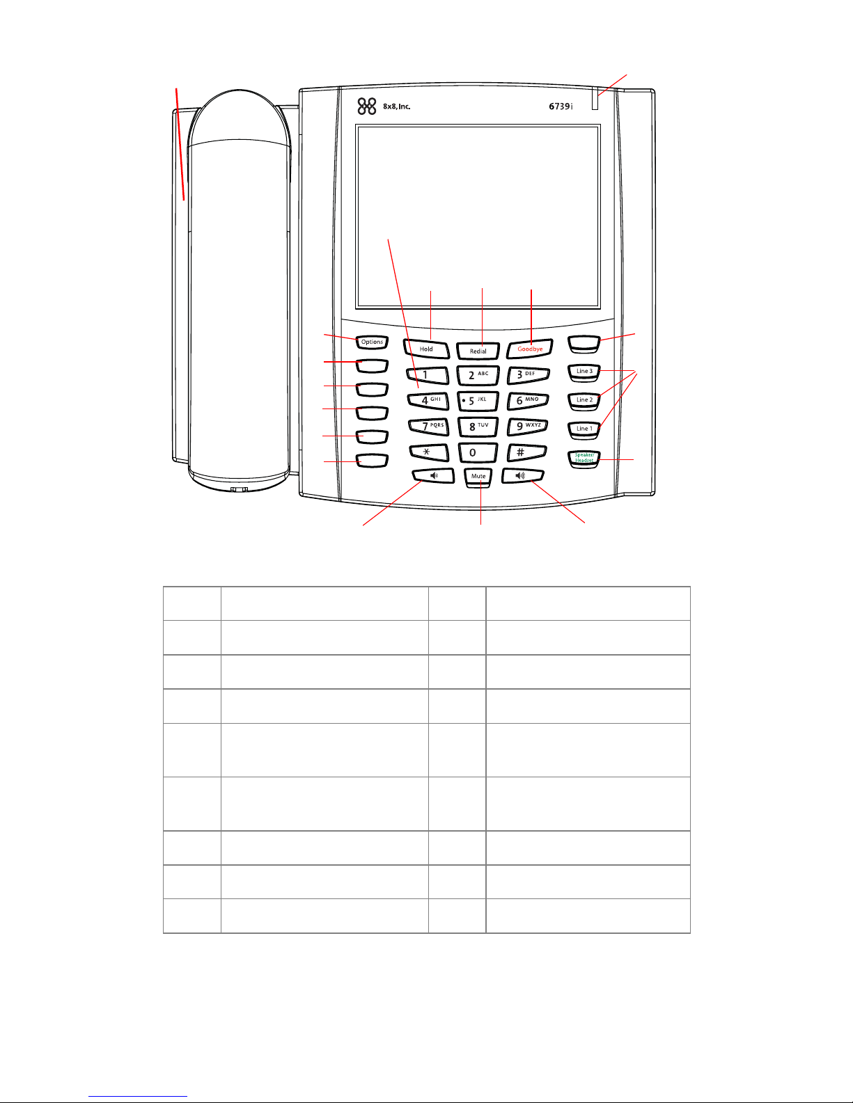
Key Panel .......................................................................................... 4
Key Descriptions............................................................................... 5
Installation and Setup....................................................................... 7
Direct or Shared Network Connection..................................................................... 7
Connecting to the Network and to Power............................................................... 9
Connecting a Handset, Headset, or DHSG Headset......................................... 11
Desk or Wall Installation............................................................................................. 13
Customizing your phone................................................................. 16
Accessing Your Options via the Phone UI............................................................. 17
Accessing Your Options via the 8x8 Web Phone UI .......................................... 17
IP Phone Features ........................................................................... 18
Other Phone Features..................................................................... 20
Adjusting the Volume.................................................................................................. 21
Status Lights (LEDs)................................................................................................... 21
Call Timer....................................................................................................................... 21
Call Forward.................................................................................................................. 22
Phone Status................................................................................................................ 22
User Password............................................................................................................. 22
6739i Softkeys............................................................................................................. 22
Pre-Programmed Softkeys......................................................................................... 23
Shared Line/Call Appearance................................................................................... 24
Using a Headset with your Telephone.................................................................... 24
Using the Telephone ....................................................................... 25
To Call an Outside Number....................................................................................... 25
To Call Another Extension ......................................................................................... 25
Making a Call................................................................................................................ 25
Receiving a Call........................................................................................................... 25
Troubleshooting Solutions............................................................... 26


Model 6739i IP Phone Installation Guide 1
Introduction
Introduction
Congratulations on purchasing 8x8 Virtual Office and IP Telephone. Simply plug
in your IP phone into your network to access your advanced business-class
voice features.
Phone Features
• 5.7" VGA Thin Film Transistor (TFT) technology graphical LCD with touch
screen and backlight capabilities
• Bluetooth headset support
• 3 call appearance line keys with LEDs
•USBjack
• Full-duplex speakerphone for handsfree calls
• Headset support jack
• DHSG headset jack
• Legacy Expansion Module support
• Next generation Expansion Module support
• Built-in-2-port, 10/100/1000 Ethernet switch - lets you share a connection
with your computer.
• Inline power support (based on 802.3af Power-over-Ethernet (PoE)
standard) which eliminates power adapters
• AC power adapter (sold separately)

2Model 6739i IP Phone Installation Guide
Introduction
Requirements
The 6739i IP Phone requires the following environment:
• SIP-based IP PBX system or network installed and running with a SIP
account created for the 6739i phone.
• Access to a Trivial File Transfer Protocol (TFTP) server, File Transfer Protocol
(FTP) server, Hypertext Transfer Protocol (HTTP) server, or Hyper Text Trans-
fer Protocol over Secure Sockets Layer (SSL) (HTTPS) server.
• Ethernet/Fast Ethernet LAN (10/100 BaseT), Gigabit Ethernet LAN (1000
BaseT) recommended
• Category 5/5e straight through cabling
• Power source
For Ethernet networks that supply in-line power to the
phone (IEEE 802.3af):
– For power, use the Ethernet cable (supplied) to connect from thephone
directly to the network for power. (No 48v AC power adapter required.)
For Ethernet networks that DO NOT supply power to the phone:
– (optional) For power, use the 48V AC Power Adapter (optional accessory)
to connect from the DC power port on the phone to a power source.
or– (optional) - For power, use a Power over Ethernet (PoE) power injector or
a PoE switch. A PoE power injector is available as an optional accessory
from 8x8, Inc. Contact your Administrator for more information.

Model 6739i IP Phone Installation Guide 3
Phone Parts
Phone Parts
When you unpack your phone, you should ensure that you have all of the
following items.
6739i SIP IP Phone
Wall Mount
Drilling Template
asdassa
asdadsda
Callers
Conf.
Trans fer
Services
Directory
Messages
6739i IP Phone
User Guide
Telephone Handset
Telephone
Base Desk Ethernet Cable
Handset Cord
6739i Installation
Wall Mount
Drilling Template
Legs Guide on CD Screws and
Anchors for
Wall Mounting

4Model 6739i IP Phone Installation Guide
Key Panel
Key Panel
Callers
Conf.
Transfer
Services
Directory
Messages
Volume Control (+)
Volume Control (-)
q
w
e
r
t
y
u
i
o
asd
f
g
h
j
k
l
q Handset a Hold key
w Speakerphone s Redial
e Message Waiting Lamp d Goodbye Key
r Options Key f Messages Key
t Callers List Key g Three (3) Call Appearance
Lines
y Directory Key h Speakerphone/Headset
Toggle Key
u Services Key j Mute Key
i Conference Key k Color LCD Touch Screen
o Transfer key l Keypad

Model 6739i IP Phone Installation Guide 5
Key Descriptions
Key Descriptions
Keys Key Description
Options Key - Accesses options to customize your
phone. Check with your System Administrator before
changing the administrator-only options.
Callers List Key - Accesses alist of calls receivedby
the phone.
Directory Key - Accesses a directory of names and
phone numbers (stored in alphabetical order).
Services Key - Accesses enhanced features and
services set up by your System Administrator.
Conference Key - Begins a conference call with the
active call.
Transfer Key - Transfers the active call to another
number.
Hold Key - Places an active call on hold. To retrieve a
held call, press the call appearance button beside
the light that is flashing.
Redial Key - Redials previously dialed numbers.
Pressing the Redial key twice simultaneously redials
the last dialed number.
Goodbye Key - Ends an active call. The Goodbye
key also exits an open list, such as the Options List,
without saving changes.
Messages Key - Accesses your phone’s voice
mailbox to retrieve and listen to stored messages.
Options
Options
Callers
Callers
Directory
Directory
Services
Services
Conf
Conf
Transfer
Transfer
Hold
Hold
Redial
Redial
Goodbye
Goodbye
Messages

6Model 6739i IP Phone Installation Guide
Key Descriptions
Line/Call Appearance Keys - Connect you to a line or
call. The 8x8 6739i IP Phone IP phone supports 3
line keys.
Speakerphone/Headset Key - Activates Handsfree
for making and receiving calls without lifting the
handset. When the audio mode option is set, this key
is used to switch between a headset and the
handsfree speakerphone. See "Customizing your
phone" on page 16 for more information.
Volume control key - Adjusts the volume for the
handset, headset, ringer, and handsfree speaker.
See "Adjusting the Volume" on page 21 for more
information.
Mute key - Mutes the microphone so that your caller
cannot hear you (the light indicator flashes when the
microphone is on mute).
Keys Key Description
Line 1
Line 2
Line 3
Speaker/
Speaker/
Headset
Headset
Mute

Model 6739i IP Phone Installation Guide 7
Installation and Setup
The 6739i can be setup to share a network connection with another network
device. Power can be provided by an AC adapter (optional accessory), an
802.3af compliant network power source, or witha PoE inline power injector
(optional accessory). It can also be installed on a desk or mounted on the wall.
Direct or Shared Network Connection
The phone can be set up as a direct network connection to the Ethernet wall jack
or as a shared network connection as a pass-through if connecting a
computer or another network device to the phone.
Direct Network Connection
Located at the top of the phone are two fully switched
10/100/1000 Mbps Ethernet cable ports. The port marked with LAN is used
to connect the phone to the network, as well as provide power to your phone
(if required). See the section "Connecting to the Network and to Power" on
page 9 for more information.
Ethernet
Ethernet
Cable
Cable
Other Network Devices
Separate
Separate
Network
Network
Jack
Jack
Network Jack
Network Jack
(if Inline power provided,
do not install the power adapter)
To Network
To Network
Power
Power
Adapter
Adapter
Power Adapter
Power Adapter
Connection
Connection

8Model 6739i IP Phone Installation Guide
Installation and Setup
Shared Network Connection
To connect a network device (such as a computer) to the phone, connect an
Ethernet cable into the network port on the top of the phone marked PC. Plug
the other end of the Ethernet cable into the network port on the network device
with which you are sharing the network connection.
Note: The PCjack on the 6739i does not supply inline power onto other network devices.
All Ethernet cables used must be category5/5e straight-through cables, such as the
cable provided with your phone
Ethernet
Cables
Other Network Devices
Network Jack
(if Inline power provided,
do not install the power adapter)
Power
Adapter
To Network
Power Adapter
Connection
To Other
Network Device

Model 6739i IP Phone Installation Guide 9
Installation and Setup
Connecting to the Network and to Power
Inline Power Provided
If your network provides 802.3af compliant in-line power, the phone is powered
through the network.
1. On the top of your phone, connect the Ethernet cable (provided with your
phone) into the network port marked with LAN.
2. Plug the other end of the Ethernet cable directly into the network jack on the
wall.
Ethernet
Cable
Network Jack
(if Inline power provided)
ToNetwork

10 Model 6739i IP Phone Installation Guide
Installation and Setup
Inline Power Not Provided
If your network does not provide 802.3af compliant in-line power, you need to
install the supplied AC adapter or the PoE inlinepower injector(optional
accessory).
1. On the top of your phone, connect the Ethernet cable (provided with your
phone) into the network port marked with LAN.
2. On the PoE power injector, plug the other end of the Ethernet cable into the
network jack marked as indicated in the following illustration.
3. On the PoE power injector, connect an additional Ethernet cable into the net-
work port as indicated in the following illustration.
4. Plug the other end of the Ethernet cable into the network jack on the wall.
5. Plug the PoE power injector into a power outlet.
Note: You should connect the power supply to a surge protector or power bar. All Ether-
net cables used must be category 5/5e straight-through cables, such as the
cable provided with your phone.
PoE
Power injector
(if Inline power is
not provided)
Power Outlet
ToNetwork
Jack
ToPhone
Ethernet
Cables
Network Jack
ToPower over Ethernet (PoE)

Model 6739i IP Phone Installation Guide 11
Installation and Setup
Connecting a Handset, Headset, or DHSG Headset
Handset
To connect the handset to the phone:
1. On the back of the phone base, locate the handset port marked . Insert
one end of handset cord into the port until it clicks into place.
2. Route the handset cord through the channel as shown in the illustration on
page 12.
3. Attach the handset to the other end of the handset cord.
Headset (Optional)
To connect a headset to the phone:
1. On the back of the phone base, locate the headset port marked . Insert
the headset cord into the port until it clicks into place.
2. Route the headset cord through the channel as shown in the above illustration
on page 12.
DHSG Headset (Optional)
You can attach an optional DHSG headset to the 6739i IP Phone if required.
To connect a DHSG headset to the phone:
1. On the back of the phone base, locate the DHSG port marked AUX.
2. Attach your 3rd party DHSG headset cable to 8x8’s DHSG jack.
Note: DHSG headsets may require further configuration before use. Refer to your headset
documentation or contact your headset vendor for more information.

12 Model 6739i IP Phone Installation Guide
Installation and Setup
Attaching Cords and Cables
Ports on Back of Phone Base
Attaching Cords to the Phone Base
Attach cord
to handset
Route cords through
applicable channels
Handset Port
Headset Port
DHSG Port

Model 6739i IP Phone Installation Guide 13
Installation and Setup
Desk or Wall Installation
Install on the Desk
The desk installation for the 6739i IP phone consists of two legs that attach to
the back of the phone near the top corners. A total of four different viewing
angles allows users to personalize their phone viewing preference.
1. Attach each leg by inserting the tabs on the leg into the slots on the bottom of
the phone. There are three pair of leg slots on each corner of the phone; each
leg uses two pairs (1&2, or 2&3) giving two leg positions designating different
viewing angles. Furthermore, the legs can be reversed which offer two addi-
tional viewing angles.
2. For a higher viewing angle, use the second and third slots from the top.
3. For a lower viewing angle, use the first and second slots from the top.
4. Push the stand towards the phone until it snaps into place.
Three leg slot locations
for customizing the height
of the desk phone.
Total 4 Viewing Angles
20.7 deg.
Incline Angle 23.3 deg.
Incline Angle 26.6 deg.
Incline Angle 30.9 deg.
Incline Angle

14 Model 6739i IP Phone Installation Guide
Installation and Setup
Install on the Wall
The 6739i IP phone has two pre-drilled wall mounting holes on the back of the
phone.
1. Using the provided wall mount drilling template, locate and mark the position
for the mounting screws on the wall. Depending on the wall type, you may
need to use wall anchors. Both the screws and wall anchors are included with
your phone.
2. Place the wall mount holes on the phone over the screw heads on the wall
and pull down to lock the phone in.
Note: You may wish to purchase a short Ethernet cable from a local supplier for a wall
installation. Also, if 802.3af compliant in-line power is not provided on your net-
work, and you are installing the 6739i on a wall using a PoE in-line power injector,
you may also wish to use an equivalent flat Ethernet cable rather than the one pro-
vided.
3. In the handset cradle, there is a small clip that sits flush with the cradle sur-
face. Using a small flathead screwdriver, pull the clip up and remove it from
the phone.
4. With the arms on the clip facing you and the flat side of the clip towards the
phone, turn the clip 180 degrees and reinsert it back into the clip cavity in the
phone’s cradle.
5. Push the clip in until it snaps into the slot flush with the surface and only the
Wall Mount Holes

Model 6739i IP Phone Installation Guide 15
Installation and Setup
legs on the clip are sticking up.
6. Place the handset into the phone’s cradle, inserting the legs on the clip into
the square hole on the handset. This allows the handset to rest in the cradle in
a vertical position without slipping off when the phone is installed on the wall.
Remove clip, turn 180
degrees, and reinsert
clip.
Clip
Square Hole
on Handset

16 Model 6739i IP Phone Installation Guide
Customizing your phone
Your 6739i is a feature-rich IP Phone that allows you to customize and configure
it with the touch of your finger and/or the press of a button.
You can access configuration options by pressing the button on the
phone. You can also access options using the 8x8 Web User Interface (UI) to
your phone.
The following table indicates the options and the method you can use to access
these options on your phone.
Phone Option Access from
Phone UI
Access from
8x8 Web
Phone UI
Set Audio XX
Ring Tone XX
Tone Set XX
Display XX
Brightness XX
Calibrate Screen XX
Set Time XX
Time Formats XX
Date Format XX
Time Server 1 XX
Time Server 2 XX
Language XX
Bluetooth
Enable XX
Device Name XX
Add Device XX
Status
Network Status XX
Firmware Version XX
Options
Options
Table of contents
Other 8x8 Inc IP Phone manuals
Popular IP Phone manuals by other brands

Nortel
Nortel 2001 user guide

Avaya
Avaya IP Office 9608 Administrator's guide

Atlantis Land
Atlantis Land A02-IPH102 specification

Samsung
Samsung OFFICESERV 100 Series System administration & special features guide

Avaya
Avaya 4630 quick reference

Patton electronics
Patton electronics SL4050/10 Getting started guide