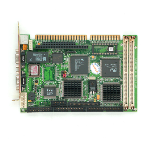
Aaeon SBC-356 User manual

SBC-356
Half-size All-in-one 386SX-40 CPU card

FCC STATEMENT
THIS DEVICE COMPLIES WITH PART 15 FCC RULES.
OPERATIONISSUBJECT TOTHE FOLLOWINGTWO
CONDITIONS:(1) THISDEVICE MAY NOT CAUSE HARM-
FULINTERFERENCE. (2)THIS DEVICEMUST ACCEPT
ANYINTERFERENCE RECEIVEDINCLUDING INTERFER-
ENCETHATMAYCAUSE UNDESIRED OPERATION.
THIS EQUIPMENT HAS BEEN TESTED AND FOUND TO
COMPLY WITH THE LIMITS FOR A CLASS"A" DIGITAL
DEVICE, PURSUANT TO PART 15 OF THE FCC RULES.
THESE LIMITS ARE DESIGNED TO PROVIDE REASON-
ABLE PROTECTION AGAINTST HARMFUL INTERFER-
ENCE WHEN THE EQUIPMENT IS OPERATED IN A
COMMERCIAL ENVIRONMENT. THIS EQUIPMENT
GENERATES,USES, AND CAN RADIATE RADIO
FREQENCY ENERGYAND , IFNOT INSTATLLEDAND
USED IN ACCORDANCE WITH THE INSTRUCTION
MANUAL, MAY CAUSEHARMFUL INTERFERENCE TO
RADIO COMMUNICATIONS.OPERATION OF THIS
EQUIPMENT IN A RESIDENTIAL AREA IS LIKELY TO
CAUSE HARMFUL INTERFERENCE IN WHICH CASE
THE USER WILL BE REQUIRED TO CORRECT THE
INTERFERENCE AT HIS OWN EXPENSE.

Copyright Notice
This document is copyrighted, 1997, by AAEON Technology Inc.
All rights are reserved. AAEON Technology Inc. reserves the
right to make improvements to the products described in this
manual at any time without notice.
No part of this manual may be reproduced, copied, translated or
transmitted in any form or by any means without the prior written
permission of AAEON Technology Inc. Information provided in
this manual is intended to be accurate and reliable. However,
AAEON Technology Inc. assumes no responsibility for its use, nor
for any infringements upon the rights of third parties which may
result from its use.
AMI, Analog Device, Award, Burr-Brown, Carray, DR-DOS IBM,
AT, INM XT, Personal System/2, PS/2, Micro Channel, PC-DOS,
Inlog, Jactech, Microsoft, MS-DOS, NEC, Singular and TI are
Registered trademarks.
Part No. 2007356000 1st Edition
Printed in Taiwan Oct 1997

Packing list
Before you begin installing your card, please make sure that the
following materials have been shipped:
• 1 SBC-356 CPU card
• 1 6-pin mini-DIN dual outlet adapter for keyboard and PS/2
mouse
• 1 Hard disk drive (IDE) interface cable (40 pin)
• 1 Floppy disk drive interface cable (34 pin)
• 1 parallel port adapter (26-25 pin) and COM port (10-9 pin)
adapter kit
• 1 utility disk with VGA utility programs and drivers
If any of these items are missing or damaged, contact your
distributor or sales representative immediately.

Contents
1 General Information ........................... 1
Introduction ............................................................................ 2
Specifications .......................................................................... 3
Board layout ........................................................................... 5
Carddimensions ..................................................................... 6
2 Installation ........................................... 7
Jumpersandconnectors ........................................................ 8
Locating jumpers and connectors....................................... 10
Setting jumpers ......................................................................11
Safetyprecautions ................................................................ 12
Installing DRAM (SIMMs) .................................................. 13
Watchdogtimersetup(JP9,JP14) ....................................... 14
PS/2 Mouse Setup (JP8)....................................................... 17
FlashEPROMSelection(JP15)........................................... 17
COM4 Communication setup (JP1, JP12, JP13) .............. 18
IDEHardDiskI/F(CN10) ................................................... 19
Floppy disk Connector I/F (CN7) ....................................... 20
SerialcommunicationI/F
(CN17, CN14, CN15, CN16, CN 12) ................................... 21
ParallelPortI/F(CON2)...................................................... 23
VGA Monitor I/F (CN18) .................................................... 24
FlatPanelI/F(CN11)............................................................ 25
Cable and switch connections
(CN1, CN3, CN4, CN5, CN19, CN21, CN6) ...................... 26
DiskOnChip Installation (U9, JP11) ................................... 27

3 AMIBIOS Setup .................................... 29
Generalinformation............................................................. 30
StandardCMOSSetup ........................................................ 31
AdvancedCMOSSetup ....................................................... 33
AdvancedChipsetSetup ...................................................... 40
ChangeSuppervisorPassword ............................................ 41
Auto Configuration with Optimal settings......................... 41
Auto Configuration with Fail Safe settings ........................ 41
Save Settings and Exit .......................................................... 41
Exit Without saving .............................................................. 42
4 SVGA Setup ......................................... 43
Windows 3.1 .......................................................................... 44
Driverinstallation-Windows Setup........................................ 44
DOS ....................................................................................... 45
SOFTWAREUTILITIES ...................................................... 47
The CHIPSCPL utility program ............................................. 47
Installingtheutility .................................................................. 47
Howto use the uitlity ............................................................... 47
A Watchdog Timer Demo Program .... 49
B Installing PC/104 Modules ................. 51
Installing PC/104 modules ................................................... 52
C LCD Display BIOS Configuration ........ 55

Chapter 1 General Information 1
CHAPTER
1
GeneraI
Information
This chapter provides background
information for the SBC-356.
Sections include:
· Card specifications
·Board layout

2SBC-356 User's Manual
Introduction
The SBC-356 is an all-in-one CPU card that intergrates VGA
display and Disk-On-Chip card. The SBC-356 is a half-sized card
that is based on the 386SX CPU running at 40MHz and supports
up to 32 MB of Fast Page DRAM. The card has an on-board
Watch-Dog timer, a Buzzer, and battery-backed Real Time Clock.
It comes with AMI BIOS which is mapped to the upper 64K of
memory.
The SBC-356 provides a floppy disk controller, an IDE disk
controller, four high speed serial prots (RS-232/422/485) and
one Multi-mode parallel port (ECC/EPP/ECP). The SBC-356 is
also equipped with VGA controller. It uses C&T F65545 ISA-bus
VGA controller which provides a flat panel I/F (interface) to
support panel displays.
For applications that require Solid State Disk (SSD) memory, the
SBC-356 is equipped with one 32-pin DIP IC socket which can
accommodate DiskOnChip Solid State Disk memory. The SBC-
356 supports from 2MB up to 24MB of SSD memory.

Chapter 1 General Information 3
Specifications
· CPU: 386SX 40 MHz
· Bus interface: ISA (PC/AT) bus
· Data Bus: 16 bit
· Chipset: ALI M6117B (Embedded CPU-386SX)
· RAM memory: Fast Page DRAM 512KB to 16 MB with access
time 70 ns or faster. Uses two 72 pin SIMM sockets
· Dsiplay controller: C&T F65545 ISA-bus VGA controller
· Video memory: two 256k*16 DRAM (1MB) and one 256K*16
DRAM(512KB) used for improving performance with color DSTN
panels
· IDE HDD interface: One primary IDE hard disk drive interface
supports up to two IDE HDDs
· Floppy disk drive interface: One floppy disk drive interface
supports up to two floppy disk drives, 5.25"(360KB and 1.2MB) and /
or 3.5" (720KB, 1.44 and 2.88MB)
· Parallel port: One Multi-mode Parallel port(ECC/EPP/ECP
models)
· Serial port: Four high speed serial ports. Three RS-232 and one
RS-232/RS-422/RS-485
· Real time clock: Dallas DS12B887
· Watchdog timer: Jumper configured time interval: 1, 2, 10, 20, 110,
120 seconds
· PC/104 connector: 104 pins for 16-bit bus. Supports PC/104
modules such as Flash/RAM/ROM disk modules and/or PCMCIA
modules
· Solid State Disk (SSD) interface: One 32-pin DIP socket supports
M-system Disk-On-Chip 2000 series, memory capacity from 1MB to
24MB.
· DMA channels: 7

4SBC-356 User's Manual
· Interrupt channels: 15
· Keyboard interface: Yes
· PS/2 mouse support: Yes
· Voltage requirements: +5V, +12V and -12V
· Operating temperature: +0°C to 60°C
· Storage temperature: -25°C to +85°C
· Operating humidity range: 0 to 90% non-condensing
· Storage humidity range: 0 to 90% non-condensing
· Weight (without memory): 260g
· Dimensions: 19.0(L)*12.5(W)*2.5(H)cm

Chapter 1 General Information 5
Board layout

6SBC-356 User's Manual
Card dimensions
26.00
185.00
19.00
80.65
73.66
122.00
112.00
4.50
SBC-356 386 CPU CARD WITH VGA/PANEL REV. A1

Chapter 2 Hardware Configuration 7
CHAPTER
2
Installation
This chapter describes how to set up the
SBC-356 hardware, including instruc-
tions on setting jumpers and connecting
peripherals, switches and indicators. Be
sure to read all safety precautions before
you begin the installation procedure.

8SBC-356 User's Manual
Jumpers and connectors
Connectors on the board link it to external devices such as hard
disk drives, a keyboard or floppy drives. In addition, the board has
a number of jumpers that allows you to configure your system to
suit your application. The table below lists the function of each of
the board jumpers and connectors.
Name Function
CN1 Power connector
CN2 Printer I/F connector
CN3 External reset connector
CN4 Key lock
CN5 Speaker
CN6 HDD LED (indicator)
CN7 FDD I/F connector
CN8 PC/104 I/F (XT Bus)
CN9 PC/104 I/F (AT Bus)
CN10 HDD connector (Primary)
CN11 LCD panel I/F connector
CN12 Serial I/F #4 (RS-422/485)
CN14 Serial I/F #2 (RS-232)
CN15 Serial I/F #3 (RS-232)
CN16 Serial I/F #4 (RS-232)
CN17 Serial I/F #1 connector
CN18 VGA I/F connector
CN19 Keyboard connector
CN21 Keyboard/Mouse connector
U9 Disk On Chip socket
SM1-2 System DRAM socket
JP1 COM4 Communication I/F
JP8 PS/2 interrupt (IRQ12)
JP9 Watch-dog timer out active
JP11 Disk On Chip address selection (DiskOnChip
memory)

Chapter 2 Hardware Configuration 9
JP12 RS-422/485 RX control
JP13 RS-422/485 TX control
JP14 Watch-Dog Timer Timeout
JP15 Flash EPROM Select

10 SBC-356 User's Manual
SBC-356 386 CPU CARD WITH VGA/PANEL REV. A1
MEGA-KB-H-Q
DALLAS
DS12887A
ALI
M6117B
14.3C73
ALI
M5113
CHIPS
F65545 B2
DiskOnChip
UMC
UM8669F
BIOS
Locating jumpers and connectors
CN1
CN14
CN12
CN21
CN17
CN18
CN15 CN16
CN11
JP9
CN9
CN8
JP11
JP8
JP1
CN2
CN10
CN3
CN4
CN5
CN7
CN19
CN6
JP15
JP12
JP13
JP14
U9
SM1, SM2

Chapter 2 Hardware Configuration 11
Setting jumpers
You configure your card to match the needs of your application by
setting jumpers. A jumper is the simplest kind of electric switch.
It consists of two metal pins and a small metal clip (often
protected by a plastic cover) that slides over the pins to connect
them. To “close” a jumper you connect the pins with the clip. To
“open” a jumper you remove the clip. Sometimes a jumper will
have three pins, labeled 1, 2 and 3. In this case you would connect
either pins 1 and 2 or 2 and 3.
The jumper settings are schematically depicted in this manual as
follows:
A pair of needle-nose pliers may be helpful when working with
jumpers.
If you have any doubts about the best hardware configuration for
your application, contact your local distributor or sales represen-
tative before you make any changes.
Generally, you simply need a standard cable to make most
connections.
13
2
Open Closed Closed 2-3
1 2 3

12 SBC-356 User's Manual
Safety precautions
Warning! Always completely disconnect the power cord
from your chassis whenever you are working on
it. Do not make connections while the power is
on because sensitive electronic components can
be damaged by the sudden rush of power. Only
experienced electronics personnel should open
the PC chassis.
Caution! Always ground yourself to remove any static
charge before touching the CPU card. Modern
electronic devices are very sensitive to static
electric charges. Use a grounding wrist strap at
all times. Place all electronic components on a
static-dissipative surface or in a static-shielded
bag when they are not in the chassis.

Chapter 2 Hardware Configuration 13
Installing DRAM (SIMMs)
The SBC-356 are sold without system memory and disk on chip
memory. Memory must be installed prior to using the SBC-356.
The SBC-356 has 2 SIMM (Single In-line Memory Module)
DRAM module sockets. Each socket will accommodate a 72 pin
DRAM module - 1MB, 4MB or 16MB. The memory access time
should be 70ns or less. The SBC-356 can also accommodate
memory modules with parity check bit. EDO DRAM memory
modules are not supported by SBC-356.
Install memory as appropriate at locations SIMM1 - SIMM2.
1MS1MS1MS1MS1MS2MS2MS2MS2MS2MSyromeMlatoTyromeMlatoTyromeMlatoTyromeMlatoTyromeMlatoT
BM1BM1
BM1BM1BM2
BM4BM4
BM4BM4BM8
BM61BM61
BM61BM61BM23

14 SBC-356 User's Manual
Watchdog timer setup(JP9 and JP14)
The watch-dog timer is a circuit that should be refreshed periodi-
cally. If it is not refreshed within a certain time, the watch-dog
timer will automatically reset the system. This prevents a system
from hanging indefinitely. When the Watch-dog tmer is enabled,
the user must constantly refresh the Watch-dog timer within a
certain time (Eg. 10 seconds). If the user falls to do so, the
watch-dog timer will automatically reset the system or issue a
non-maskable interrupt (NMI).
JP9 determines the watch-dog timer function, it can disable the
watch-dog timer or connect watch-dog timer to reset trigger or
NMI trigger.
Watch-dog Timer Selection(JP9)
Disable Watch-dog timer
System Reset (Default)
NMI
1
2
3
1
2
3
1
2
3
Table of contents
Other Aaeon Computer Hardware manuals

Aaeon
Aaeon NanoCOM-WHU User manual

Aaeon
Aaeon NEZHA-N97 User manual

Aaeon
Aaeon PCM-6896 User manual

Aaeon
Aaeon AIOT-MSSP01 User manual

Aaeon
Aaeon GENE-APL6 User manual

Aaeon
Aaeon BOXER-6640M User manual

Aaeon
Aaeon GENE-QM57 User manual

Aaeon
Aaeon ETX-700 User manual

Aaeon
Aaeon HSB-440I User manual

Aaeon
Aaeon SBC-350A User manual

Aaeon
Aaeon SBC-411 User manual

Aaeon
Aaeon SBC-555 User manual

Aaeon
Aaeon PFM-336I User manual

Aaeon
Aaeon HSB-660S/I User manual
Aaeon
Aaeon BOXER-8120AI User manual

Aaeon
Aaeon COM-ICDB7 User manual

Aaeon
Aaeon PFM-620S User manual

Aaeon
Aaeon SBC-400 User manual
Aaeon
Aaeon SBC-656 User manual

Aaeon
Aaeon SBC-860 User manual