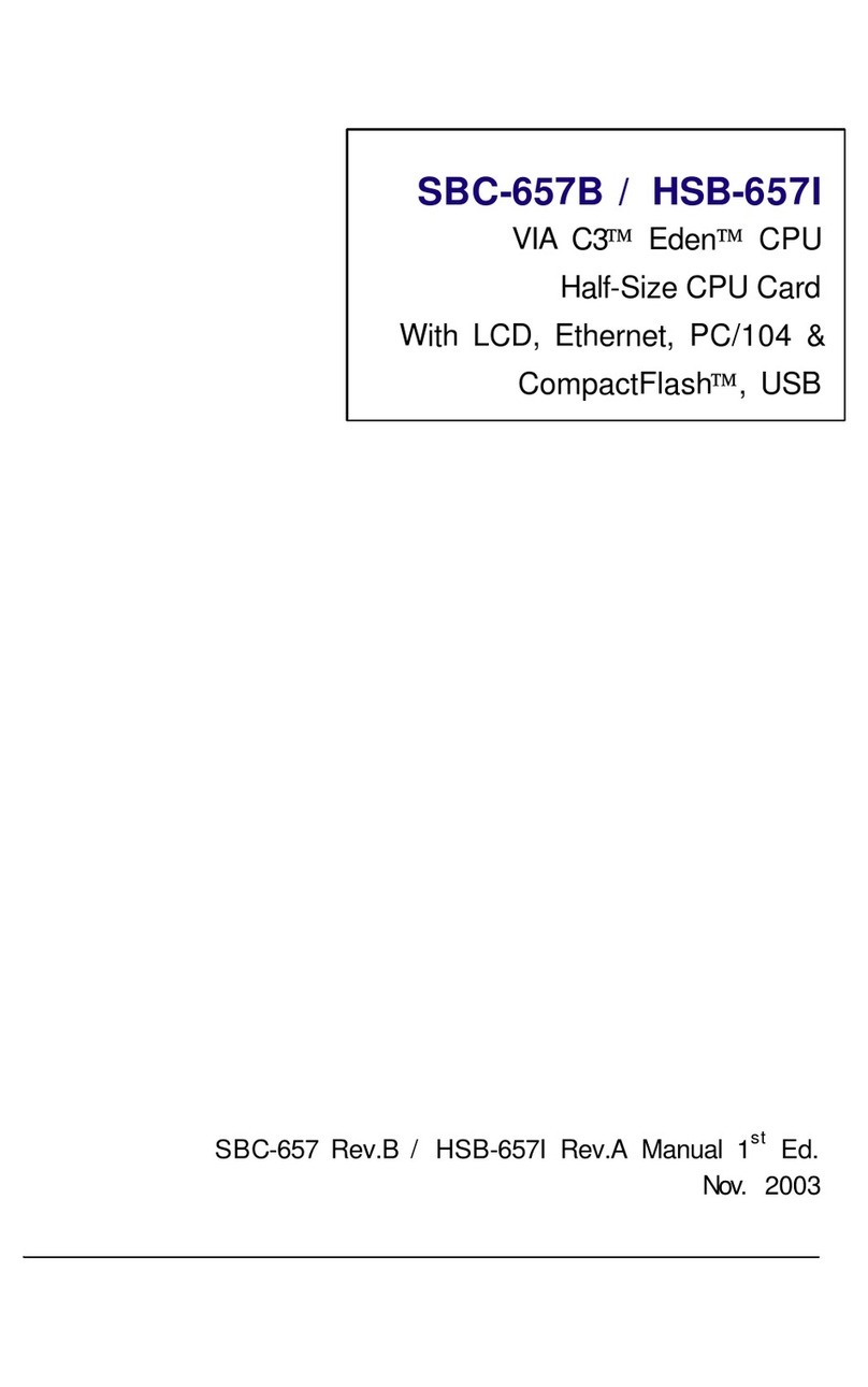
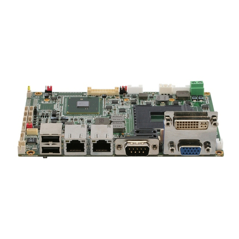
Aaeon SBC-555 User manual

SBC-554V
Half-size 586 CPU Card with PISA Bus
SBC-555
Half-size 586 CPU Card with ISA Bus

FCC STATEMENT
THIS DEVICE COMPLIES WITH PART 15 FCC RULES.
OPERATIONISSUBJECT TOTHE FOLLOWING TWO
CONDITIONS:(1) THIS DEVICE MAY NOT CAUSE HARM-
FULINTERFERENCE. (2) THIS DEVICE MUST ACCEPT
ANYINTERFERENCERECEIVEDINCLUDINGINTERFER-
ENCETHATMAYCAUSEUNDESIREDOPERATION.
THIS EQUIPMENT HAS BEEN TESTED AND FOUND TO
COMPLY WITH THE LIMITS FOR A CLASS "A" DIGITAL
DEVICE, PURSUANT TO PART 15 OF THE FCC RULES.
THESE LIMITS ARE DESIGNED TO PROVIDE REASON-
ABLE PROTECTION AGAINTST HARMFUL INTERFER-
ENCE WHEN THE EQUIPMENT IS OPERATED IN A
COMMERCIAL ENVIRONMENT. THIS EQUIPMENT
GENERATES,USES, AND CAN RADIATE RADIO
FREQENCY ENERGYAND , IF NOT INSTATLLEDAND
USED IN ACCORDANCE WITH THE INSTRUCTION
MANUAL, MAY CAUSE HARMFUL INTERFERENCE TO
RADIO COMMUNICATIONS.OPERATION OF THIS
EQUIPMENT IN A RESIDENTIAL AREA IS LIKELY TO
CAUSE HARMFUL INTERFERENCE IN WHICH CASE
THE USER WILL BE REQUIRED TO CORRECT THE
INTERFERENCE AT HIS OWN EXPENSE.

Copyright Notice
This document is copyrighted, 1997, by AAEON Technology
Inc. All rights are reserved. AAEON Technology Inc. reserves the
right to make improvements to the products described in this
manual at any time without notice.
No part of this manual may be reproduced, copied, translated or
transmitted in any form or by any means without the prior written
permission of AAEON Technology Inc. Information provided in
this manual is intended to be accurate and reliable. However,
AAEON Technology Inc. assumes no responsibility for its use,
nor for any infringements upon the rights of third parties which
may result from its use.
Acknowledgements
ALI is a trademark of Acer Laboratories, Inc.
AMD is a trademark of Advanced Micro Devices, Inc.
Award BIOS is a trademark of Award Sofeware International, Inc.
AutoCAD and AutoShade are trademarks of Autodesk, Inc.
CHIPS Logotype is a registered trademark; Chips 65554 is a
trademark of Chip and Technologies, Inc.
Cyrix is a trademark of Cyrix Corporation.
IBM, PC/AT, PS/2 and VGA are trademarks of International
Business Machines Corporation.
Intel and Pentium are trademarks of Intel Corporation.
Lotus, 1-2-3 an Symphony are trademarks of Lotus Development
Corp.
Microsoft Windows®, MS-DOS, Corporation Windows and
Microsoft are registered trademarks of Microsoft Corp.
SiS is a trademark of Silicon Integrated System Corp.
SMC is a trademark of Standard Microsystems Corporation.
TurboDLD Classic is a trademark of Panacea Inc.
UMC is a trademark of United Microelectronics Corporation.
WordPerfect is a trademark of WordPerfect Corporation.
VESA®is a registered trademark of Video Electronics Standards
Association.
All other product names or trademarks are properties of their
respective owners.
Part No.2007554001 SBC-554V/555 2nd Edition
Printed in Taiwan Nov. 1997

Packing list
Before you begin installing your card, please make sure that the
following materials have been shipped:
• 1 SBC-554V CPU card/ or SBC-555 CPU Card
• 1 6-pin mini-DIN dual outlet adapter for keyboard and PS/2
mouse
• 1 Hard disk drive (IDE) interface cable (40 pin)
• 1 Floppy disk drive interface cable (34 pin)
• 1 Parallel port adapter (26 pin) and COM2 adapter (9 pin) kit
• 4 Utility disks with CHIPS 65554 utility programs and drivers
If any of these items are missing or damaged, contact your
distributor or sales representative immediately.

Contents
Chapter 1: General Information .......................... 1
Introduction ............................................................................ 2
Features ................................................................................... 3
Specifications .......................................................................... 4
Board layout ........................................................................... 6
Carddimensions ..................................................................... 7
Chapter 2: Installation ......................................... 9
Jumpersand connectors ...................................................... 10
Locating jumpers and connectors........................................11
Setting jumpers ..................................................................... 12
Safetyprecautions ................................................................ 13
Installing the CPU ................................................................ 13
CPU Clock Ratio (JP1) .......................................................... 15
DRAM Voltage Setting (JP2) ................................................. 15
Vcorevoltage setting (JP4) ..................................................... 16
CPU I/O Voltage setting (JP3) ................................................ 17
PCI Bus Clock Sync / Async Mode settings (JP5) ................. 17
CPU External Clock Selection (JP6)....................................... 17
CPU Jumper Setting Example................................................. 18
LCD Panel's Voltage setting (JP7) .......................................... 19
Clear CMOS Data (JP8) ......................................................... 19
SSD Address settings (JP9) .................................................... 19
RS-232/422/485 selections (JP10) .......................................... 20
Hardware Reset (JP11)........................................................... 20
InstallingSIMMs.................................................................. 21
RemovingSIMMS .................................................................. 21
IDEhard drive connector (CN1) ......................................... 22
Connecting the hard drive ....................................................... 22
Floppy drive connector (CN2) ............................................. 23
Connecting thefloppy drive .................................................... 23

Display connections (LCD)(CN3) ....................................... 24
USB connnector (CN4) ........................................................ 25
Parallel port connector (CN5) ............................................. 25
Serial ports (CN6, CN7) ....................................................... 26
VGA connector (CN8).......................................................... 26
KB/PS2 Mouse connection (CN9)....................................... 26
Powersupplyconnector (POWER CON) (CN10).............. 27
Invertorconnector (CN11)................................................... 27
Reserved IR connector (CN12)............................................ 28
Hard Disk LED connector (CN13) ...................................... 28
Chapter 3: Award BIOS Setup ............................ 29
System test and initialization............................................... 30
Systemconfiguration verification ............................................ 30
AWARD BIOSsetup ............................................................. 31
Enteringsetup ......................................................................... 31
Standard CMOS setup ............................................................ 32
BIOS features setup................................................................ 33
Virus Warning ......................................................................... 33
CHIPSET features setup ........................................................ 36
Power management setup ....................................................... 38
PM Timers.............................................................................. 40
PM Events .............................................................................. 40
PnP/PCI Configuration setup ................................................. 42
Load BIOS DEFAULTs/ LOAD SETUP DEFAULTS ........... 44
IntegratedPeripherals ............................................................. 45
Internal PCI/IDE .................................................................... 45
Supervisor/ User Password Setting ......................................... 48
Auto detect hard disk .............................................................. 50
HDD low level format ............................................................ 51
Save & exit setup.................................................................... 52
Exitwithout saving.................................................................. 52

Chpater 4: Flat Panel/CRT Controller Display
Drivers and Utilities ........................ 53
Softwaredrivers .................................................................... 54
Hardwareconfiguration .......................................................... 54
Necessaryprerequisites........................................................... 55
Before you begin .................................................................... 55
WindowsÔ 95Ô 95
Ô 95Ô 95
Ô 95 ..............................................................................................................................................
..............................................................................................................................................
....................................................................... 56
WindowsÔ 3.1Ô 3.1
Ô 3.1Ô 3.1
Ô 3.1 ............................................................................................................................................
............................................................................................................................................
...................................................................... 57
OS/2 ....................................................................................... 58
WindowsÔ NT3.51Ô NT3.51
Ô NT3.51Ô NT3.51
Ô NT3.51 ..............................................................................................................................
..............................................................................................................................
............................................................... 60
WindowsNT4.0..................................................................... 61
Appendix A: Programming the Watchdog Timer .
......................................................... 63


Chapter 1 General Information 1
1
General
Information
This chapter provides background
information for the SBC-554V/555.
Sections include:
• Card specifications
• Board layout
CHAPTER

2SBC-554V/555 User's Manual
Introduction
The SBC-554V/555 is an all-in-one single board Pentium computer
incorporating the latest PISA Bus interface for SBC-554V, and one
ISA Bus for SBC-555. Unlike ISA Bus card, SBC-554V supports
PCI and ISA interface for user to connect PCI and ISA add-on cards.
With an on-board flat panel/CRT SVGA controller, the SBC-
554V/555 packs all the functions of an industrial computer and its
display capabilities onto a single, half-size card. This means the SBC-
554V/555 is your absolute best solution for embedded applications.
The on-board PCI-bus, flat panel/CRT SVGA controller uses the
CHIPS 65554 chipset with 2 MB of video memory on board. This
chipset, used with local PCI-bus, is a 64-bit graphics engine. Excel-
lent for display-intensive applications, this card supports various
LCD types including TFT, DSTN, MONO, and EL.
Another feature of the SBC-554V/555 is the inclusion of a high
speed, local bus IDE controller. This controller supports (through
ATA PIO) mode 3 and mode 4 hard disks, and Ultra DMA/33,
enabling data transfer rates up to 33MB/second. Up to two IDE
devices can be connected, including large hard disks, CD-ROM
drives, tape backup drives, or other IDE devices.
On-board features include two high speed RS-232 serial ports with
16C550 UARTs, one bidirectional SPP/EPP/ECP parallel port and
one floppy drive controller. In addition, the SBC-554V/555 includes
an extra 512 KB of second level on-board cache memory.
If program execution is halted by a program bug or EMI, the board's
watchdog timer can automatically reset the CPU or generate an
interrupt. This ensures reliability in unmanned or standalone systems.
The SBC-554V/555 supports 5V or 3.3V EDO DRAM. It also
provides two 72-pin SIMM (Single In-line Memory Module) sockets
for its on-board system DRAM. These sockets give you the flexibili-
ty to configure your system from 1 MB to 128 MB of DRAM using
the most economical combination of SIMMs.

Chapter 1 General Information 3
Features
• CPU: Intel Pentium 75~200 MHz, P55C(MMX), Cyrix / IBM / SGS
6X86 PR100+~166+, AMD K5 PR75~166, K6 PR2 166~233
•Half-size PISA ( PCI+ISA) Bus CPU Card (SBC-554V); ISA Bus CPU-
card (SBC-555)
• BIOS: Award FLASH BIOS
• Chipset: SiS5582
• Level 2 Cache: On board 512KB pipeline burst 2nd level cache
• VGA Controller: C&T 65554 with display memory 2MB on board
• Display type: Support CRT and flat panel (TFT, DSTN, MONO and EL)
display. Can display both CRT and flat panel simultaneously; Support
resolution up to 1024x768@64K color.
• FPD Link (Flat Panel Display Link): Optional function to support
LVDS (Low Voltage Differential Signaling) for high speed and low power
data transfer
• Disk-On-Chip: One 32-pin DIP socket supports M-system Disk-On-Chip
2000 series, memory capacity from 1MB to 24MB

4SBC-554V/555 User's Manual
Specifications
CPU: Intel Pentium 75~200 MHz, P55C(MMX) 166~233 MHz, Cyrix /
IBM / SGS 6X86 PR100+~166+, AMD K5 PR75~166, K6 PR2 166~300
Bus interface: SBC-554V - PISA(PCI+ISA), SCB-555 - ISA
CPU Socke: PGA type
BIOS: Award FLASH BIOS
Chipset: SiS5582
Super I/O Chipset: UMC8669F wtih Fully 16-bit I/O decoded
Level 2 Cache: On board 512KB pipeling burst 2nd level cache
System memory: 8MB to 128MB. Two 72-pin SIMM socket on board
Enhanced IDE hard disk drive interface: Support up to two hard disk
drives. Supports PIO mode 4 and Bus Master. Also supports Multi-word
DMA and Ultra DMA/33
Floppy disk drive interface:supports up to two floppy disk drives,
5.25"(360KB and 1.2MB) and / or 3.5"(720KB, 1.44MB and 2.88MB)
Multi-mode parallel port:Configured to LPT1,LPT2,LPT3 ro disabled.
Supports SPP, ECP and EPP
Serial ports: One RS-232 and one RS-232/422/485 serial ports. Ports
can be configured as COM1, COM2, COM3, COM4 or disabled individual-
ly. Two 16C550 serial UARTs. IR connector reserved for future use
Keyboard/mouse connector: 6 pin mini DIN connector supports standard
PC/AT keyboard and PS/2 mouse
USB connectors: Dual USB connectors on board
Battery: Lithium battery for data retention of up to 10 years
Watchdog Timer: Can generate a system reset, IRQ15 or NMI. Support
Win95, Win3.1. Software selectable timeout interval (1 sec. ~ 128 min., 1
sec./step)
DMA channels: 7
Interrupt levels: 15
Power management: I/O peripheral devices support power saving and
doze/standby/suspend modes. APM 1.2 compliant

Chapter 1 General Information 5
Flat panel VGA interface
Chipset: C&T 65554
Display memory: 2MB on board
Display type: Support CRT and flat panel (TFT, DSTN,MONO and
EL)display. Can display both CRT and flat panel simultaneously
Resolution: Support up to 1024x768@64K colors
SSD interface
One 32-pin DIP socket supports M-system Disk-On-Chip 2000 series,
memory capacity from 1MB to 24MB
Mechanical and environmental
Power supply voltage: +5V(4.75V to 5.25V)
+12V(11.4V to 12.6V)
Power Requirement:
Pentium MMX-200 onboard : +5V@6A
K6-233 onboard: +5V@10A
Operating temperature: 32 to 140°F (0 to 60°C)
Board size: 7.3" (L) x 4.8" (W) (185 mm x 122 mm)
Board weight: 0.23 Kg

6SBC-554V/555 User's Manual
Board layout
UMC
UM8669F
14.318
DiskOnChip
BAT
SST
NH29EE010
150-3CF
952827-E
5582
SIS
B65554
CHIPS

Chapter 1 General Information 7
Card dimensions
185.00
178.00
122.00
98.50 19.50
D4x4

8SBC-554V/555 User's Manual

Chapter 2 Installation 9
2
Installation
This chapter explains set up procedures
for the SBC-554V/555 hardware,
including instructions on setting jumpers
and connecting peripherals, switches and
indicators. Be sure to read all safety
precautions before you begin the installa-
tion procedure.
CHAPTER

10 SBC-554V/555 User's Manual
Jumpers and connectors
Connectors on the board link it to external devices such as hard
disk drives, keyboard, or floppy drives. In addition, the board has a
number of jumpers that allow you to configure your system to suit
your applications.
The table below lists the function of each of the board jumpers and
connectors:
Jumpers and connectors
Label Function
JP1 CPU clock Ratio
JP2 DRAM Voltage setting
JP3 VIO Voltage setting
JP4 Vcore Voltage setting
JP5 PCI clock setting
JP6 CPU external clock selection
JP7 LCD Panel's Voltage setting
JP8 Clear CMOS Data
JP9 SSD address setting
JP10 RS232/422/485 selection
JP11 Hardware Reset
CN1 HDD connector
CN2 FDD connector
CN3 LCD connector
CN4 USB connector
CN5 Parallel connector
CN6 COM2 connector
CN7 COM1 connector (D-SUB 9-pin)
CN8 VGA connector (D-SUB 15-pin)
CN9 Keyboard/Mouse connector (MINI DIN 6-pin)
CN10 Power connector (4-pin)
CN11 Inverter connector (5-pin)
CN12 Reserved IR connector
CN13 HDD LED connector

Chapter 2 Installation 11
Locating jumpers and connectors
UMC
UM8669F
14.318
DiskOnChip
BAT
SST
NH29EE010
150-3CF
952827-E
5582
SIS
B65554
CHIPS
COM2
CON
PRINTER
CON
USB CON
JP7
LCD CON
FDD CON
HDD CON
CN13
HDD LED
JP1 JP2
KB/
MOUSE
CON
CN11
INV
JP9
JP8
JP6
JP5
JP3
JP4
CN12 IR
4 PIN
POWER
CON
JP10 VGA CONCOM1 CON
JP11

12 SBC-554V/555 User's Manual
13
2
Open Closed Closed 2-3
1 2 3
Setting jumpers
You configure your card to match the needs of your application by
setting jumpers. A jumper is the simplest kind of electric switch.
It consists of two metal pins and a small metal clip (often
protected by a plastic cover) that slides over the pins to connect
them. To close a jumper you connect the pins with the clip. To
"open" a jumper you remove the clip. Sometimes a jumper will
have three pins, labeled 1, 2 and 3. In this case you would connect
either pins 1 and 2 or 2 and 3.
The jumper settings are schematically depicted in this manual as
follows:
A pair of needle-nose pliers may be helpful when working with
jumpers.
If you have any doubt about the best hardware configuration for
your applications, contact your local distributor or sales repre-
sentative before you make any change.
Generally, you simply need a standard cable to make most
connections.
This manual suits for next models
1
Table of contents
Other Aaeon Computer Hardware manuals

Aaeon
Aaeon RICO-3399 User manual

Aaeon
Aaeon SBC-657 User manual

Aaeon
Aaeon GENE-6310 User manual

Aaeon
Aaeon EPIC-HD07 User manual

Aaeon
Aaeon SBC-356 User manual
Aaeon
Aaeon PFM-336I User manual

Aaeon
Aaeon SBC-400 User manual
Aaeon
Aaeon EPIC-8526 User manual

Aaeon
Aaeon AQ7-LN User manual

Aaeon
Aaeon PICO-BT01 User manual

Aaeon
Aaeon PCM-4330 User manual

Aaeon
Aaeon SBC-551 User manual

Aaeon
Aaeon ETX-700 User manual

Aaeon
Aaeon UP Xtreme i12 Edge User manual

Aaeon
Aaeon UP Vision Plus X User manual

Aaeon
Aaeon SBC-775 User manual

Aaeon
Aaeon PCM-6896 User manual

Aaeon
Aaeon AEC-6643 User manual

Aaeon
Aaeon SBC-350A User manual

Aaeon
Aaeon HSB-668I User manual