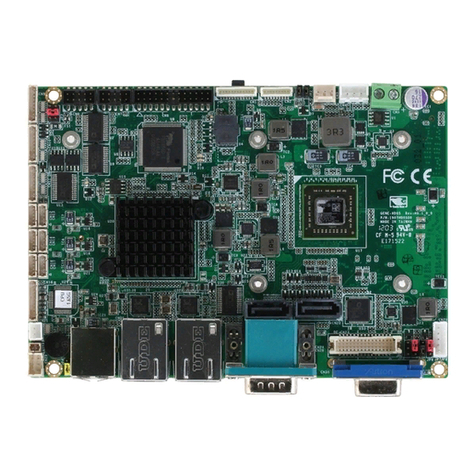
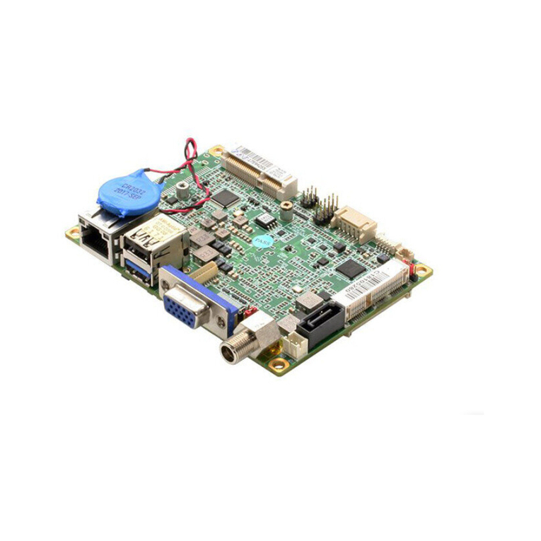
Aaeon FWB-7250 User manual

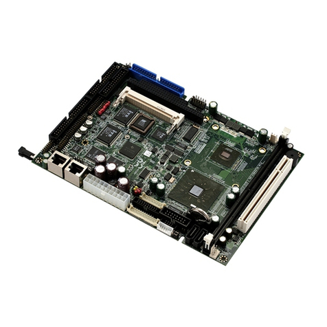
Networking Motherboard FWB- 7 250
FWB-7250
Networking Motherboard
CF SATA Socket
4 LAN Ports, 1 COM for Console
2 USB 2.0
1 MiniCard Slot with SIM
FWB-7250 Rev. A Manual 1st Ed.
July 3, 2015

Networking Motherboard FWB - 7250
Copyright Notice
This document is copyrighted, 2015. All rights are reserved. The
original manufacturer reserves the right to make improvements to the
products described in this manual at any time without notice.
No part of this manual may be reproduced, copied, translated, or
transmitted in any form or by any means without the prior written
permission of the original manufacturer. Information provided in this
manual is intended to be accurate and reliable. However, the original
manufacturer assumes no responsibility for its use, or for any in-
fringements upon the rights of third parties that may result from its
use.
The material in this document is for product information only and is
subject to change without notice. While reasonable efforts have been
made in the preparation of this document to assure its accuracy,
AAEON assumes no liabilities resulting from errors or omissions in
this document, or from the use of the information contained herein.
AAEON reserves the right to make changes in the product design
without notice to its users.
i

Networking Motherboard FWB - 7250
Acknowledgments
All other products’ name or trademarks are properties of their
respective owners.
Intel®and Atom™are trademarks of Intel®Corporation.
AMI is a trademark of American Megatrends Inc.
CompactFlash™ is a trademark of the Compact Flash
Association.
Microsoft Windows®is a registered trademark of Microsoft Corp.
All other product names or trademarks are properties of their
respective owners.
ii

Networking Motherboard FWB - 7250
Packing List
Before installation, please make sure that the following
materials have been shipped:
FWB-7250
CD-ROM for manual (in PDF format) and drivers
If any of these items should be missing or damaged, please
contact your distributor or sales representative immediately.
Note:
VGA Cable is an optional accessory. Please only purchase
cable with the following item number.
1700160150 VGA Cable (must be used with two
S21D305011 screws)
iii

Networking Motherboard FWB - 7250
China RoHS Requirements
产品中有毒有害物质或元素名称及含量
AAEON Main Board/ Daughter Board/ Backplane
部件名称
有毒有害物质或元素
铅
(Pb)
汞
(Hg)
镉
(Cd)
六价铬
(Cr(VI))
多溴联苯
(PBB)
多溴二苯醚
(PBDE)
印刷电路板
及其电子组件
×
○
○
○
○
○
外部信号
连接器及线材
×
○
○
○
○
○
O:表示该有毒有害物质在该部件所有均质材料中的含量均在
SJ/T 11363-2006
标准规定的限量要求以下。
X
:表示该有毒有害物质至少在该部件的某一均质材料中的含量超出
SJ/T 11363-2006
标准规定的限量要求。
备注:此产品所标示之环保使用期限,系指在一般正常使用状况下。
iv

Networking Motherboard FWB - 7250
Contents
Chapter 1 General Information
1.1 Introduction..........................................................1-2
1.2 Features ..............................................................1-3
1.3 Specifications ......................................................1-4
1.4 General System Information ...............................1-7
Chapter 2 Quick Installation Guide
2.1 Safety Precautions..............................................2-2
2.2 Jumpers and Connectors....................................2-3
2.3 Dimensions..........................................................2-5
2.4 List of Jumpers....................................................2-7
2.5 List of Connectors ...............................................2-8
2.6 Setting Jumpers ..................................................2-10
2.7 Auto Power Button (JP1).....................................2-11
2.8 CF Power Selection (CN13)................................2-11
2.9 CMOS Setting Selection (CN16).........................2-11
2.10 RTC Test Setting Selection (CN17)..................2-12
2.11 24-Pin ATX Power Connector (CN1) ................2-13
2.12 Power Button (CN2)..........................................2-14
2.13 SIM Card Socket (CN4) ....................................2-14
2.14 Compact Flash Socket (CN5) ...........................2-15
2.15 LCM Connector (CN6).......................................2-17
2.16 PS2 Keyboard/Mouse Pin Header (CN8)..........2-18
v

Networking Motherboard FWB - 7250
2.17 SATA Port Connector (CN9).............................2-19
2.18 SATA Power Connector (CN10 & CN14)..........2-19
2.19 USB2.0 Port 1 Pin Header (CN11)....................2-20
2.20 VGA Pin Header (CN12)...................................2-21
2.21 SATA Port Connector (CN15)...........................2-22
2.22 Mini PCI-E Slot (CN19) .....................................2-22
2.23 USB2.0 Type-A Connector (CN20)...................2-25
2.24 Console Port Connector (CN21) .......................2-25
2.25 Giga LAN Port Connector (CN22).....................2-26
2.26 Giga LAN Port Connector (CN23).....................2-27
2.27 Giga LAN Port Connector (CN24).....................2-27
2.28 Giga LAN Port Connector (CN25).....................2-28
2.29 COM Port Connector (COM1)...........................2-29
2.30 4-pin Fan Connector (CPU_FAN1)...................2-30
2.31 Front Panel Connector (FP1)............................2-31
2.32 Front Panel Connector (FP2)............................2-32
2.33 4-pin Fan Connector (SYS_FAN1)....................2-32
Chapter 3 AMI BIOS Setup
3.1 System Test and Initialization .............................3-2
3.2 AMI BIOS Setup..................................................3-3
Chapter 4 Driver Installation
4.1 Installation ...........................................................4-3
Appendix A Programming the Watchdog Timer
A.1 Watchdog Timer Initial Program .....................A-2
vi

Networking Motherboard FWB-7250
General
Information
Chapter
1
Chapter 1 General Information 1- 1

Networking Motherboard FWB-7250
1.1 Introduction
FWB-7250 adopts the Intel®Atom™ E3845/Celeron® J1900
Processors. The system memory features two 204-pin DDR3L
1333 SODIMM up to 8GB. It deploys four Gigabit Ethernet LAN
ports with two pairs LAN bypass function.
In addition, it offers flexible expansion with network products and
features one MiniCard slot with SIM socket, two USB 2.0 ports and
one RS-232 console port. The console port deploys console
re-direction that increases the network security via remote control.
Chapter 1 General Information 1- 2

Networking Motherboard FWB-7250
1.2 Features
4-LAN-port Networking Motherboard
Onboard Intel® Atom™ E3845/Celeron® J1900 SoC
204-pin DDR3L 1333 SODIMM x 2, up to 8GB
Intel® I210AT 10/100/1000Base-TX Ethernet Port x 4
MiniCard socket with SIM socket x 1
SATA 3.0 x 1, CompactFlash™ Socket x 1
RJ-45 console x 1
USB 2.0 x 2
Chapter 1 General Information 1- 3

Networking Motherboard FWB-7250
1.3 Specifications
System
Dimensions 170mm x 170mm (6.7” x 6.7”)
Processor
Intel® Celeron® J1900 2.0 GHz (Quad-core)
Intel® Atom™ E3845 1.91 GHz (Quad-core)
System Memory 204-pin DDR3L 1333
MHz SODIMM x 2, up to
8GB
Chipset -
Ethernet
Intel® I210-AT (Co-lay with Intel® I211-AT),
Gigabit Ethernet x 4 (2 pairs bypass, optional)
BIOS AMI BIOS
Serial ATA CompactFlash™ Socket x 1
SATA 3.0 connector x 1
Expansion Interface MiniCard socket x 1 w/ SIM card socket
Power Requirement ATX 100W PSU
Power Consumption Intel® Celeron® J1900 2.4GHz, DDR3L 1600
4GB - 0.26A@100VAC
Board Size 170mm x 170mm
Watchdog Timer 1~255 steps by software programming
MTBF (Hours) 110,000
OS Support Windows® 7 or above, Linux
Display
Chipset
Intel® Celeron® J1900
Intel® Atom™ E3845
Chapter 1 General Information 1- 4

Networking Motherboard FWB-7250
Graphic Engine Intel® HD Graphics
Resolution 2560 x 1600
Output Interface
Reserved pin header for graphic integrated
Processor
I/O
LAN Port RJ-45 x 4
Serial Port RJ-45 console x 1
Keyboard & Mouse Reserved pin header
USB USB 2.0 x 2
LED Power LED x 1, Status LED x
1, HDD active x
1, LAN LED x 8, Bypass LED x 1 (Optional)
Others
Power on/off x 1, software programmable reset
x 1
Environment
Operating
Temperature
0oC~60oC (32oF ~140oF)
Storage Temperature -40oC~85oC (-40oF ~185oF)
Operating Humidity 0%~90% relative humidity, non-condensing
Chapter 1 General Information 1- 5

Networking Motherboard
FWB - 7 250
Chapter 2 Quick Installation Guide 2-1
Quick
Installation
Guide
Chapter
2

Networking Motherboard
FWB - 7 250
Chapter 2 Quick Installation Guide 2-2
2.1 Safety Precautions
The installation is intended for technically qualified personnel who
have experience installing and configuring system boards.
The equipment can be installed in a restricted access location (RAL)
only.
A restricted access location is a site location for equipment where
the following criteria apply:
01. Access can only be gained by service persons or by users who
have been trained on the restrictions and the precautions for this
specific site.
02. Access is by means of at least one of the following, special tool,
lock and key, or other means of security, and is controlled by the
authority responsible for the location.
Safety Precautions:
Always completely disconnect the power cord
from your board whenever you are working on
it. Do not make connections while the power is
on, because a sudden rush of power can
damage sensitive electronic components.
Always ground yourself to remove any static
charge before touching the board. Modern
electronic devices are very sensitive to static
electric charges. Use a grounding wrist strap at
all times. Place all electronic components on a
static-dissipative surface or in a static-shielded
bag when they are not in the chassis

Networking Motherboard
FWB - 7 250
Chapter 2 Quick Installation Guide 2-3
2.2 Dimensions

Networking Motherboard
FWB - 7 250
Chapter 2 Quick Installation Guide 2-4

Networking Motherboard
FWB - 7 250
Chapter 2 Quick Installation Guide 2-5
2.2 Jumpers and Connectors

Networking Motherboard
FWB - 7 250
Chapter 2 Quick Installation Guide 2-6

Networking Motherboard
FWB - 7 250
Chapter 2 Quick Installation Guide 2-7
2.4 List of Jumpers
The board has a number of jumpers that allow you to configure your
system to suit your application.
The table below shows the function of each of the board's jumpers:
Label
Function
JP1
Auto Power Button
CN13
CF Power Selection
CN16
CMOS Setting Selection
CN17
RTC Test Setting Selection

Networking Motherboard
FWB - 7 250
Chapter 2 Quick Installation Guide 2-8
2.5 List of Connectors
The board has a number of connectors that allow you to configure
your system to suit your application. The table below shows the
function of each board's connectors:
Label
Function
CN1
24-Pin ATX Power Connector
CN2
Power Button
CN4
SIM Card Socket
CN5
CompactFlash Socket
CN6
LCM Connector
CN8
PS/2 Keyboard/Mouse Pin Header
CN9
SATA Port Connector
CN10
SATA Power Connector
CN11
USB2.0 Port 1 Pin Header
CN12
VGA Pin Header
CN14
SATA Power Connector
CN15
SATA Port Connector
CN19
Mini PCI-E Slot
CN20
USB2.0 Type-A Connector
CN21
Console Port Connector
CN22
Giga LAN Port Connector
CN23
Giga LAN Port Connector
CN24
Giga LAN Port Connector
CN25
Giga LAN Port Connector
BT1
Battery
Table of contents
Other Aaeon Motherboard manuals

Aaeon
Aaeon PCM-5894 User manual

Aaeon
Aaeon IMBA-Q77 User manual

Aaeon
Aaeon TKS-G21-CV05 User manual

Aaeon
Aaeon HSB-LN2I User manual

Aaeon
Aaeon EMB-Q170A User manual

Aaeon
Aaeon PCM-6890B Instruction Manual

Aaeon
Aaeon MPC-8890 User manual

Aaeon
Aaeon EMB-B75A User manual

Aaeon
Aaeon PICO-BT01 User manual

Aaeon
Aaeon EMB-Q170C User manual

Aaeon
Aaeon PCM-5890 User manual

Aaeon
Aaeon PCM-4894 User manual

Aaeon
Aaeon SBC-590 User manual

Aaeon
Aaeon PCM-QM77 User manual

Aaeon
Aaeon PCM-6894 User manual
Aaeon
Aaeon ECB-915A User manual

Aaeon
Aaeon PCM-6894 User manual

Aaeon
Aaeon MAX-C246A User manual

Aaeon
Aaeon SBC-676 User manual

Aaeon
Aaeon PICO-WHU4 User manual