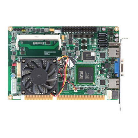
Aaeon SBC-670S User manual

SBC-670S
Full-size PCI/ISA
Pentium Pro CPU Card
with Ultra-Wide SCSI Interface
SBC-670
Full-size PCI/ISA
Pentium Pro CPU Card


Copyright Notice
This document is copyrighted 1997. All rights are reserved.
AAEON Technology Inc. reserves the right to make improvements
to the products described in this manual at any time without
notice.
No part of this manual may be reproduced, copied, translated or
transmitted in any form or by any means without the prior written
permission of the original manufacturer. Information provided in
this manual is intended to be accurate and reliable. However the
original manufacturer assumes no responsibility for its use, nor for
any infringements upon the rights of third parties which may result
from its use.
Acknowledgements
Adaptec and AHA are trademarks of Adaptec, Inc.
AMD is a trademark of Advanced Micro Devices, Inc.
Award is a trademark of Award Software International, Inc
Cyrix is a trademark of Cyrix Corporation.
IBM, PC/AT, PS/2 and VGA are trademarks of International
Business Machines Corporation.
Intel and Pentium are trademarks of Intel Corporation.
Microsoft Windows ®is a registered trademark of Microsoft Corp.
SMC is a treademark of Standard Microsystems Corporation.
All other product names or trademarks are properties of their
respective owners.
Part No: 2007670001 SBC-670/670S 2nd Edition
Printed in Taiwan Nov 1997

Packing list
Before you begin installing your card, please make sure that the
following materials have been shipped:
• 1 SBC-670S CPU card (or SBC-670 CPU Card)
• 1 6-pin mini-DIN dual outlet adapter for keyboard and PS/2
mouse
• 1 Hard disk drive (IDE) interface cable (40 pin)
• 1 Floppy disk drive interface cable (34 pin)
• 1 Parallel port adapter (26 pin) and PS/2 adapter (4 pin) kit
• 1 Accessory for SBC series screw & support
• 1 SCSI cable (50 pin) (For SBC-670S only)
• 1 Ultra wide SCSI cable (68pin) (For SBC-670S only)
• Two Driver Disketts; One for Dos, Windows 3.1; One for
Netware V3.1x/V4.0/V4.1x , OS/2, WinNT 3.5X, Win95 (For
SBC-670S only)
If any of these items are missing or damaged, contact your
distributor or sales representative immediately.

Contents
Chapter 1 General Information .....................1
Introduction............................................................................ 2
Features................................................................................... 3
Specifications.......................................................................... 4
Board layout............................................................................. 6
Card dimensions .................................................................... 7
Chapter 2 Hardware Configuration...............9
Jumpers and connectors...................................................... 10
Locating jumpers and connectors ...................................... 11
Setting jumpers .................................................................... 12
Safety precautions................................................................ 13
Installing the CPU................................................................ 14
Removing a CPU ................................................................... 14
Installing the CPU.................................................................. 14
CPU Frequency Select (JP4) ............................................... 15
CPU Bus Frequency Select (JP3)........................................ 15
CPU Clock Select (JP5) ....................................................... 16
ISA Bus Frequency Select (JP2) ......................................... 16
Flash Device Select (JP6)..................................................... 16
SCSI Terminator Select (JP1) ............................................ 17
Installing DRAM (SIMMs) ................................................. 18

Chapter 3 Connecting Peripherals .............19
IrDA Tx/Rx Header (IR CON) ........................................... 22
Power LED and Keylock (KEYLOCK)............................. 22
External Speaker (SPKER)................................................. 23
Hard Drive LED (IDE LED)............................................... 23
Reset Switch (RESET)......................................................... 23
Enhanced IDE (PRIMARY IDE, SECONDARY IDE) .... 24
Floppy Drive (FLOPPY DISK) .......................................... 24
Universal Serial Bus Connector (USB Connector) ........... 25
Parallel Port (PRINTER) .................................................... 25
Power Supply Connections.................................................. 26
6P Power Supply Connector (POWER CON)................... 26
4P Power Connector (CN1)................................................. 26
4P Fan Power Connector (CN2) ......................................... 27
Serial Ports (COM-A, COM-B).......................................... 27
Keyboard & PS/2 Mouse (KB/PS2 Mouse, KB CON, MS
CON) ..................................................................................... 28
Ultra-Wide SCSI Connector (WIDE-SCSI CON) ............ 29
SCSI-II Connector (SCSI HEADER INTERNAL)........... 31

Chapter 4 AMIBIOS Setup ...........................33
General information ............................................................ 34
Starting AMIBIOS setup ....................................................... 34
AMIBIOS main menu............................................................ 34
Standard CMOS Setup........................................................ 35
Advanced CMOS Setup....................................................... 36
Advanced Chipset Setup...................................................... 41
Power Management Setup .................................................. 42
PCI/Plug and Play Setup ..................................................... 45
Peripheral Setup .................................................................. 50
Change Supervisor Password ............................................. 52
Auto Configuration with Optimal Settings ....................... 52
Auto Configuration with Fail Safe Settings....................... 52
Save Settings and Exit ......................................................... 52
Exit Without Saving............................................................. 53
Chapter 5 SCSI Driver Installation..............55
Windows 95 Driver InstallationWindows 95 Driver Installation
Windows 95 Driver Installation ..................................
..................................
................. 5656
5656
56
Windows NTv4.0 Driver InstallationWindows NTv4.0 Driver Installation
Windows NTv4.0 Driver Installation ............................
............................
.............. 5858
5858
58
Windows NT v3.5x Driver InstallationWindows NT v3.5x Driver Installation
Windows NT v3.5x Driver Installation ........................
........................
............ 5959
5959
59
Netware V3.1x/V4.0/V4.1x Driver InstallationNetware V3.1x/V4.0/V4.1x Driver Installation
Netware V3.1x/V4.0/V4.1x Driver Installation ..............
..............
....... 6161
6161
61
OS/2 2.1x/Warp Driver InstallationOS/2 2.1x/Warp Driver Installation
OS/2 2.1x/Warp Driver Installation ............................
............................
.............. 6262
6262
62
Windows 3.1x Driver InstallationWindows 3.1x Driver Installation
Windows 3.1x Driver Installation ................................
................................
................ 6363
6363
63
Dos Driver InstallationDos Driver Installation
Dos Driver Installation ..............................................
..............................................
....................... 6363
6363
63
Appendix A: Programming the Watchdog Timer .. 65
Chapter 1 General Information 1
1
General
Information
This chapter gives background informa-
tion of SBC-670S.
Sections include:
• Card specifications
• Board layout
CHAPTER

2SBC-670S User's Manual
Introduction
The SBC-670S is an all-in-one, single board Pentium Pro computer
with an on-board, high performance Ultra-wide SCSI interface. It
packs all the functions of an industrial computer on a single, full-sized
card. The SBC-670S is fully PC/AT compatible, thus your software
will run without modifications.
The Ultra-wide SCSI interface speeds up the transfer rate to 40 MB/
sec and is capable of connecting 15 devices. An 8-bit PCI SCSI-II
interface is available as an option.
Other on-board features include a PCI Enhanced IDE interface, two
RS-232 ports with 16C550 UARTs, one bi-directional parallel port
and a floppy controller.
The SBC-670S' PCI Enhanced IDE interface support (through ATA
PIO) mode 3 and mode 4 hard disks, enabling data transfer rates in
excess of 11 MB/sec. Up to four IDE devices can be connected,
including hard disks, CD-ROM drives, tape backup drives and other
IDE devices.
If program execution is halted by a program bug or EMI, the watch-
dog timer will automatically reset the CPU or generate an interrupt.
This ensures reliability in unmanned or standalone systems.
The SBC-670S supports BEDO, EDO DRAM or Fast page DRAM for
system memory. It provides four 72-pin SIMM (Single In Line
Memory Module) sockets in two banks giving you the flexibility to
configure your system from 8 MB to 128 MB in the most economical
way.

Chapter 1 General Information 3
Features
qIntel Pentium Pro CPU 150~200MHZ, Socket 8 ZIF socket
qIntel 440 FX chipset
qSupports up to 128MB BEDO, EDO or Fast Page DRAM
qBuilt-in Ultra wide SCSI interface with 40MB/sec high transfer speed
and capable of connecting 15 devices
qSupport two USB ports
qFast PCI enhanced IDE controller supports four IDE drives(large hard
disks, CD-ROM, tape backup, etc.)
q32-bit PCI-bus, PICMG 2.0 standard
qPnP I/O address & IRQ selection
qTwo high-speed serial RS-232 ports (16C550 UARTs with 16-byte
FIFO)
qOne enhanced bi-directional parallel port supporting SPP/EPP/ECP.
qOn-board keyboard and PS/2 mouse connector
q9-bit GPIO interface
qGreen functions

4SBC-670S User's Manual
Specifications
CPU: Intel Pentium Pro CPU 150~200MHZ
Bus interface: PCI/ISA bus, PICMG 2.0 standard
Bus speed: ISA: 8~12 MHZ
PCI: 25~33 MHZ
Data bus: 64-bit
Processing ability: 64-bit
PCI SCSI-II interface: 8-bit SCSI-II interface
PCI Ultra-wide SCSI interface:16-bit Ultra-wide SCSI interface (40MB/sec)
PCI Enhanced IDE interface: Supports up to four IDE devices including
hard disk drives with PIO mode 3, 4
RAM memory: 8 MB to 128 MB in two banks of 72-pin SIMM
sockets, supporting BEDO, EDO, Fast page
DRAM
Shadow RAM memory: Supports system and video BIOS shadow
memory
Floppy disk drive interface: Supports up to two floppy disk drives, 5.25"
(360 KB and 1.2 MB) and/or 3.5" (720 KB,
1.44 MB and 2.88 MB)
Parallel port: One bi-directional parallel port. Supports
SPP/ECP/EPP mode
Serial ports: Two RS-232 ports (IrDA Tx/Rx header as an
option). Both use 16C550 UARTs with16-byte
FIFO.
GPIO port: 9-bit GPIO port supported
BIOS: AMI Flash BIOS supports DMI, PnP, Green
features; Adaptec 7880 Ultra-wide SCSI
RAID BIOS (For SBC-670S only)
Watchdog timer: The timeout interval is software selectable. (1
sec ~ 129 min., 7 sec/step)
DMA channels: 7
Interrupt levels: 15

Chapter 1 General Information 5
Keyboard/ mouse connector: 6-pin mini DIN connector supports standard
PC/AT keyboard and a PS/2 mouse.
USB: Supports 2 USB ports
Power supply voltage: +5V (4.75V to 5.25V), +12V power supply
Max. power requirement: +5V @ 12A
Operating temperature: 32° F to 140° F (0 to 60° C)
Board size: 13.3" (L) x 4.8"(W) (338mm x 122mm)
Board weight: 1.2 lbs (0.5Kg)

6SBC-670S User's Manual
Board layout
SBC-670 PENTIUM(R) PRO WITH SCSI CPU CARD Rev.A1
RS-232RS-232
SB82371SB
intel
Socket
EPM7032
ALTERA
BIOS
40MHZ
32Mhz
14.318
AIC-7880P
adaptec
PCIset
SB82441FX
intel
PCIset
SB82442FX
intel
FDC37C932
SMC

Chapter 1 General Information 7
Card dimensions
SBC- 590 Rev. A1
MADE INTAIWAN R.O.C.

8SBC-670S User's Manual

Chapter 2 Hardware Configuration 9
CHAPTER
2
Hardware
Configuration
This chapter gives background informa-
tion of the SBC-670S. It explains how to
configure the card and prepare it for
installation into your PC.
Sections include:
• Jumper settings
• Installing DRAM(SIMMs)

10 SBC-670S User's Manual
Jumpers and connectors
Connectors on the board link it to external devices such as hard
disk drives, a keyboard or floppy drives. In addition, the board has
a number of jumpers that allows you to configure your system to
suit your application. The table below lists the function of each of
the board jumpers and connectors.
Jumpers and connectors
Label Function
JP1 SCSI Terminator Select
JP2 ISA Bus Clock select (Reserved)
JP3 CPU Bus Frequency Select
JP4 CPU Frequency Select
JP5 CPU Clock Select
JP6 Flash Device Select
CN1 4P Power Connector
CN2 4P Fan Power Connector
KEYLOCK(CN3) Keyboard Lock
IDE LED(CN4) IDE device
SPKER(CN5) Speaker Connector
CN6 SCSI HEADER SCSI-II Connector
INTERNAL
CN7 PRIMARY IDE Primary IDE Connector
CN8 FLOPPY DISK Floppy Drive Connector
RESET(CN9) RESET Connector
WIDE-SCSI CON Ultra-Wide SCSI Connector
(CN10)
CN11 SECONDARY Secondary IDE Connector
IDE
CN12 PRINTER Printer Port
CN13,CN14 USB Connector
CN15 IrDA Tx/Rx Header
GPIO CON(CN16) GPIO Connector
MS CON(CN17) Mouse Connector
POWER CON(CN18) 6P Power Connector
COM-A(CN19) COM1 Connector
COM-B(CN20) COM2 Connector
KB CON(CN21) Keyboard Connector
KB/PS2 MOUSE Keyboard and PS/2 Mouse Connector
(CN22)

Chapter 2 Hardware Configuration 11
SBC-670 PENTIUM(R) PRO WITH SCSI CPU CARD Rev.A1
RS-232RS-232
SB82371SB
intel
Socket
EPM7032
ALTERA
BIOS
40MHZ
32Mhz
14.318
AIC-7880P
adaptec
PCIset
SB82441FX
intel
PCIset
SB82442FX
intel
FDC37C932
SMC
KB/PS2 MOUSE
KB CON
MS CON
JP4
SIMM
Locating jumpers and connectors
COM-A COM-B
FLOPPY DISK
PRINTER
CN15,14,13,JP2
PRIMARY IDE
SECONDARY IDE
WIDE-SCSI CON
SCSI CON
CN3,4,5,9,JP1
CN2
CN1
JP3
POWER CON
GPIO CON
JP5
JP6

12 SBC-670S User's Manual
Setting jumpers
You configure your card to match the needs of your application by
setting jumpers. A jumper is the simplest kind of electric switch. It
consists of two metal pins and a small metal clip (often protected
by a plastic cover) that slides over the pins to connect them. To
“close” a jumper you connect the pins with the clip. To “open” a
jumper you remove the clip. Sometimes a jumper will have three
pins, labeled 1, 2 and 3. In this case you would connect either pins
1 and 2 or 2 and 3.
The jumper settings are schematically depicted in this manual as
follows:
A pair of needle-nose pliers may be helpful when working with
jumpers.
If you have any doubts about the best hardware configuration for
your application, contact your local distributor or sales representa-
tive before you make any changes.
Generally, you simply need a standard cable to make most
connections.
13
2
Open Closed Closed 2-3
1 2 3

Chapter 2 Hardware Configuration 13
Safety precautions
Warning! Always completely disconnect the power cord
from your chassis whenever you are working on
it. Do not make connections while the power is
on, sensitive electronic components can be
damaged by the sudden rush of power. Only
experienced electronics personnel should open
the PC chassis.
Caution! Always ground yourself to remove any static
charge before touching the CPU card. Modern
electronic devices are very sensitive to static
electric charges. Use a grounding wrist strap at
all times. Place all electronic components on a
static-dissipative surface or in a static-shielded
bag when they are not in the chassis.
This manual suits for next models
1
Table of contents
Other Aaeon Motherboard manuals

Aaeon
Aaeon XTX-U15B User manual

Aaeon
Aaeon PCM-6890 User manual

Aaeon
Aaeon HSB-910I User manual

Aaeon
Aaeon EMB-A70M User manual

Aaeon
Aaeon PCM-6890 User manual

Aaeon
Aaeon GENE-HD05 User manual

Aaeon
Aaeon GENE-6315 User manual

Aaeon
Aaeon IMBM-H110A User manual

Aaeon
Aaeon PCM-6890B User manual

Aaeon
Aaeon PCM-6893 Instruction Manual

Aaeon
Aaeon EMB-945T User manual

Aaeon
Aaeon FSB-B75G User manual

Aaeon
Aaeon PCM-5894 User manual

Aaeon
Aaeon GENE-WHU6 User manual

Aaeon
Aaeon FSB-B75H User manual

Aaeon
Aaeon PICO-WHU4 User manual

Aaeon
Aaeon PCM-6897/L User manual

Aaeon
Aaeon PCM-4894 User manual

Aaeon
Aaeon Compact Board PCM-9452 User manual

Aaeon
Aaeon IMBA-H110A User manual