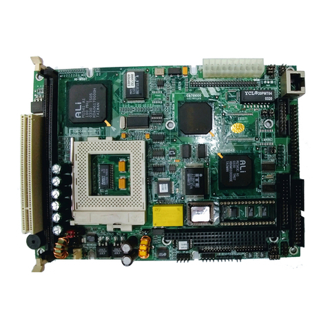
Aaeon SBC-357 User manual

SBC-357
Half-size All-in-one 386SX-40 CPU card

FCC STATEMENT
THIS DEVICE COMPLIES WITH PART 15 FCC RULES.
OPERATIONISSUBJECTTOTHEFOLLOWINGTWO
CONDITIONS:(1)THISDEVICEMAY NOT CAUSE HARM-
FULINTERFERENCE.(2)THISDEVICEMUSTACCEPT
ANYINTERFERENCERECEIVEDINCLUDINGINTERFER-
ENCETHATMAYCAUSEUNDESIRED OPERATION.
THIS EQUIPMENT HAS BEEN TESTED AND FOUND TO
COMPLY WITH THE LIMITS FOR A CLASS "A" DIGITAL
DEVICE, PURSUANT TO PART 15 OF THE FCC RULES.
THESE LIMITS ARE DESIGNED TO PROVIDE REASON-
ABLE PROTECTION AGAINTST HARMFUL INTERFER-
ENCE WHEN THE EQUIPMENT IS OPERATED IN A
COMMERCIAL ENVIRONMENT. THIS EQUIPMENT
GENERATES, USES, AND CAN RADIATE RADIO FRE-
QUENCY ENERGY AND , IF NOT INSTATLLED AND USED
IN ACCORDANCEWITH THE INSTRUCTION MANUAL,
MAY CAUSEHARMFUL INTERFERENCE TO RADIO
COMMUNICATIONS.OPERATION OF THIS EQUIPMENT
IN A RESIDENTIAL AREA IS LIKELY TO CAUSE HARM-
FUL INTERFERENCE IN WHICH CASE THE USER
WILL BE REQUIRED TO CORRECT THE INTERFER-
ENCE AT HIS OWN EXPENSE.

Copyright Notice
This document is copyrighted, 1998, by AAEON Technology Inc.
All rights are reserved. AAEON Technology Inc. reserves the
right to make improvements to the products described in this
manual at any time without notice.
No part of this manual may be reproduced, copied, translated, or
transmitted in any form or by any means without the prior written
permission of AAEON Technology Inc. Information provided in
this manual is intended to be accurate and reliable. However,
AAEON Technology Inc. assumes no responsibility for its use,
nor for any infringements upon the rights of third parties which
may result from its use.
Acknowledgements
ALI is a trademark of Acer Laboratories, Inc.
AMD is a trademark of Advanced Micro Devices, Inc.
AMI is a trademark of American Megatrends, Inc.
AutoCAD and AutoShade are trademarks of Autodesk, Inc.
CHIPS Logotype is a registered trademark; Chips 65550 is a
trademark of Chip and Technologies, Inc.
IBM, PC/AT, PS/2, and VGA are trademarks of International
Business Machines Corporation.
Lotus, 1-2-3, and Symphony are trademarks of Lotus Develop-
ment Corp.
Microsoft Windows®and MS-DOS are registered trademarks of
Microsoft Corp.
SMC is a trademark of Standard Microsystems Corporation.
TurboDLD Classic is a trademark of Panacea Inc.
UMC is a trademark of United Microelectronics Corporation.
WordPerfect is a trademark of WordPerfect Corporation.
VESA®is a registered trademark of Video Electronics Standards
Association.
All other product names or trademarks are properties of their
respective owners.
PartNo.200735701 SBC-357 A1.21st Edition
Printed in Taiwan March. 1999

Packing list
Before you begin installing your card, please make sure that the
following materials have been shipped:
• 1 supporting CD-ROM
• 1 SBC-357 CPUcard
• 1 Hard diskdrive(IDE)interface cable (40 pin)
• 1 Floppy disk drive interface cable (34 pin)
• 1 6-pin mini-DIN dual outlet adapter for keyboard and PS/2
mouse
• 1 parallel port adapter (26-25 pin) and dual outlet adapter kit
for COM port (10-9 pin) & (14-9 pin) adapter kit
• 2 serial adapter kit (9-10 Pin)
• 1 bag of screws and miscellaneous parts
If any of these items are missing or damaged, contact your distribu-
tor or sales representative immediately.
Notice
Dear Customer,
Thank you for purchasing the SBC-357 board. The user manual is
designed to help you to get the most out of the SBC-357, please
read it thoroughly before you install and use the board. This
product that you have purchased comes with a one-year limited
warranty; AAEON will not be responsible for any misuse of the
product. Therefore, we strongly urge that user first read the
manual before using the product.
To receive the lastest version of the user manual, please visit our
Web site at: Taiwan: www.aaeon.com.tw
U.S.A : www.aaeon.com

Contents
1 General Information ........................... 1
Introduction ............................................................................ 2
Features ................................................................................... 3
Specifications .......................................................................... 3
Board layout ........................................................................... 5
Carddimensions ..................................................................... 6
2 Installation ........................................... 7
Jumpersandconnectors ........................................................ 8
Locating jumpers and connectors......................................... 9
Setting jumpers ..................................................................... 10
Safetyprecautions .................................................................11
Installing DRAM(SIMMs) .................................................. 12
InstallingSIMMs .................................................................... 12
RemovingSIMMs................................................................... 12
IDEharddriveconnector(CN1) ......................................... 13
Floppy drive connector (CN2) ............................................. 15
Connecting thefloppy drive .................................................... 15
Parallel(printer)connector (CN3) ...................................... 16
Installingthe retainingbracket................................................. 16
Display connectors (CN10, CN4) ........................................ 17
Reserved IR connector (CN5).............................................. 19
Powerconnector(CN6)........................................................ 19
Serial port connectors (CN7, CN8, CN9, CN11)................ 20
KB and PS/2 mouse connector (CN12, CN14)................... 22
Keyboard lock function (CN13).......................................... 23
IDELED(JP1)...................................................................... 24
RS-232/422/485settingselect(JP2)..................................... 24
Buzzerorexternalspeaker (JP3)......................................... 25

LCD SHF/ASHF clock select (JP4)................................. 25
System management Interrupt (JP5) ............................... 26
Hardware Reset (JP6)........................................................ 26
COM3/COM4 IRQ select (JP7)...................................... 27
DiskOnChip installation (U15, JP8)................................. 27
LCD driving voltage select (JP9, JP10) ......................... 29
DiskOnChip socket (U15)................................................. 30
3 AMIBIOS Setup ................................... 31
General information ............................................................ 32
Starting AMIBIOS setup ........................................................32
AMIBIOS main menu.............................................................32
Using a mouse with AMIBIOS setup .....................................33
Using the keyboard with AMIBIOS setup..............................33
Standard CMOS setup ....................................................... 34
Advanced CMOS setup ..................................................... 36
Advanced chipset setup ..................................................... 42
Power management setup.................................................. 45
Peripheral Setup.................................................................. 48
Change supervisor password ............................................ 50
Auto configuration with optimal settings......................... 51
Auto configuration with fail safe settings ........................ 52
Save settings and exit......................................................... 53
Exit without saving ............................................................. 54

4 SVGA Setup ........................................ 55
Windows 3.1......................................................................... 56
Driver installation - Windows Setup ........................................56
DOS ....................................................................................... 57
SOFTWARE UTILITIES................................................... 59
The CHIPSCPL utility program..............................................59
Installing theutility ...................................................................59
How to use the utility ..............................................................59
A Watchdog Timer Demo Program . 61
Watchdog timer Demo Program ....................................... 62
B Installing PC/104 Modules ............... 67
Installing PC/104 modules................................................. 68


Chapter 1 General Information 1
CHAPTER
1
GeneraI
Information
This chapter provides background
information for the SBC-357.
Sections include:
· Card specifications
·Board layout

2SBC-357 User Manual
Introduction
The SBC-357 is an all-in-one single board 386 computer with an
onboard flat panel/CRT SVGA controller. It packs all the
functions of an industrial computer and its display capabilities
onto a single, half-size card. This means the SBC-357 is your
absolute best solution for embedded applications.
The onboard ISA-Bus, flat panel/CRT SVGA controller uses the
CHIPS 65545 chipset with up to 1 MB of video memory (512KB
onboard). It supports various LCD types including TFT, STN,
Normal, and EL.
The SBC-357 supports the optional M-Systems DiskOnChip
2000 which is a new generation of high performance single-chip
Flash Disk. It provides a Flash Disk (as a BIOS expansion) which
doesn't require any bus, slots, or connectors. It is also the optimal
solution for Single Board Computers because of its small size,
easy integration, plug-and-play functionality, and its low power
consumption. The DiskOnChip is available in capacities from
2MB to 72MB and fits in a standard 32-pin DIP socket.
The SBC-357 also features three high speed RS-232 serial ports,
and one RS-232/422/485 serial port with 16C550 UARTs, one
bidirectional SPP/EPP/ECP parallel port, and a floppy drive
controller, all onboard.
If program execution is halted by a program bug or EMI, the
board's watchdog timer can automatically reset the CPU or
generate an interrupt. This ensures reliability in unmanned or
standalone systems.
All configuration is done through software. A single Flash chip
holds the system BIOS, VGA BIOS, and the network boot ROM
image. This minimizes the number of chips and eases configura-
tion. You can change the display BIOS or install a boot ROM
simply by programming the Flash chip.
The SBC-357 supports 5 V EDO or FP DRAM. It also provides
two 72-pin SIMM (Single In-line Memory Module) sockets for
its onboard system DRAM. These sockets give you the flexibility
to configure your system up to 32 MB of DRAM using the most
economical combination of SIMMs.

Chapter 1 General Information 3
Features
•386SX-40 compatible CPU
•DiskOnChip (SSD) up to 72MB
• Can display both CRT and LCD simultaneously
•Connector for PC/104 module expansion
•Supports 4 serial ports: Three RS-232 ports and one RS-232/422/485
port
Specifications
CPU: Embedded in ALI M6117C Chipset Intel 80386SX-40 compatible
Data bus: 16-bit
BIOS: AMI Flash BIOS (Supports LBA mode HDD)
Chipset: ALI M6117C
Super I/O Chipset: ITE8663BF & ITE8661F
RAM memory: Up to 32MB.Use two 72-pin SIMM socket
Shadow RAM memory: Supports system and video BIOS shadow
memory
IDE hard disk drive interface: Supports up to one IDE (AT bus) hard
disk drives. BIOS auto-detect.
Floppy disk drive interface: Supports up to two floppy disk drive,
5.25”(360KB and 2MB) and /or 3.5”(720KB, 1.44MB and 2.88MB)
Bi-directional parallel port: One Bi-directional printer port (Config-
urable LPT1, LPT2, LPT3 or disable). Support SPP, ECP and EPP modes.
Serial ports: Three RS-232 serial ports and one RS-232/422/485 serial
port. Uses 16C550 UARTs with 16 byte FIFO. Supports speeds up to
115Kbps.Ports can be individually configured from COM1 to COM4 or
disabled.
Real-time clock/calendar: ALI chipset RTC (internal) and quartz
oscillator power by a lithium battery for 10 years of data retention.

4SBC-357 User Manual
DMA channel: 7
Interrupt levels: 15
KB/PS2 Mouse connector: 6 pin mini DIN connector supports a
standard PC/AT keyboard and mouse.
Flat panel VGA interface
Chipset: C&T 65545
Display memory: 512KB standard, 1MB option
Display type: Supports CRT and flat panel ( TFT , DSTN, mono and
EL)display, Can display both CRT and flat panel simultaneously.
Resolution: Option up to 1024 x 768 @ 256 colors.(1MB-display
memory). Standard 1024 x 768 @ 16 colors (512KB-display memory)
SSD interface
One 32-pin DIP socket supports M-systems DiskOnChip 2000 series,
memory capacity from 2MB to 72 MB.
Expansion Slot
PC/104 connector: 104-pin connector for a 16 -bit bus expansion.
Mechanical and environmental
Power supply voltage: +5V (4.75V to 5.25V)
Max. power requirements: +5V @ 2A
Operating temperature: 32 to 140 °F (0 to 60°C)
Board Size: 7.3” (L) X 4.8” (W) (185mm x 122mm)
Weight: 0.66 lb. (0.3Kg)

Chapter 1 General Information 5
Board layout SBC-357
ITE
8661F
CHIPS
F65545 B2
DiskOnChip
ITE
UM8663F
BAT
ALI
M6117C

6SBC-357 User Manual
Card dimensions
19.00 80.645
121.00
98.50
73.66
28.80
185.00
19.60

Chapter 2 Hardware Configuration 7
CHAPTER
2
Installation
This chapter describes how to set up the
SBC-357 hardware, including instruc-
tions on setting jumpers and connecting
peripherals, switches, and indicators. Be
sure to read all safety precautions before
you begin the installation procedure.

8SBC-357 User Manual
Jumpers and connectors
Connectors on the board link it to external devices such as hard
disk drives, a keyboard, or floppy drives. In addition, the board has
a number of jumpers that allows you to configure your system to
suit your application. The table below lists the function of each of
the board jumpers and connectors.
Name Function
CN1 IDE drive connector
CN2 Flopp drive connector
CN3 Parallel (printer) connector
CN4 LCD connector
CN5 IR connector
CN6 Power connector
CN7 RS-232/422/485 connector (COM2)
CN8 COM1 connector
CN9 COM3 connector
CN10 VGA connector
CN11 COM4 connector
CN12 Internal keyboard connector
CN13 Keyboard lock
CN14 KB/PS2 mouse connector
JP1 IDE LED
JP2 RS-232/422/485 select
JP3 Buzzer or external speaker
JP4 LCD SHF/ASHF clock select
JP5 Green function select (SMI)
JP6 Hardware reset
JP7 COM3/COM4 IRQ select
JP8 DOC address select
JP9 LCD driving voltage select
JP10 LCD voltage select (VGA CHIPSET)

Chapter 2 Hardware Configuration 9
Locating jumpers and connectors
ITE
8661F
CHIPS
F65545 B2
DiskOnChip
ITE
UM8663F
BAT
ALI
M6117C
CN3
CN2
JP5
JP6
CN14CN6 CN10
CN8
JP2
CN5
CN4
CN1
JP4
JP7
JP8
JP3
CN7 CN11CN9 CN12
CN13
JP1
JP9
JP10

10 SBC-357 User Manual
Setting jumpers
You configure your card to match the needs of your application by
setting jumpers. A jumper is the simplest kind of electric switch.
It consists of two metal pins and a small metal clip (often
protected by a plastic cover) that slides over the pins to connect
them. To “close” a jumper you connect the pins with the clip. To
“open” a jumper you remove the clip. Sometimes a jumper will
have three pins, labeled 1, 2, and 3. In this case you would
connect either pins 1 and 2 or 2 and 3.
The jumper settings are schematically depicted in this manual as
follows:
A pair of needle-nose pliers may be helpful when working with
jumpers.
If you have any doubts about the best hardware configuration for
your application, contact your local distributor or sales represen-
tative before you make any changes.
Generally, you simply need a standard cable to make most
connections.
13
2
Open Closed Closed 2-3
1 2 3

Chapter 2 Hardware Configuration 11
Safety precautions
Warning! Always completely disconnect the power cord
from your chassis whenever you are working on
it. Do not make connections while the power is
on because sensitive electronic components can
be damaged by the sudden rush of power. Only
experienced electronics personnel should open
the PC chassis.
Caution! Always ground yourself to remove any static
charge before touching the CPU card. Modern
electronic devices are very sensitive to static
electric charges. Use a grounding wrist strap at
all times. Place all electronic components on a
static-dissipative surface or in a static-shielded
bag when they are not in the chassis.

12 SBC-357 User Manual
Installing DRAM (SIMMs)
The SBC-357 CPU card provides two 72-pin SIMM (Single In-
line Memory Module) sockets and supports up to 32MB.
When installing SIMMs, make sure that Bank 1 is filled first.
* The SBC-357 CPU card supports single side F.P or EDO
DRAM module only.
Installing SIMMs
Note: that the modules can only fit into a socket one way.
1. Ensure that all power sources disconnected.
2. Slip the memory module into the socket at a moderate angle.
3. Push the module toward the vertical posts at both ends of the
socket until the module is upright and the retaining clips at
both ends of the module click into place. When positioned
correctly, the pins on top of the vertical posts should corre-
spond to the circular holes on the ends of the module.
4. Repeat steps 2 and 3 for each module you install.
Removing SIMMs
If you need to remove a SIMM, follow the procedures below:
1. Supporting the SIMM with a finger, use a pen or a similarly
shaped object and press one retaining clip straight down.
2. Repeat for the other side. When released, the retaining clips
will push the SIMM up and out of its upright position.
3. Carefully pull the SIMM out of the socket with your fingers.
4. Repeat the above steps for each module you remove.
Table of contents
Other Aaeon Motherboard manuals

Aaeon
Aaeon SBC-658 User manual

Aaeon
Aaeon IMBA-Q17A User manual

Aaeon
Aaeon PCM-4335 User manual

Aaeon
Aaeon MIX-Q370D2 User manual

Aaeon
Aaeon EMB-A70M User manual

Aaeon
Aaeon SBC-350A User manual

Aaeon
Aaeon PCM-6890B User manual

Aaeon
Aaeon MAX-C246A User manual

Aaeon
Aaeon EMB-Q77B User manual

Aaeon
Aaeon RICO-3399 User manual

Aaeon
Aaeon UPC-Plus User manual

Aaeon
Aaeon GENE-CV05 User manual

Aaeon
Aaeon EMB-830 User manual

Aaeon
Aaeon EMB-Q87A User manual

Aaeon
Aaeon EMB-9658T Mini-ITX User manual

Aaeon
Aaeon ATX-Q370A User manual

Aaeon
Aaeon EMB-Q87B User manual

Aaeon
Aaeon GENE-BT07 User manual

Aaeon
Aaeon TKS-G21-CV05 User manual

Aaeon
Aaeon IMBM-Q170A User manual