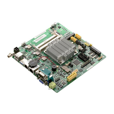
Aaeon PCM-4894 User manual

PCM-4894
All-in-One 486 single Board computer
with Flat Panel / CRT SVGA, Ethernet,
and 4 Serial Ports

Copyright Notice
This document is copyrighted, 1999, by AAEON Technology Inc.
All rights are reserved. AAEON Technology Inc. reserves the right
to make improvements to the products described in this manual at
any time without notice.
No part of this manual may be reproduced, copied, translated, or
transmitted in any form or by any means without the prior written
permission of AAEON Technology Inc. Information provided in
this manual is intended to be accurate and reliable. However,
AAEON Technology Inc. assumes no responsibility for its use, nor
for any infringements upon the rights of third parties which may
result from its use.
Acknowledgements
AMD is a trademark of Advanced Micro Devices, Inc.
AMI is a trademark of American Megatrends, Inc.
Award is a trademark of Award Software International, Inc.
CyrixisatrademarkofCyrixCorporation.
IBM, PC/AT, PS/2, and VGA are trademarks of International
Business Machines Corporation.
Intel and Pentium are trademarks of Intel Corporation.
Microsoft Windows®is a registered trademark of Microsoft Corp.
SMC is a trademark of Standard Microsystems Corporation.
RTL is atrademarkof Realtek Semi-Conductor Co., Ltd.
C&T is a trademark of Chips and Technologies, Inc.
UMC is a trademark of United Microelectronics Corporation.
ITE is a trademark of Integrated Technology Express, Inc.
SIS is a trademark of Silicon Integrated Systems Corp.
VIA is a trademark of VIA Technology, Inc.
All other product names or trademarks are properties of their
respective owners.
PartNo.2047489420 PCM-4894 Rev.A2.2 1st Edition
Prepared in Taiwan, April 1999

Packing list
Before you begin installing your card, please make sure that the
following materials have been shipped:
• 1 PCM-4894 Single board computer
• 1 Quick Installation Guide
• 1 CD-ROM contains the followings:
-- User's Manual (this manual in PDF file)
--VGA drivers and utilities
-- Ethernet drivers and utilities
-- Latest BIOS (as of this CD-ROM was made)
• PC/104 Module mounting support kit
The PCM-4894 require several cables for operation. You can make
them yourself or purchase an optional cable kit, PCM-10489-1 (Part
No:9969048900).
If any of these items are missing or damaged, contact your
distributor or sales representative immediately.
Notice
Dear Customer,
Thank you for purchasing the PCM-4894 board. The user's
manual is designed to help you to get the most out of the PCM-
4894, please read it thoroughly before you install and use the
board. The product that you have purchased comes with a one-
year limited warranty, but AAEON will not be responsible for any
misuse of the product. Therefore, we strongly urge that you first
read the manual before using the product.
To receive the lastest version of the user's manual, please visit our
Web site at:
http://www.aaeon.com

Contents
Chapter 1: General Information ................................ 1
Introduction ............................................................................ 2
Specifications .......................................................................... 3
Board layout ........................................................................... 6
Dimensions.............................................................................. 7
Chapter 2: Installation ................................................ 9
Jumpersand connectors ...................................................... 10
Locating jumpers and connectors........................................11
Setting jumpers ..................................................................... 12
Safetyprecautions ................................................................ 13
Installing DRAM(SIMMs) .................................................. 14
InstallingSIMMs .................................................................... 14
RemovingSIMMs................................................................... 14
Ethernetconnector (CN1) .................................................... 15
Serial ports connector (CN2)............................................... 16
COM 1-4 RS-232/422/485 serial ports (CN2) ........................ 16
Parallel port connector (CN3) ............................................. 17
IDEhard driveconnector (CN4) ......................................... 18
Floppy drive connector (CN5) ............................................. 20
Connecting the flopy drive ...................................................... 20
Power connector (CN6, CN17, CN18) ................................ 21
Keyboard and PS/2 mouse connectors (CN7).................... 22
Power LED and keylock (CN8) ........................................... 23
Reserved IR connector (CN9).............................................. 23
Digital I/O connector (CN10) .............................................. 24
LEDindicators/ Hardwarereset(CN13)............................ 25
Buzzeror external speaker(CN14) ..................................... 26
LCD connector (CN15) ........................................................ 27
VGA connectors (CN16) ...................................................... 28
COM3/4 RI function selection (JP1) .................................. 29

DOC address setting (JP2, 1-6) ....................................... 30
COM2 RS-232/422/485 select (JP2, 7-10) ..................... 30
LCD panel's voltage setting (JP4) ................................... 31
LCD SHF/ASHF clock select (JP5)................................. 31
DiskOnChip socket (U20)................................................. 32
Chapter 3: Award Setup ............................................. 33
System test and initialization ............................................. 34
Systemconfiguration verification ............................................34
Award BIOS setup .............................................................. 35
Entering setup..........................................................................35
Standard CMOS setup ....................................................... 36
BIOS features setup ........................................................... 38
CHIPSET features setup ................................................... 41
Power management setup.................................................. 42
PCI configuration setup ..................................................... 47
Load BIOS defaults / Load setup defaults ...................... 49
Chpater 4: Flat Panel/CRT Controller Display Drivers
and Utilities ............................................. 51
Software drivers .................................................................. 52
Hardware configuration ..........................................................52
Necessary prerequisites ..........................................................53
Before you begin .....................................................................53
Windows 95 .......................................................................... 54
Windows 3.1......................................................................... 55
Changing color schemes..........................................................56
Software utilities.................................................................. 57
The CHIPSDSP utility program..............................................57
The CHIPSCPL utility program..............................................59
Installing theutility ...................................................................59
How to use the utility ..............................................................59

Chapter 5: Ethernet Software Configuration ............ 61
Ethernet software configuration ....................................... 62
Appendix A: Watchdog Timer Demo Program ........... 63
How to program the WATCHDOG TIMER ................... 64
Demo program in C ............................................................ 65
Appendix B: Installing PC/104 Modules ....................... 67
Installing PC/104 modules................................................. 68
Appendix C: Optional Extras ....................................... 71
PCM-10489-1 Cable kit for PCM-4894.......................... 72

Chapter 1 General Information 1
CHAPTER
1
General
Information
This chapter provides background
information for the PCM-4894.
Sections include:
• Specifications
• Board layout
• Dimensions

2PCM-4894 User Manual
Introduction
The PCM-4894 is an all-in-one single board 486 computer with
an onboard flat panel/CRT SVGA controller and PCI Ether-
net interface. It offers all the functions of an industrial comput-
er and its display capabilities on a single board, but fits in the
space of a 5.25" floppy drive (only 5.75" x 8"). This means the
PCM-4894 is your absolute best solution for embedded applica-
tions.
The onboard PCI-bus, flat panel/CRT SVGA controller uses the
CHIPS 65550 chipset with up to 2 MB of video memory (on-
board 1MB). This chipset, used with the local PCI-bus, enables
32-bit graphic throughput at up to 33 MHz. Excellent for display-
intensive applications, it supports various LCD types including
TFT,STN,B/W,and EL.
The onboard Ethernet Realtek RTL 8029AS PCI bus Ethernet
controller supports remote boot ROM functions.
The PCM-4894 supports the M-Systems DiskOnChip 2000
(optional) which is a new generation of high performance single-
chip Flash Disk. It provides a Flash Disk (as a BIOS expansion)
which does not require any bus, slots, or connectors. It is also the
optimal solution for Single Board Computers because of its small
size, easy integration, plug-and-play functionality, and its low
power consumption. The DiskOnChip is available in capacities
from 2MB to 72MB and fits in a standard 32-pin DIP socket.
Another feature of the PCM-4894 is the inclusion of a high
speed, local bus IDE controller. This controller supports (through
ATA PIO) mode 3 and mode 4 hard disks, enabling data transfer
rates in excess of 11 MB/second. Up to two IDE devices can be
connected, including large hard disks, CD-ROM drives, tape
backup drives, or other IDE devices. The built-in, enhanced IDE
controller provides a 4-layer, 32-bit, posted write buffer and a 4-
layer, 32-bit read-prefetch buffer to boost IDE performance.

Chapter 1 General Information 3
Specifications
Standard SBC functions
CPU: AMD 5X86-P75 (486DX5-133) SQFP
BIOS:Award 128KB FLASH BIOS
Chipset: ALI 1487/1489
Super I/O Chipset: WINBOND83877TF
2nd Level Cache: On board 128KB 2nd level cache. Could be
upgraded to 512KB by factory.
RAM memory: 4MB to 128MB. Two 72-pin SIMM sockets on
board.
Enhanced IDE hard disk drive interface: Support up to two
hard disk drives. BIOS auto-detect. Supports PIO mode 4 and Bus
Master. 22 x 2 header, pitch 2.00mm with housing.
Floppy disk drive interface: Supports up to two floppy disk
drives, 5.25" (360KB and 1.2MB) and /or 3.5" (720KB, 1.44MB
and 2.88MB). 17 x 2 header, pitch 2.54mm with housing.
Multi-mode parallel port: Configured to LPT1, LPT2, LPT3 or
disabled. Supports SPP, ECP and EPP. 13 x 2 header, pitch
2.54mm with housing.
Serial ports: Three RS-232 and one RS-232/422/485 serial
ports. Ports can be configured as COM1, COM2, COM3, COM4
or disabled individually. Four 16C550 serial UARTs. 20 x 2
header, pitch 2.54mm with housing for RS-232 x 4.
Keyboard/mouse connector: 8 pin connector supports standard
PC/AT keyboard and PS/2 mouse.
Real Time Clock/Calendar: Dallas DS-12887A or equivalent,
powered by lithium battery for data retention of up to 10 years.

4PCM-4894 User Manual
Watchdog Timer: Can generate a system reset, IRQ15. Support
Windows 3.1, Windows 95. Software selectable timeout interval.
(1 ~ 255 sec., 1 sec./step)
DMA channels: 7
Interrupt levels: 15
Power connector: 4 pin 3.5” HDD male power connector.
Power management: I/O peripheral devices support power saving
and doze/standby/suspend modes. APM 1.1 compliant.
Flat panel VGA interface
Chipset: C&T65550
Display memory: 2MB on board.
Display type: Supports CRT and flat panel (TFT, DSTN, mono
and EL) display. Can display both CRT and flat panel simulta-
neously.
Resolution: Up to 1024x768@64K colors.
Ethernet interface
Chipset: Realtek RTL8029AS PCI Ethernet controller.
Ethernet interface: On board RJ-45 connector. Software drivers
optional. Supports boot ROM function.
SSD interface
One 32-pin DIP socket supports M-system DiskOnChip 2000
series, memory capacity from 2MB to 72MB.

Chapter 1 General Information 5
Digital I/O interface
4 TTL Digital Input bits & 4 Open Collector Digital Output bits.
(Port address : 294H, Bit : 0, 1, 2, 3)
Expansion Slots
PC/104 connector: 104 pin connector for a 16 bit bus expan-
sion. One PCI/ISA bus slot.
Mechanical and environmental
Power supply voltage: +5V (4.75V to 5.25V)
Max. power requirements: +5V @ 4A
Operating temperature: 32 to 140° F (0 to 60° C)
Board Size: 8”(L) x 5.75”(W) (203mm x 146mm)
Weight: 1.32 lb. (0.6 Kg)

6PCM-4894 User Manual
Board layout
20F001N
XILINX
XC9572
DiskOnChip
RTL8029AS
Winbond
Winbond
ALI
M1487A1
ALI
M1489 B1
CHIPS
F65550
AM486DX5
R T C

Chapter 1 General Information 7
Card dimensions
5.08 40.64 97.16
100.97
119.38
3.56
174.63
177.17
193.04
203.20
198.12
5.08
9.53
135.89
95.25
146.05
140.97

8PCM-4894 User Manual

Chapter 2 Installation 9
2
Installation
This chapter explains set up procedures
for the PCM-4894 hardware, including
instructions on setting jumpers and
connecting peripherals, switches and
indicators. Be sure to read all safety
precautions before you begin the installa-
tion procedure.
CHAPTER

10 PCM-4894 User Manual
Jumpers and connectors
Connectors on the board link it to external devices such as hard
disk drives, a keyboard, or floppy drives. In addition, the board has
a number of jumpers that allow you to configure your system to
suit your application.
The table below lists the function of each of the board jumpers and
connectors:
Jumpers and connectors
Label Function
CN1 Ethernet connector
CN2 Serial ports connector
CN3 Parallel port connector
CN4 HDD connector
CN5 FDD connector
CN6 Main power connector
CN7 Keyboard / PS2 mouse connector
CN8 Power LED / Keyboard lock
CN9 Reserved IR connector
CN10 Digital I/O connector
CN13 LED indicators / Hardware reset
CN14 External speaker connector
CN15 LCD connector
CN16 VGA connector
CN17 Auxiliary power connector
CN18 CPU fan power connector
JP1 COM3/4 RI function selection
JP2 DOC address / COM2 mode setting
JP4 LCD voltage selection
JP5 LCD SHF/ASHF clock selection
U20 DiskOnChip socket

Chapter 2 Installation 11
Locating jumpers and connectors
20F001N
XILINX
XC9572
DiskOnChip
RTL8029AS
Winbond
Winbond
ALI
M1487A1
ALI
M1489 B1
CHIPS
F65550
AM486DX5
R T C
CN5
CN6
CN12
CN13
CN14
CN15
JP5
JP4
CN16 CN18
PCI/ISA
RiserCard
Slot
JP3
JP2
CN1
CN4 CN2 CN3 JP1
CN7
CN17
CN10
U20
CN9
CN8

12 PCM-4894 User Manual
13
2
Open Closed Closed 2-3
1 2 3
Setting jumpers
You configure your card to match the needs of your application by
setting jumpers. A jumper is the simplest kind of electric switch.
It consists of two metal pins and a small metal clip (often
protected by a plastic cover) that slides over the pins to connect
them. To close a jumper you connect the pins with the clip. To
"open" a jumper you remove the clip. Sometimes a jumper will
have three pins, labeled 1, 2, and 3. In this case you would
connect either pins 1 and 2 or 2 and 3.
The jumper settings are schematically depicted in this manual as
follows:
A pair of needle-nose pliers may be helpful when working with
jumpers.
If you have any doubts about the best hardware configuration for
your application, contact your local distributor or sales represen-
tative before you make any changes.

Chapter 2 Installation 13
Safety precautions
Warning! Always completely disconnect the power cord
from your chassis whenever you are working on
it. Do not make connections while the power is
on because sensitive electronic components can
be damaged by the sudden rush of power. Only
experienced electronics personnel should open
the PC chassis.
Caution! Always ground yourself to remove any static
charge before touching the CPU card. Modern
electronic devices are very sensitive to static
electric charges. Use a grounding wrist strap at
all times. Place all electronic components on a
static-dissipative surface or in a static-shielded
bag when they are not in the chassis.

14 PCM-4894 User Manual
Installing DRAM (SIMMs)
The PCM-4894 CPU card provides two 72-pin SIMM (Single In-
line Memory Module) sockets and supports between 4MB and
64MB.
When installing SIMMs, make sure that Bank 1 is filled first.
Installing SIMMs
Note: that the modules can only fit into a socket one way.
1. Insert the memory module into the socket at a moderate angle.
2. Push the module toward the vertical posts at both ends of the
socket until the module is upright and the retaining clips at
both ends of the module click into place. When positioned
correctly, the pins on top of the vertical posts should corre-
spond to the circular holes on the ends of the module.
3. Repeat steps 1 and 2 for each module you install.
Removing SIMMs
If you need to remove a SIMM, follow the procedures below:
1. Supporting the SIMM with a finger, use a pen or a similarly
shaped object and press one retaining clip straight down.
2. Repeat for the other side. When released, the retaining clips
will push the SIMM up and out of its upright position.
3. Carefully pull the SIMM out of the socket with your fingers.
4. Repeat the above steps for each module you remove.
Table of contents
Other Aaeon Motherboard manuals

Aaeon
Aaeon PICO-BT01 User manual

Aaeon
Aaeon EMB-LN8T User manual

Aaeon
Aaeon PCM-LN05 Rev.B User manual

Aaeon
Aaeon MIX-KLUW1 User manual

Aaeon
Aaeon SBC-557 User manual

Aaeon
Aaeon EMB-A70M User manual

Aaeon
Aaeon MIX-Q370D1-A12 User manual

Aaeon
Aaeon GENE-QM77 User manual

Aaeon
Aaeon EMB-9658T Mini-ITX User manual

Aaeon
Aaeon HSB-835P User manual

Aaeon
Aaeon EMB-CV2 User manual

Aaeon
Aaeon PCM-4897 User manual

Aaeon
Aaeon EMB-BT1 User manual

Aaeon
Aaeon VIA Eden Series User manual

Aaeon
Aaeon SBC-659 User manual

Aaeon
Aaeon PCM-6890B Instruction Manual

Aaeon
Aaeon GENE-9310 User manual

Aaeon
Aaeon Raptor MicroATX User manual

Aaeon
Aaeon GENE-9655 User manual

Aaeon
Aaeon MIX-ALND1 User manual