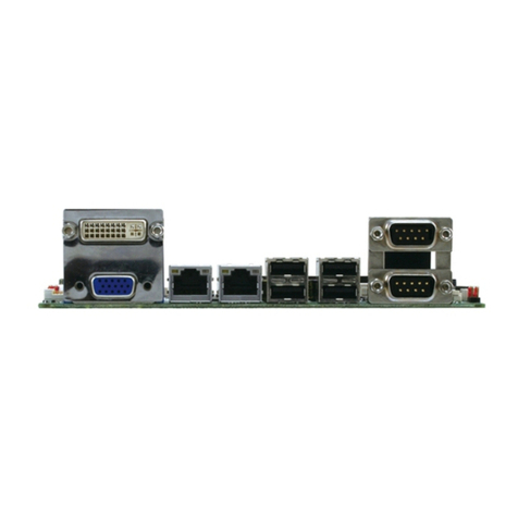
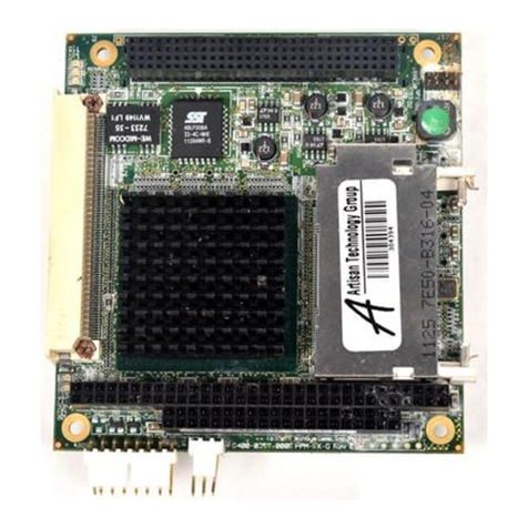
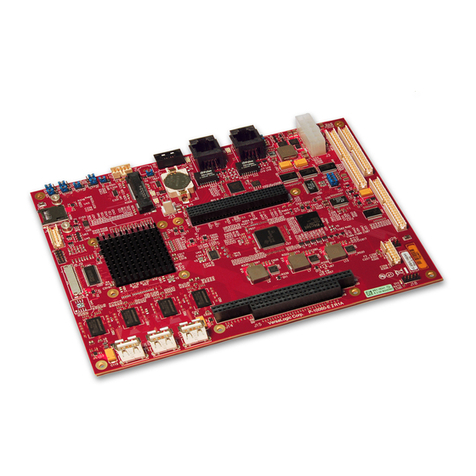
Aaeon PFM-CVS User manual

PC/104 Module PFM-CVS Rev. B
PFM-CVS Rev.B
Intel®Atom™ N2600 Processor
DDR3 1067MHz SODIMM
18-bit Single Channel LVDS LCD
4 USB2.0, 4 COM, 1 SATA, 1 mSATA
1 10/100/1000Base-TX Ethernet, PC/104+
Half/Full size Mini Card (Optional)
PFM-CVS Rev. B Manual 2nd Ed
December 2013

PC/104 Module PFM-CVS Rev. B
i
Copyright Notice
This document is copyrighted, 2013. All rights are reserved. The
original manufacturer reserves the right to make improvements to the
products described in this manual at any time without notice.
No part of this manual may be reproduced, copied, translated, or
transmitted in any form or by any means without the prior written
permission of the original manufacturer. Information provided in this
manual is intended to be accurate and reliable. However, the original
manufacturer assumes no responsibility for its use, or for any in-
fringements upon the rights of third parties that may result from its
use.
The material in this document is for product information only and is
subject to change without notice. While reasonable efforts have been
made in the preparation of this document to assure its accuracy,
AAEON assumes no liabilities resulting from errors or omissions in
this document, or from the use of the information contained herein.
AAEON reserves the right to make changes in the product design
without notice to its users.

PC/104 Module PFM-CVS Rev. B
ii
Acknowledgments
All other products’ name or trademarks are properties of their
respective owners.
Intel®and Atom™ are trademarks of Intel®Corporation.
Microsoft Windows®is a registered trademark of Microsoft Corp.
ITE is a trademark of Integrated Technology Express, Inc.
IBM, PC/AT, PS/2, and VGA are trademarks of International
Business Machines Corporation.
All other product names or trademarks are properties of their
respective owners.

PC/104 Module PFM-CVS Rev. B
iii
Packing List
Before you begin installing your card, please make sure that the
following materials have been shipped:
Jumper Cap
Product CD
PFM-CVS Rev. B with Heatsink
If any of these items are missing or damaged, please contact your
distributor or sales representative immediately.

PC/104 Module PFM-CVS Rev. B
iv
Contents
Chapter 1 General Information
1.1 Introduction................................................................... 1-2
1.2 Features....................................................................... 1-3
1.3 Specifications............................................................... 1-4
Chapter 2 Quick Installation Guide
2.1 Safety Precautions....................................................... 2-2
2.2 Location of Connectors and Jumpers .......................... 2-3
2.3 Mechanical Drawing..................................................... 2-5
2.4 List of Jumpers............................................................. 2-7
2.5 List of Connectors ........................................................ 2-8
2.6 Setting Jumpers ......................................................... 2-10
2.7 LVDS Voltage Selection (JP2)................................... 2-11
2.8 AT/ATX Selection and LVDS Backlight Control Voltage
Selection (JP3)................................................................. 2-11
2.9 COM2 +5V/Ring/+12V Selection (JP6)...................... 2-12
2.10 PCI-104 VIO Voltage Selection (JP7)...................... 2-12
2.11 Clear CMOS (JP8) ................................................... 2-12
2.12 PC/104 -5V/-12V Voltage Selection (JP11) Reserved
.......................................................................................... 2-13
2.13 Backlight Brightness Control Connector (CN2)........ 2-13
2.14 Internal LVDS Connector (CN3)............................... 2-14
2.15 SATA Power Connector (CN5) ................................ 2-15

PC/104 Module PFM-CVS Rev. B
v
2.16 PCI-104 Connector (CN6)........................................ 2-15
2.17 Front Panel Connector (CN7) .................................. 2-15
2.18 +12VSB Power Input Connector (CN9) ................... 2-16
2.19 PC/104/ ISA Connector (CN11)............................... 2-16
2.20 Digital I/O Connector (CN12)................................... 2-17
2.21 Mini PCI Express/mSATA Connector (CN14) (Optional)
.......................................................................................... 2-18
2.22 Battery Connector (BT1).......................................... 2-23
2.23 SATA Connector (SATA1) ....................................... 2-23
2.24 CRT Connector (VGA1)........................................... 2-24
2.25 COM1 RS-232 Connector (COM1).......................... 2-25
2.26 COM2 RS-232/422/485 Connector (COM2)............ 2-25
2.27 COM3 RS-232 Connector (COM3).......................... 2-27
2.28 COM4 RS-232 Connector (COM4).......................... 2-28
2.29 USB2.0 Connector (USB1) ...................................... 2-28
2.30 USB2.0 Connector (USB2) ...................................... 2-29
2.31 USB2.0 Connector (USB3) ...................................... 2-29
2.32 USB2.0 Connector (USB4) ...................................... 2-30
2.33 FAN Connector (FAN1) Reserved ........................... 2-30
2.34 LAN Connector (LAN1) ............................................ 2-31
2.35 DDR3 SODIMM Connector (DIMM1)....................... 2-31
2.36 Audio Connector (CN15).......................................... 2-32
2.37 PS2 Keyboard and Mouse Connector (CN18)......... 2-32
Chapter 3 AMI BIOS Setup
3.1 System Test and Initialization. ..................................... 3-2
PC/104 Module PFM-CVS Rev. B
vi
3.2 AMI BIOS Setup........................................................... 3-3
Chapter 4 Driver Installation
4.1 Installation.................................................................... 4-3
Appendix A Programming The Watchdog Timer
A.1 Watchdog Timer Initial Program...............................A-2
Appendix B I/O Information
B.1 I/O Address Map.......................................................B-2
B.2 1st MB Memory Address Map ...................................B-4
B.3 IRQ Mapping Chart...................................................B-5
B.4 DMA Channel Assignments......................................B-8
Appendix C Mating Connector
C.1 List of Mating Connectors and Cables......................C-2
Appendix D Electrical Specifications for I/O Ports
D.1 Electrical Specifications for I/O Ports .......................D-2
D.2 DIO Programming.....................................................D-3
D.3 Digital I/O Register....................................................D-4
D.4 Digital I/O Sample Program......................................D-5

PC/104 Module PFM-CVS Rev. B
Chapter 1 General Information 1- 1
Chapter
General
1
Information

PC/104 Module PFM-CVS Rev. B
1.1 Introduction
AAEON Technology, a leading company in embedded boards
manufacturing with a full range of PC/104 Modules, launches a brand
new PC/104 CPU Module-PFM-CVS Rev. B. Its compact size and
rich functionality ensures the most cost effective and compatible
module to coincide with your existing system planning devices.
PFM-CVS Rev. B adopts an Intel®Atom™ N2600 Dual Core 1.6 GHz
Processor with the latest Intel technology. Although PFM-CVS Rev.
B is a small board, it offers the full functions for customers demand.
The chipset of PFM-CVS Rev. B deploys Intel®Atom™ N2600 and
NM10 that make this board achieve high performance. It features
one 10/100/1000Base-TX Ethernet port, four USB 2.0 ports, four COM
ports. In addition, the PFM-CVS Rev. B equips PC/104+ socket and
Half/Full size mSATA/ Mini Card (optional) for flexible expansions.
Chapter 1 General Information 1- 2

PC/104 Module PFM-CVS Rev. B
1.2 Features
zFanless Intel®Atom™ N2600 Dual Core 1.6 GHz
Processor
zIntel®Atom™ N2600 + NM10
z204-pin DDR3 1067 MHz SODIMM x 1, Max. 2 GB
z10/100/1000Base-TX Ethernet x 1
zCRT, 18-bit Single Channel LVDS LCD
zSATA 3.0 Gb/s x 1
z2CH HD Audio
zUSB2.0 x 4, COM x 4
zPC/104+ Standard Form Factor Legacy ISASupport. (w/IO
Mode), mSATA / Mini Card (Optional) (Half/Full Size
support)
z+12V Only Operation
Chapter 1 General Information 1 - 3

PC/104 Module PFM-CVS Rev. B
1.3 Specifications
System
zForm Factor PC/104
zProcessor Intel®Atom™ N2600 1.6 GHz
processor
zSystem Memory 204-pin DDR3 1067 MHz
SODIMM x 1, Max. 2 GB
zChipset Intel
®Atom™ N2600+ NM10
zI/O Chipset Fintech F81866D
zEthernet Intel 82583V for
10/100/1000Base-TX, RJ-45x 1
zBIOS AMI BIOS – 32MB ROM
zWake on LAN Yes
zWatchdog Timer Generates a time-out system
reset
zH/W Status Monitoring Supports power supply voltage
and temperature monitoring
zExpansion Interface PC/104+, mSATA/ Mini Card(
Half/Full size supported)
zPower Requirement +12V, AT (Default) /ATX
zBattery Lithium battery
zBoard Size 3.78” x 4.05” (96mm x 103mm)
zGross Weight 0.35 lb (0.16 Kg)
Chapter 1 General Information 1- 4

PC/104 Module PFM-CVS Rev. B
zOperating Temperature 32°F~ 140°F (0°C ~ 60°C)
WiTAS 2 : -40°F~ 185°F
(-40°C~85°C)
(PFM-CVSW2-B10)
zStorage Temperature 32ºF ~ 140ºF (0ºC ~ 60ºC)
zOperating Humidity 0%~90% relative humidity,
non-condensing
Display: Supports CRT/LCD simultaneous/ dual view displays
zChipset Intel®Atom™ N2600 processor
integrated
zResolutions Up to 1920x1200 for VGA;
Up to 1366x768 for LVDS
zLCD Interface 18-bit Single Channel LVDS
I/O
zStorage SATA 3.0 Gb/s x 1, mSATA x 1
zSerial Port RS-232 x 3,
RS-232/422/485 x 1
zUniversal Serial Bus USB 2.0 x 4
zDigital I/O 8-bit Digital I/O (Programmable)
zAudio Line-in, Line-out, Mic-in
Note: For PFM-CVSW2-B10, we recommend to add a thermal
module on DDR3 memory and the recommended thermal pad of the
Chapter 1 General Information 1 - 5

PC/104 Module PFM-CVS Rev. B
thermal module is “SARCON® XR-HL” (1.2 W/m-K) or better.
Chapter 1 General Information 1- 6

PC/104 Module PFM-CVS Rev. B
Limitation Notice on ISAInterface Support
According to the information from Intel for Atom™ Processor design,
Intel®Atom™ Processor D2000 and N2000 Series do NOT support
ISA expansion area (C_0000h-D_FFFFh). This area always maps to
system DRAM. The illustration is as below for reference.
Document source: Intel®Atom™ Processor D2000 and N2000 Series
page 34 mentions that is External Design Specification – Volume 2 of 2.
(449931_449931_CDV_EDS_Vol2_Rev1p6)
Chapter 1 General Information 1 - 7

PC/104 Module PFM-CVS Rev. B
Chapter2QuickInstallationGuide2-1
Quick
Installation
Chapter
2
Guide

PC/104 Module PFM-CVS Rev. B
Chapter 2 Quick Installation Guide 2-2
2.1 Safety Precautions
Always completely disconnect the power cord
from your board whenever you are working on
it. Do not make connections while the power is
on, because a sudden rush of power can
damage sensitive electronic components.
Always ground yourself to remove any static
charge before touching the board. Modern
electronic devices are very sensitive to static
electric charges. Use a grounding wrist strap at
all times. Place all electronic components on a
static-dissipative surface or in a static-shielded
bag when they are not in the chassis

PC/104 Module PFM-CVS Rev. B
Chapter2QuickInstallationGuide2-3
2.2 Location of Connectors and Jumpers
Component Side

PC/104 Module PFM-CVS Rev. B
Solder Side
Chapter 2 Quick Installation Guide 2-4

PC/104 Module PFM-CVS Rev. B
Chapter2QuickInstallationGuide2-5
2.3 Mechanical Drawing
Component Side

PC/104 Module PFM-CVS Rev. B
Chapter 2 Quick Installation Guide 2-6
Solder Side
Other manuals for PFM-CVS
1
Table of contents
Other Aaeon Single Board Computer manuals

Aaeon
Aaeon PCM-4890 User manual

Aaeon
Aaeon EPIC-QM57 User manual

Aaeon
Aaeon PICO-EHL4-A11 User manual

Aaeon
Aaeon HSB-CV1P User manual

Aaeon
Aaeon UP User manual

Aaeon
Aaeon PFM-CVS User manual

Aaeon
Aaeon GENE-TGU6 User manual

Aaeon
Aaeon BOXER-RK88-0001 User manual

Aaeon
Aaeon UP-CHCR1 User manual

Aaeon
Aaeon EPIC-BDU7 User manual
Popular Single Board Computer manuals by other brands

IEI Technology
IEI Technology KINO-EHL-J6412 Quick installation guide

ADLINK Technology
ADLINK Technology cPCI-6880 Series user manual

iWave
iWave iW-RainboW-G25S Hardware user's guide

Advantech
Advantech PCA-6012 Startup manual

Nexcom
Nexcom Peak 703P Series user manual

MicroSys
MicroSys miriac SBC-T1024 user manual