AAF Flanders AstroPure 500-IR User manual

AstroPure™
Portable Air Purification System
INSTALLATION, OPERATION, AND MAINTENANCE MANUAL

1
TABLE OF CONTENTS:
Introduction and Precautions............................................................................................................. 2
Precautions & Warnings ................................................................................................................... 2
Important Safety Instructions ........................................................................................................... 3
Intended Use..................................................................................................................................... 3
Product Overview & Installation Instructions .................................................................................. 4
Platform Overview............................................................................................................................. 4
Specifications.................................................................................................................................... 5
Shipping and Receiving.................................................................................................................... 5
Unpacking ......................................................................................................................................... 6
Installation Instructions ..................................................................................................................... 7
Quick Start Guide & Operation........................................................................................................... 8
Quick Start Guide ............................................................................................................................. 8
Air Flow Calculation .......................................................................................................................... 9
EC Motor Speed Adjustment ......................................................................................................... 10
Operating Instructions .................................................................................................................... 10
Operating Environmental Conditions....................................................................................... 10
Internal Fuse.............................................................................................................................. 10
Internal Kill Switch..................................................................................................................... 10
Wiring Diagram.................................................................................................................................11
Maintenance & Service ...................................................................................................................... 12
Filter Replacement .......................................................................................................................... 12
Replacement Parts ......................................................................................................................... 13
Control Panel ....................................................................................................................................... 14
Overview and Main Screen ............................................................................................................ 14
Filter’s Pressure Drop and Particulate Matter Counting Screen................................................... 15
Decontamination and Other Set-up Screen .................................................................................. 15
Operational Timer / Programming Screen..................................................................................... 16
Trouble Shooting Guide ......................................................................................................................17
Warranty ............................................................................................................................................... 18
Manual Revision History.................................................................................................................... 19
Contacting AAF Flanders .................................................................................................................. 20

2
INTRODUCTION AND PRECAUTIONS
Introduction
This document contains the information necessary to receive, assemble, install, operate, and
maintain AAF Flanders AstroPureTM Air Purification System properly. The purchaser, installer, and
operator of the filtration system MUST read and comply with this document in its entirety. Failure to
comply with the requirements of this document may result in serious injury, potentially death, and
void the product warranty.
These instructions are specific to the AAF Flanders AstroPure Air Purification System. All ancillary
tasks including, but not limited to, electrical and mechanical work, equipment handling, and safety
procedures must be performed in accordance with industry-accepted practice and all relevant local,
state, and federal government codes, laws, and policies.
Before proceeding with installation, operation, or maintenance, review this manual in its entirety and
all safety procedures with your company’s safety personnel.
Precautions & Warnings
• Equipment must be properly transported and handled, as improper transport and/or handling can
result in damage and/or blemishes.
• Deliveries are to be immediately inspected in the presence of the freight carrier to ensure
equipment is delivered in full and damage-free.
• The installation site and environmental conditions must be suitable for equipment installation and
operation.

3
Important Safety Instructions
1. READ AND SAVE THESE INSTRUCTIONS
2. WARNING – To reduce the risk of fire, electrical shock, or injury to persons, observe the
following:
a. Equipment must be installed and operated with filters specified in this document. Other
filters cannot be substituted, as this will impact the performance of the equipment.
b. Use this equipment in the manner intended by the manufacturer. If you have questions,
contact the manufacturer:
For Technical or Application Questions:
Email: AstroPure@aafintl.com
c. Before servicing or cleaning equipment, switch power off at the back of the equipment
and unplug the power cable to prevent power from being switched on accidentally.
d. Power cord should never be exposed to water, heat, or sharp objects. Check power cord
before use. Never operate with a damaged power cord; replace immediately.
e. Equipment should always be operated indoors in an HVAC-conditioned space and never
be exposed to water.
f. Installation work and electrical wiring must be done by a qualified person(s) in accordance
with all applicable codes and standards, including fire-rated construction.
g. Follow the heating equipment manufacturer’s guideline and safety standards, such as
those published by the National Fire Protection Association (NFPA); the American Society
for Heating, Refrigeration, and Air Conditioning Engineers (ASHRAE); and the local code
authorities.
h. When cutting or drilling into wall or ceiling, do not damage electrical wiring or other hidden
utilities.
i. Ducted fans must always be vented to the outdoors.
3. CAUTION –Automatically operated device. To reduce the risk of injury, disconnect
power cord from power supply before servicing.
4. WARNING –Risk of electrical shock. Can cause injury or death. Disconnect all remote
electrical power before servicing. If connected to a circuit protector device by fuses,
use time-delay fuses for this appliance.
Intended Use
The AAF Flanders AstroPureTM Air Purification System is designed to increase indoor air quality (IAQ)
and reduce the risk of airborne infection within classrooms, clinics, office buildings, restaurants, and
healthcare facilities. This is accomplished by recirculating conditioned air and removing contaminants
from the space. Contaminants removed may include dust, pollen, mold, bacteria, and viruses.
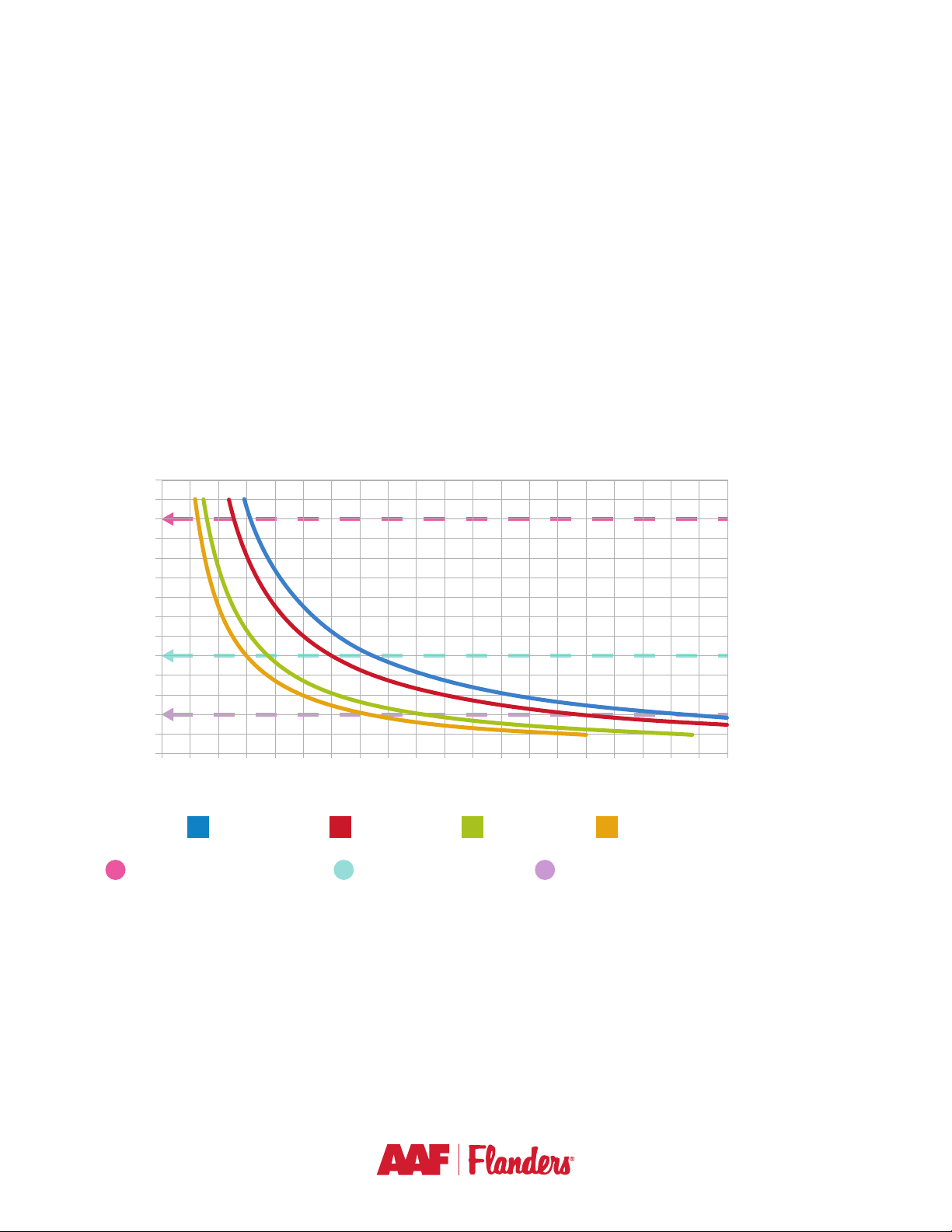
AstroPure Principle of Operation
The AAF Flanders AstroPure Air Purification System is not intended for use as a dust/smoke
extraction system for remediation of a “dirty” environment. Use as such will result in significantly
reduced performance and may void warranty.
INTRODUCTION AND PRECAUTIONS (CONT’D)

4
PRODUCT OVERVIEW & INSTALLATION INSTRUCTIONS
Platform Overview
The AAF Flanders AstroPureTM Air Purification platform includes two capacity ranges: a 0-500CFM
and 500-1000CFM unit.
Part Number Model Number Additional Description
393-500-100 AstroPure 500 IR Indoor Portable Unit – Air Recirculation – 0-500CFM
393-500-200 AstroPure 500 IE Indoor Portable Unit – Air Exhaust – 0-500CFM
393-500-300 AstroPure 1000 IR Indoor Portable Unit – Air Recirculation – 0-1000CFM
393-500-400 AstroPure 1000 IE Indoor Portable Unit – Air Exhaust – 0-1000CFM
Integrated PM Sensor
High-capacity
MERV 11 Prelter
Energy Savings–
Electronically Commutated
(EC) Motor
Robust Construction
with Internal Noise
Attenuators
High-capacity HEPA
Membrane Filter
99.99% @ 0.3 Micron
• Two-stage filtration technology
– MERV 11 prefilter & HEPA filter – 99.99%
capture efficiency (0.3 micron)
• EC motor technology for efficient operation of
two different capacity ranges
– 0-500CFM
– 500-1000CFM
• Preinstalled locking caster wheels and filters
• No assembly required
• 115V/120V operation for plug-&-play installation
• Control panel with multiple functions
• Housing 18-gauge cabinet construction with
powder coat finish
• Internally fuse protected
• ETL listed
• One-year limited warranty
Features

5
Product Model
AstroPure 500-IR
Internal portable unit -
recirculation mode
AstroPure 500-IE
Internal portable unit -
exhaust air mode
AstroPure 1000-IR
Internal portable unit -
recirculation mode
AstroPure 1000-IE
Internal portable unit -
exhaust air mode
Non-ducted Ducted (12" collar) Non-ducted Ducted (12" collar)
Voltage Hz 120V-60Hz 120V-60Hz 120V-60Hz 120V - 60Hz
Power W250W 250W 750W 750W
Max Airow Rate CFM 500 500 1000 1000
Operational
Airow Rate CFM 400 400 800 800
Noise Level -
Operational Point Db(A) <44 <44 <56 <56
Dimensions HxWxD 51 3/8"x 22 7/8"x 24" 51 3/8"x 22 7/8"x 24" 51 3/8"x 22 7/8"x 24" 51 3/8"x 22 7/8"x 24"
Weight Lbs 220 220 230 230
Pre Filter MERV 11 16x16x4" 16x16x4" 16x16x4" 16x16x4"
HEPA Filter 99.99% 18x18x12" 18x18x12" 18x18x12" 18x18x12"
Motor Type EC Variable Speed - EC Variable Speed - EC Variable Speed - EC Variable Speed - EC
Motor Power HP 0.33 0.33 1 1
Max Current Draw A 7 7 15 15
Blower Type Impeller Forward Curved Impeller Forward Curved Impeller Forward Curved Impeller Forward Curved Impeller
Sensor Embedded YES YES YES YES
Control Interface Programmable HMI Programmable HMI Programmable HMI Programmable HMI
Specifications
Shipping and Receiving
Deliveries are to be immediately checked in the presence of the carrier as being intact and complete.
Equipment must be properly transported. Improper transport can lead to:
• Internal component disconnection
• Metallic structure deformation
• Broken casters
• Sensors and control panel (HMI) damage
Pallet dimension (approx):
27" x 26" x 53" + 4.5” wood pallet
72 units per trailer aprox.
(under revision and confirmation)
PRODUCT OVERVIEW & INSTALLATION INSTRUCTIONS (CONT’D)

6
Unpacking
3. Ensure when the unit is removed from the package that it is placed upon smooth, level, and stable
ground.
4. Inspect for concealed damage and any hardware that may have become loose in transit.
5. Inspect for further damage that may adversely affect the equipment.
A B C
1. Carefully remove the equipment from the shipping carton and inspect for any damage that may
have occurred during transportation. Two workers at minimum are required to lift the unit from
the container.
2. Remove unit from shipping carton.
Items Shipped Per Carton:
1. Equipment with preinstalled filtration technology
2. Installation, Operation, & Maintenance manual
3. Quick Start Guide
See Maintenance and Service section for a list of spare parts sold separately.
PRODUCT OVERVIEW & INSTALLATION INSTRUCTIONS (CONT’D)

7
Installation Instructions
CAUTION:
• All electrical connections must be made by qualified, trained personnel only in accordance with all
local, state, and national electrical codes and federal regulations.
• Install power cord and make electrical connection to appropriate 115/120V 60Hz outlet. Install in
accordance with all local, state, and nation electrical codes.
– Important Note: The equipment is “plug and play” and requires minimum conditions for
normal operation. A standard 9 ft (3m) power cord is pre-fixed into the unit.
• Plug the power cord into a suitable 115V/120V grounded electrical receptacle on an electrically
protected circuit.
• See Quick Start Guide & Operation section of this document for instructions on unit start-up and
operation.
1. Read and observe all safety instructions included in this document for safe installation & operation.
2. Determine where the AAF Flanders AstroPureTM Air Purification System is to be installed.
3. Remove the equipment from the packaging as described in the Unpacking section of this
document.
4. Ensure when the equipment is removed from the package that it is placed upon smooth, level,
and stable ground.
5. Unlock the caster wheels.
a. AAF Flanders AstroPure Air Purification Systems come with pre-installed caster wheels and
filters. There is no required assembly of these items.
6. Carefully move the unit to the desired location of service.
a. When moving the unit: Make sure the path is free of obstacles, make sure the wheels are
unlocked, place hands around the center of the unit, and move slowly.
WARNING:
Risk of fall over during movement
• Use extreme caution when moving the unit to its final location.
• Move the unit very slowly and make sure the back wheels are not blocked (release the brake).
• After placing the unit in the final location, make sure that all wheels are pointed in the front of the
unit AND push the brake bracket in the back wheels.
• NEVER place any object on the unit.
• NEVER insert your fingers or any other object into the unit.
• NEVER obstruct the air inlet (bottom front) and the air outlet (top) of the unit.
READ and follow instruction manual before starting the unit.
PRODUCT OVERVIEW & INSTALLATION INSTRUCTIONS (CONT’D)

8
Quick Start Guide
1. Read and observe all safety and installation instructions provided in the Introduction and
Installation Instructions section of this document.
2. After completion of installation, turn on the power switch located on the back of the unit.
3. The unit is preset to 60% of maximum power.
a. If the installer would like to adjust the CFM settings, see the EC Motor Speed Adjustment
Section for details on how to make adjustments.
4. When the power cord is plugged into a wall receptacle and the power switch is ON, the control
panel (HMI) will sound an audible confirmation and illuminate.
5. The system starts with the fan in OFF position. To turn it ON, it is necessary to press the power
button (RED).
a. The EC motor may require time to get to full operating speed (RPM). If the installer does not
immediately detect the motor running upon turning the unit on, please allow 10 seconds for
the EC motor to get to full operating RPM.
QUICK START GUIDE & OPERATION
Important note: For additional information about
controlling and set-up, see the Control Panel section.

9
Air Flow Calculation
Per ASHRAE guidelines and other relevant guidelines, the feet coverage of each unit can be
calculated using the following example:
CFM = (Ceiling Height) x (Room Square Footage) x (ACH) x (1hr/60min)
As an example, if the unit is installed in a 35’ x 40’ room with 10’ ceilings, and the user would like
to achieve the minimum recommended 2 ACH, then the recommended CFM for the unit would be:
CFM = (10’) x (35’x40’) x (2ACH) x (1hr/60min) = 466CFM
NOTE: ASHRAE recommends a minimum of 2 ACH for re-opening schools, for example.
The following graph represents the feet coverage for each AstroPureTM unit considering four different
operational points:
Room Size Calculation (8ft Ceiling Height)
14
13
12
11
10
9
8
7
6
5
4
3
2
1
0
0200 400 600 800 1000 1200 1400 1600 1800 2000 2200 2400 2600 2800 3000 3200 3400 3600 3800 4000
Air Changes Per Hour (ACH)
Room Area (ft2)
Room Area X Air Changes Per Hour (1 AstroPure™Unit)
1000 CFM 800 CFM 500 CFM 400 CFM
ASHRAE/REHVA(1,2)
Recommendation for
Healthcare (>
12 ACH)
ASHRAE(3) Minimum
Recommendation for
Schools (>2 ACH)
REHVA(2)
Recommendation
(2-5 ACH)
QUICK START GUIDE & OPERATION (CONT’D)

10
EC Motor Speed Adjustment
The unit has been equipped with an EC motor and controller to allow customization of air flow
settings or noise levels. This adjustment can be done directly in the control panel (see Control Panel
section for more information).
Operating Instructions
Operating Environmental Conditions:
Temperature: 50-100°F
Humidity: Relative humidity: Up to 95%
Internal Fuse
The equipment is protected by an inline cartridge fuse. This fuse is located on the back of the unit,
close to the power cord. To access this fuse, twist the fuse holder from the cabinet-mounted fuse
housing. Check for blown fuses if control panel does not illuminate when the unit is powered on.
Internal Kill Switch
An internal kill switch has been installed on the back panel of the equipment. This switch is in the
Normally Closed position when the back panel of the device is installed. When the back panel of the
device is removed, the position of the switch moves to Normally Open and removes power from the
internal components of the unit.
QUICK START GUIDE & OPERATION (CONT’D)

11
QUICK START GUIDE & OPERATION (CONT’D)
Wiring Diagram
Motor
Specification
AstroPureTM 1000 EC motor
- 1 HP – 11.45 Amp – 115/120 V – 50/60 Hz - 1phase
- 15 Amp fuse
- Rotation: counter-clockwise
- Motor must start at 1 +/- 0.2 VDC, 10% PWM, AT 600 +/- 10 RPM
AstroPure 500 EC motor
- 0.33 HP – 4.4 Amp – 115/120V – 50/60 Hz - 1 phase
- 7 Amp fuse
- Rotation: counter-clockwise
- Motor must start at 1 +/- 0.2 VDC, 10% PWM, AT 500 +/- 10 RPM

12
Filter Replacement
Important note: The filters can be contaminated with various particles, including viable and
potentially infectious contaminants. If it is suspected that filters could be contaminated with infectious
contaminants, it is recommended that before starting filter replacement, all designated PPE devices
must be available, in good condition, and used during filter replacement. Please refer to local / federal
regulations for PPE guidance. Similarly, handle dirty filters with extreme caution and in accordance
with local / federal guidelines.
To replace the prefilters & HEPA filters, please proceed according to the
following steps:
1. Turn the dial switch located on the lower back of the unit to the Off
position.
2. Disconnect the power cord from the wall receptacle and wait for 15
seconds for electric discharge from the internal components.
3. Remove the back panel, unlocking the back screws.
4. Remove the prefilter by sliding it out of the lower filter cabinet.
5. Remove the HEPA filter by unlocking the quarter-turn fasteners and
sliding it out of the upper filter cabinet.
6. Caution should be used when handling both prefilter and HEPA filter to
minimize any potential for dislodging of dust or contaminants.
7. After removing the filters, dispose in a plastic bag and seal properly.
8. Carefully remove new/replacement filters from the shipping carton.
9. Install the prefilter by sliding it into the lower prefilter track. Be sure
the airflow direction arrow is pointed UPWARD.
10. Install the HEPA filter by sliding it into the upper filter track. Be
sure that the sealing gasket is located on the air outlet side of the
equipment. (This is the side closest to the equipment outlet grille.)
Check to ensure the airflow arrow position is pointed UPWARD.
11. Lock the HEPA filter in place by turning the quarter-turn fasteners to the locked position.
Important note: To ensure a proper leak-free installation, adjust the quarter-turn fasteners to seat
the HEPA filter uniformly, compressing the gasket appropriately.
MAINTENANCE & SERVICE

13
Replacement Parts
Prefilters
The prefilter can last up to six (6) months, depending on the indoor air contamination levels. It is
recommended to replace it over an interval of four to six (4–6) months.
HEPA Filters
The HEPA filter can last up to 24 months, depending on indoor air contamination levels. It is
recommended to replace it over an interval of 12-24 months.
For additional information, see the section of this manual on contacting AAF Flanders.
MAINTENANCE & SERVICE (CONT’D)
Efficiency Description Nominal Dimensions Actual Dimensions Part Number
Prefilter MERV 11 Varicel®2+ HC NH 16 x 16 x 4 15 3/8" x 15 3/8" x 3-3/4" 3102040-609
Efficiency Description Nominal Dimensions Actual Dimensions Part Number
HEPA 99,99% @
0.3micron
MEGAcel®I eFRM
E18A18AA1P13E2T0BA 18 x 18 x 11 ½ 18 x 18 x 11 ½ 905-301-090

14
The AAF Flanders AstroPure™contains an intuitive six-button control panel (HMI).
Control Panel – Screen Overview
Main Screen
Available functions and features are described below.
• Graphic display with visual alarms and alerts
• On/off schedule programming that promotes energy savings
• Programmable decontamination cycle for cleaning the air faster
• Particulate matter (PM) sensor that measures the following size ranges
simultaneously and in real time:
– PM10
– PM2.5
– PM 1.0
– PM0.5
• Pressure drop sensors to indicate remaining life of prefilter and of HEPA filter
CONTROL PANEL

15
Filter’s Pressure Drop and Particulate Matter Counting Screen
Decontamination and Other Set-up Screen
Operational Timer / Programming Screen
CONTROL PANEL (CONT’D)

16
CONTROL PANEL (CONT’D)
Control Panel - Functions and Programming Table
Screen Button ID Action
Main Screen
UP Fan's power UP
DOWN Fan's power DOWN
Enter Next screen
Return Previous screen
On/Off Turn the fan On or Off
Function + Return +Change the lock position (open or closed)
Function + Enter +Turn off the programming hours
Hold Enter Date, hour settings
UP/DOWN or Change numbers - UP and Down
Enter Move for the next data settings
Return Save settings and go back to the previous screen
Second Screen Function + UP +Change UP the PM value displayed on the Main screen
Function + DOWN + Change DOWN the PM value displayed on the Main screen
Decontamination Screen Hold enter Open settings edition
UP/DOWN or Change numbers - UP and Down
Enter Move for the next data settings
Return Save settings and go back to the previous screen
Timer Operation Screen Hold enter Open settings edition
UP/DOWN or Change numbers - UP and Down
Enter Move for the next data settings
Return Save settings and go back to the previous screen

17
TROUBLESHOOTING GUIDE
No Equipment Power
Check for blown fuse.
Check for loose power cord.
Ensure power switch is in on position.
Inspect wall receptacle.
Ensure kill switch on back panel is in closed position.
Low Air Velocity
Check whether prefilter or HEPA filter require replacement.
Increase speed setting on the control panel.
NOTE: Increasing speed can lead to a higher noise level.

18
APPENDIX A – WARRANTY
AAF INTERNATIONAL
LIMITED WARRANTY
The Seller warrants that it will provide free replacement parts in the event any product manufactured
by the Seller proves defective in material or workmanship for a period of twelve (12) months from
initial startup or eighteen (18) months from date of shipment, whichever expires sooner. Product(s) not
manufactured by the Seller but also sold under this agreement are warranted only to the extent that the
manufacturer warranted them to the Seller or directly to Buyer.
The Seller’s liability to Buyer shall not exceed the lesser of the cost of correcting defects in the
product(s) sold or the original purchase price of the product(s), and the Seller shall in no event be
liable to Buyer or third parties for any delays. The Seller’s warranty does not apply to any product(s) or
goods which: (1) have been opened, dissembled, repaired, or altered by anyone other than the Seller
or its authorized service representative; or (2) which have been subjected to misuse, misapplication,
negligence, accidents, damage, abuse, improper storage, or abnormal use or service; or (3) have been
operated or installed in a manner contrary to Seller’s printed instructions; or (4) have been installed in
an incorrect or improper application; or (5) have become corroded or subjected to abrasion. The Seller
is not obligated to pay any costs or expenses in connection with the removal and re-installation of such
product(s) or goods, including but not limited to labor, service costs, and shipping charges. The same
obligations and conditions shall extend to replacement parts furnished by the Seller hereunder. This
parts warranty and any optional extended warranties are granted only to the original user. Seller’s duty
to perform under this or any warranty may be delayed, at Seller’s sole option, until Seller has been paid
in full for all products or goods purchased by Buyer. No such delay shall extend the warranty period.
To obtain assistance under this limited warranty please contact the selling agency. To obtain information
or to gain factory assistance, contact AAF International Warranty Claims Department, 9920 Corporate
Campus Drive, Suite 2200, P.O. Box 35690, Louisville, Kentucky 40223-5000; Telephone (502) 637-
0011, FAX (888) 223-6500.
THIS WARRANTY CONSTITUTES BUYER’S SOLE REMEDY. IT IS GIVEN IN LIEU OF ALL
OTHER WARRANTIES, EXPRESS OR IMPLIED. THERE IS NO IMPLIED WARRANTY OF
MERCHANTABILITY OR FITNESS FOR A PARTICULAR PURPOSE. NOTWITHSTANDING ANY
OTHER TERMS OF ANY AGREEMENT BETWEEN THE SELLER AND BUYER, IN NO EVENT
AND UNDER NO CIRCUMSTANCES SHALL SELLER BE LIABLE FOR INCIDENTAL, INDIRECT,
SPECIAL, OR CONSEQUENTIAL DAMAGES, WHETHER THE THEORY BE BREACH OF THIS
OR ANY OTHER WARRANTY, BREACH OF CONTRACT, NEGLIGENCE, OR STRICT LIABILITY.
No person (including any agent, salesman, dealer, or distributor) has the authority to expand the Seller’s
obligation beyond the terms of this express warranty, or to state that the performance of the product(s)
is other than published by the Seller.

19
APPENDIX B – MANUAL REVISION HISTORY
Revision
Version Revision Date Description of Change Approval
A 12/24/2020 Initial edition
B 03/25/2021 Revision B – adding new information about control
panel
This manual suits for next models
7
Table of contents
Other AAF Air Cleaner manuals