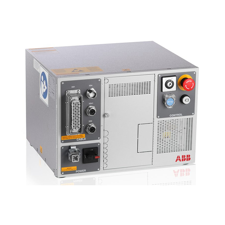
ABB RMC-100 User guide

—
ABB MEASUREMENT & ANALYTICS | 2105551MNAD
Remote Modular Controller
(RMC-100)
Startup Guide
A scalable controller supporting control and measurement
applications from simple to large oil and gas production and
transmission sites
Measurement made easy

2| RMC-100 | 2105551MNAD
—
Contents
Contents ................................................................................................................................... 2
List of figures ........................................................................................................................... 3
List of tables............................................................................................................................. 4
Additional information.............................................................................................................. 5
Compliance............................................................................................................................... 6
Cyber security .........................................................................................................................6
Waste Electrical and Electronic Equipment (WEEE) .......................................................................6
Safety ....................................................................................................................................... 7
Safety symbol conventions........................................................................................................7
Potential safety hazards............................................................................................................8
1Introduction......................................................................................................................... 9
1.1 Assumptions...................................................................................................................9
2Site planning and requirements ........................................................................................... 9
2.1 Enclosure requirements....................................................................................................9
2.2 Battery and charger requirements .....................................................................................9
2.3 External power supply requirements ..................................................................................9
2.4 Location specifications and design ................................................................................... 10
2.5 Wiring requirements ...................................................................................................... 10
3Unpack and inspect ............................................................................................................ 10
4Basic hardware installation................................................................................................ 10
4.1 Ground the controller..................................................................................................... 11
4.2 Mount the RMC ............................................................................................................. 11
4.3 Wire COMM ports .......................................................................................................... 11
4.4 Wire I/O ports............................................................................................................... 12
4.4.1 Analog input pinouts......................................................................................... 13
4.4.2 Analog output pinouts....................................................................................... 13
4.4.3 Pulse input pinouts........................................................................................... 14
4.4.4 Digital input and output pinouts ......................................................................... 14
4.5 Connect TFIO modules................................................................................................... 15
5Power the RMC................................................................................................................... 17
5.1 Power on sequence........................................................................................................ 17
5.1.1 Super capacitor................................................................................................ 18
5.2 Power with battery and charger ...................................................................................... 18
5.2.1 Connect the battery (dc power) ......................................................................... 18
5.2.2 Connect the charger ......................................................................................... 18
5.3 Power with external power ............................................................................................. 19
5.4 Lithium battery ............................................................................................................. 20
6Establish local communication ........................................................................................... 20
6.1 Local connection on USB ................................................................................................ 20
6.2 Local connection on Ethernet .......................................................................................... 21

2105551MNAD | RMC-100 | 3
6.3 Configure the station ..................................................................................................... 23
6.4 Configure security ......................................................................................................... 24
6.5 Change the LCD display ................................................................................................. 25
7Configure communications................................................................................................. 25
7.1 Configure the COMM ports.............................................................................................. 25
7.2 Configure Ethernet (network) communication ................................................................... 27
7.2.1 Configure the RMC for 1 Network mode (2-port switch) ........................................ 28
7.2.2 Configure the RMC for 2 Network mode .............................................................. 29
7.3 Expand serial communications ........................................................................................ 30
7.3.1 Expand with ABB’s XIO ..................................................................................... 30
7.3.2 Expand with third-party serial-to-Ethernet module ............................................... 30
8Configure input and output ................................................................................................ 31
8.1 Change view option ....................................................................................................... 31
8.2 Analog input configuration.............................................................................................. 31
8.3 Analog output configuration............................................................................................ 31
8.4 Digital input/digital output configuration .......................................................................... 32
8.5 Pulse input configuration ................................................................................................ 32
8.6 Expand I/O capacity with the ABB XIO ............................................................................. 33
9Configure directly attached TFIO interfaces ....................................................................... 33
10 Enable for MQTT support.................................................................................................... 36
11 Troubleshooting ................................................................................................................. 38
11.1 Visual alarm and status codes......................................................................................... 38
List of figures
Figure 4-1: Mounting the RMC ..................................................................................................... 11
Figure 4-2: COMM terminals and modules ..................................................................................... 12
Figure 4-3: Analog input pinouts .................................................................................................. 13
Figure 4-4: Analog output pinouts ................................................................................................ 14
Figure 4-5: Pulse input pinouts .................................................................................................... 14
Figure 4-6: Digital I/O pinouts ..................................................................................................... 14
Figure 4-7: TFIO module ............................................................................................................. 16
Figure 5-1: Battery port .............................................................................................................. 18
Figure 5-2: Solar panel connection ............................................................................................... 19
Figure 5-3: External power supply connection ................................................................................ 20
Figure 5-4: Lithium battery switch ................................................................................................ 20
Figure 6-1: System setup ............................................................................................................ 21
Figure 6-2: Synchronize date and time.......................................................................................... 21
Figure 6-3: Factory default Ethernet configuration .......................................................................... 22
Figure 6-4: Connection setup when using Ethernet for local communication....................................... 23
Figure 6-5: Station Setup screen.................................................................................................. 24
Figure 6-6: Security switch .......................................................................................................... 24
Figure 6-7: LCD display date and time format ................................................................................ 25
Figure 7-1: COMM port configuration ............................................................................................ 25
Figure 7-2: Add communication ................................................................................................... 26
Figure 7-3: Serial port configuration to connect XMVs ..................................................................... 27
Figure 7-4: Serial port configuration for remote communication ....................................................... 27
Figure 7-5: Network communication for 1 Network mode ................................................................ 28
4| RMC-100 | 2105551MNAD
Figure 7-6: Warning before Ethernet interface restart ..................................................................... 29
Figure 7-7: Network communication for 2 Network mode ................................................................ 30
Figure 8-1: Expert view selection ................................................................................................. 31
Figure 8-2: Analog input configuration .......................................................................................... 31
Figure 8-3: Analog output configuration ........................................................................................ 32
Figure 8-4: Digital input and output configuration........................................................................... 32
Figure 8-5: Pulse input configuration ............................................................................................ 33
Figure 9-1: TFIO-A Modules Setup................................................................................................ 34
Figure 9-2: TFIO-A Module List..................................................................................................... 34
Figure 9-3: TFIO-B Bus Enable tab (bus disabled by default) ........................................................... 35
Figure 9-4: TFIO-B Module Setup ................................................................................................. 35
Figure 9-5: TFIO-B Module List .................................................................................................... 36
Figure 10-1: RMC-100 Services .................................................................................................... 37
Figure 10-2: Enable MQTT Service and REST Service on the RMC-100............................................... 37
Figure 11-1: LCD display ............................................................................................................. 38
List of tables
Table 0-1: Related documentation ..................................................................................................5
Table 4-1: Serial communication specifications............................................................................... 11
Table 4-2: COMM 1 and COMM 2 serial communication pinouts ........................................................ 11
Table 4-3: Analog input pinouts.................................................................................................... 13
Table 4-4: Analog output pinouts.................................................................................................. 14
Table 4-5: Pulse input pinouts ...................................................................................................... 14
Table 4-6: Digital I/O pinouts....................................................................................................... 14
Table 4-7: TFIO modules ............................................................................................................. 15
Table 4-8: TFIO valve control interface module............................................................................... 16
Table 4-9: TFIO analog output (4-20 mA) module........................................................................... 16
Table 4-10: TFIO analog input module .......................................................................................... 16
Table 4-11: TFIO combo digital module and extended ..................................................................... 17
Table 4-12: TFIO thermocouple module......................................................................................... 17
Table 4-13: TFIO RTD module ...................................................................................................... 17
Table 6-1: Required Station setup................................................................................................. 23
Table 11-1: Alarms and status codes............................................................................................. 38

2105551MNAD | RMC-100 | 5
—
Additional information
Carefully read the contents of this startup guide prior to beginning installation. For any questions that are
not answered in this guide, or in the documentation listed below, call the ABB main office number on the
last page.
Additional free publications are available for download at www.abb.com/upstream or by scanning this
code:
RMC-100 product page
Table 0-1: Related documentation
Documents
Document number
RMC
-100 data sheet
2101126
RMC
-100 quick start guide
2107023
RMC
-100 safety and compliance
2107022
RMC
-100 user manual
2105552
TFIO module user manual
2101226
XIO user manual
2106424
Network communication guide
2107013
IO Interface application guide
2107011
Digital Oilfield
user manual
2106300
How to guide
– Configure MQTT
2106521
RMC
-100 AI to ABB 2600 T pressure transmitter
2105593
RMC
-100 COMM (RS-485) to ABB XMV (267/269CS/266J) W/RTD
2105579
RMC
-100 to ABB FCB Coriolis meter
2105592

6| RMC-100 | 2105551MNAD
—
Compliance
Cyber security
This product is designed to be connected, and communicate information and data, via a network
interface. All ABB Totalflow products should be connected to a secure network. It is the customer's sole
responsibility to provide,and continuously ensure,a secure connection between the product(s) and the
customer network as well as a secured and controlled physical access to the hardware equipment, or any
other network (as the case may be). The customer shall establish and maintain appropriate measures
(such as, but not limited to, the installation of firewalls, the application of authentication measures,
encryption of data, installation of antivirus programs, etc.) to protect the products, the network, its
system and its interfaces against any kind of security breaches, unauthorized access, interference,
intrusion, leakage and/or theft of data or information. ABB Inc. and its affiliates are not liable for
damages and/or losses related to security breaches, unauthorized access, interference, intrusion,
leakage and/or theft of data or information.
Although ABB provides functionality testing on the products and updates it releases, the customer should
institute its own testing program for any product updates or other major system updates (to include, but
not limited to, code changes, configuration file changes, third party software updates or patches,
hardware change-out, etc.) to ensure that the security measures the customer has implemented have
not been compromised and that the system functions in the customer's environment as expected.
Waste Electrical and Electronic Equipment (WEEE)
EU Directive 2012/19/EU
ABB Industrial Automation, Measurement and Analytics is committed to actively protecting the
environment. Do not dispose of WEEE as unsorted municipal waste. Collect WEEE separately.
Participation in the management of WEEE is critical to the success of WEEE collection.
Electrical and electronic equipment marked using the crossed-out wheeled bin symbol shall
not be mixed with general household waste. Correct disposal at a recycling facility will help
save valuable resources and prevent potential negative effects on health and the
environment. These steps ensure compliance with the Waste Electrical and Electronic
Equipment (WEEE) Directive.
Waste electrical and electronic equipment (WEEE) shall be treated separately using the national
collection framework available to customers for the return, recycling, and treatment of WEEE.

2105551MNAD | RMC-100 | 7
—
Safety
Read these instructions carefully before installation and commissioning. These instructions do not contain
all details on all types of product and do not explain all assembly, operating, or maintenance scenarios.
Ask the manufacturer for further information.
The content of these instructions is neither part of nor provided for changing a previous or existing
agreement, promise, or legal relationship. All obligations of ABB result from the respective sales contract,
which also contains the full and solely valid warranty clauses. These are neither limited nor extended by
the content of these instructions.
Observe warning signs on packaging and on the device.
Assign only qualified and authorized specialists for the assembly, electrical connection, commissioning,
and maintenance of the equipment. Specialist qualifications include:
Training or instruction and/or authorization to operate and maintain devices or systems according
to safety engineering standards for electrical circuits, high pressures, and aggressive media
Training or instruction in accordance with safety engineering standards regarding maintenance
and use of adequate safety systems
WARNING:
According to EN 60 900, use only sufficiently insulated tools for the electrical
connection
.
Also consider the following regulations:
The applicable standards and safety regulations concerning the construction and operation of
electrical installations
The regulation on technical working materials (safety guidelines for tools)
The regulations and recommendations relating to explosion protection
The recommendations for safe working in the case of installation in a Safety Integrity Level (SIL)
loop.
The regulations that apply in the country of use
The device can be operated at high levels of pressure and with aggressive media. Serious injury and/or
considerable material damage can result if this device is handled incorrectly.
Safety symbol conventions
The following conventions appear throughout this document:
DANGER and WARNING hazards relate to personal injury and NOTICE hazards are associated with
equipment or property damage. However, under certain operating conditions, operating damaged
equipment can result in a degraded system or process performance leading to serious or life-threatening
injuries. Therefore, compliance with all DANGER, WARNING and NOTICE hazards is required at all times.
DANGER
–Serious damage to health / risk to life. These symbols, and the signal word
"DANGER", indicate imminent danger or electrical hazard. Failure to observe this safety
information will result in death or severe injury. The text may state the hazard, how to avoid
the hazard, and the result if not followed. The
lightning bolt is for electrical danger; the
exclamation point is for general dangers.
WARNING
– Bodily injury. These symbols, and the signal word "WARNING", indicate a
potentially dangerous situation. Failure to observe this safety information
could result in death
or severe injury. The text may state the hazard, how to avoid the hazard, and the result if not
followed. The bolt is fo
r electrical warnings; the exclamation point is for general warnings.
!
!

8| RMC-100 | 2105551MNAD
NOTICE
– Equipment damage, cybersecurity risk, or loss of data. This symbol
indicates a potential for equipment damage, loss
of data or another unintended outcome.
Failure to observe this information may result in damage to or destruction of the product
and / or other system components.
IMPORTANT NOTE:
This symbol indicates operator tips, particularly useful information, or
important information about the product or its further uses
.
Potential safety hazards
The Remote Modular Controller operates on 9 to 30 Vdc. There are no hazardous voltages present in the
controller. There are no chemical or burn hazards. However, some optional power sources might convert
power from Vac to Vdc.
Pressurized natural gas is present in the measurement pipeline. Natural gas can escape from the pipeline
during installation, calibration, or following damage to the pipeline. Only properly trained and authorized
personnel should work in hazardous locations.
WARNING
– Bodily injury. Read and follow instructions contained in this guide before and
during equipment installation. Failure to do so could result in bodily
injury or equipment
damage.
WARNING
– Bodily injury. Apply power only after the procedures are complete. Technicians
must perform the procedures in order: plan, install, wire, verify the power
-on sequence, and
configure.
WARNING
– Bodily injury. The device can be operated at high levels of pressure and with
aggressive media. Serious injury and/or considerable material damage can be caused if this
device is handled incorrectly.
WARNING
– Bodily injury. Ensure there is no hazardous atmosphere present when performing
maintenance on the unit. Do not separate components when energized. This applies to all
connectors and connections, cabling and wiring.
WARNING – Bodily injury. The RMC-100 startup guide does not address any requirements
for
the installation of product(s) in hazardous (classified) locations. Refer to the installation
instructions and local and national electrical codes for installation requirements in hazardous
(classified) locations.
WARNING
– Bodily injury.
Field wiring cables and wires can be energized from optional power
sources other than the RMC. Disconnecting energized cabling or wiring would cause a spark that
would ignite a hazardous atmosphere if present.
NOTICE
– Equipment damage. Potenti
al electrostatic charging hazard: clean only with damp
cloth
.
!
!

2105551MNAD | RMC-100 | 9
—
1Introduction
The startup guide is designed for typical installations only. Installations must be performed by personnel
knowledgeable of the Remote Modular Controller 100, local and national codes, communication wiring,
and electrical wiring. Many sites have unique system installation requirements. In these cases, it is
important to reference site-specific documentation.
In this startup guide, the Remote Modular Controller 100 will be referred to as the RMC or the controller,
unless otherwise indicated.
1.1 Assumptions
The software PCCU32 version 7.68 or newer is installed and operational on the PC used to
communicate with the RMC equipment for configurations. PCCU32 version 7.68 fully supports the
2-port switch mode for Ethernet and connections with the XIO.
Installation and maintenance will only be conducted by personnel authorized to work on electrical
installations.
Installation and maintenance will be conducted in accordance with relevant national and local
codes.
2Site planning and requirements
Installing the RMC requires that customer-supplied enclosures, power sources, wiring, and location
comply with the specifications described in this section.
WARNING
– Bodily injury. Carefully review the specifications listed in this section to select
compliant equipment. Failure to comply with these speci
fications may create unsafe conditions,
resulting in bodily injury and equipment damage.
2.1 Enclosure requirements
The RMC must be installed in an enclosure complying with the following specifications:
Enclosure must protect the RMC-100 against shock and impact.
For Class I, Division 2, or other outdoor installations, the RMC-100 shall be installed in an
enclosure rated at least Type 3R, according to the environment.
For Class I, Zone 2 installations, the RMC-100 shall be installed inside an enclosure tested for
IP54 in accordance with IEC 60529 and IEC 60079-15.
2.2 Battery and charger requirements
When powering the controller with a battery (battery mode), comply with the following specifications:
Battery specifications:
•Nominal 12 Vdc Sealed Lead Acid
•RMC rating for ambient temperature with battery is Ta = -40 °C to +60 °C (-40 °F to 140 °F)
Battery charger specifications:
•Solar panel must be nominal 12 Vdc, 20W or less, or
•Power source: 14.5 Vdc to 15.5 Vdc, 1.65 A
2.3 External power supply requirements
When powering the controller with external power (EXT PWR mode), comply with the following
specifications:
Power supply must provide power not exceeding the voltage range allowed by the RMC. EXT PWR
mode operation is +9 Vdc to 30 Vdc, 5A maximum.
RMC rating for ambient temperature without battery is Ta = -40 °C to +70 °C (-40 °F to 158 °F).
NOTICE
– Equipment damage. A battery cannot be used when the controller is in the EXT PWR
mode.
!

10 | RMC-100 | 2105551MNAD
2.4 Location specifications and design
Decide on the location to install the controller. The RMC mounts on a DIN rail. Mount the DIN rail in an
enclosure or on an interior wall that meets the environmental ratings for the location (see details in
section 2.1, Enclosure requirements).
The RMC mounting surface must have sufficient strength to support the hanging weight of the controller
(maximum of 1.816 pounds) and associated equipment to meet the requirements of IEC715. The
installation location should allow access to the RMC, power sources, cables, and connections.
If a solar panel is used, decide where and how to install the solar panel outdoors. For optimum charging,
avoid placing the solar panel where it will be in shadows any part of the day.
2.5 Wiring requirements
All wiring connections and screw terminals for power, input ports, output ports, and communications
support 12 AWG to 22 AWG. Wire gauge selection should be based on the voltage and current
requirements of the circuitry as well as the expected length of the wires. The gauge differs for each
application.
Follow local electrical codes when selecting the appropriate wire gauge and type based on the load
current, voltage, signal type, wire length, and indoor or outdoor application.
NOTICE
– Equipment damage. Field installation cable and conductors must be rated
greater than 70 °C w
hen installed in an ambient temperature greater than 60 °C.
3Unpack and inspect
IMPORTANT NOTE:
If there is any damage to the shipping carton, keep it and the packing
materials until the contents are inspected and found to be free of damage
.
To unpack the RMC and inspect for damaged, missing or incorrect parts:
1. Inspect the shipping carton for damage.
2. Carefully remove items from the carton.
3. Keep all shipping materials to return any parts.
4. Compare the packing list with the materials received. Check for missing or incorrect parts.
5. Inspect the items for damage:
RMC exterior
LCD display
Optional equipment if purchased
6. If there are any missing, incorrect, or damaged parts or noticeable defects, call the ABB main
office number listed on the last page of this guide.
4Basic hardware installation
This is an overview of basic hardware installation. For different installations, refer to the RMC user
manual or call the ABB main office number listed on the last page of this guide.
NOTICE
– Equipment damage. Perform all procedures in the order presented in this section
before powering the RMC
.
DANGER
– Serious damage to health / risk to life. Allowing the RMC components to
make contact with a non
-insulated tool or without a proper grounding device could create a
static electric discharge resulting in bodily injury and damage to the electronic components.
Use properly insulated tools and wear a grounding strap to eliminate static electricity when
connecting or disconnecting wires.

2105551MNAD | RMC-100 | 11
4.1 Ground the controller
The RMC must be grounded by mounting on a grounded DIN rail.
NOTICE
– Equipment damage. The DIN rail on which the controller is mounted must be
bonded to an earthing terminal. The bonding conductor must have a cross sectional area of at
least 12 AWG or 4 mm
2.
To ground the DIN rail:
1. Screw the DIN rail onto the mounting surface.
2. Attach a grounding wire to the DIN rail.
3. Attach the other end of the grounding wire to an electrical ground.
4.2 Mount the RMC
To mount the controller on the DIN rail:
1. Position the RMC on the DIN rail.
2. Push the RMC onto the DIN rail until it snaps into place (Figure 4-1).
Figure 4-1: Mounting the RMC
IMPORTANT NOTE:
To remove the controller, use a slotted screwdriver inserted in the
access slot of the DIN rail release clip to loosen the clip. For more information, refer to the
Maintenance and Service
section in the RMC User Manual.
4.3 Wire COMM ports
Wire the RMC COMM ports to communicate with and power external devices. Wiring for communication
depends on the type of serial interface required by the device. Wiring for power is required if there is no
external supply powering the device.
Table 4-1 provides the specifications for the serial communication ports.
Table 4-1: Serial communication specifications
Type
Maximum Length
Termination
RS-232
50 feet (15 meters)
Terminal connector (9 POS), screw termination and
pluggable COMM module
Active when communication module is inserted
RS-485 or RS-422
4000 feet (1220 meters)
Table 4-2 identifies RS-232, RS-422, and RS-485 communication pinouts for COMM 1 and COMM 2.
Table 4-2: COMM 1 and COMM 2 serial communication pinouts
PIN
RS-232
RS-422
RS-485
1
Voltage Out (VOUT)
Voltage Out (VOUT)
Voltage Out (VOUT)
2
Ground (GND)
Ground (GND)
Ground (GND)
3
Switched voltage
(Sw VOUT)
Switched voltage
(Sw VOUT)
Switched voltage
(Sw VOUT)

12 | RMC-100 | 2105551MNAD
PIN
RS-232
RS-422
RS-485
4
Operate (OPER)
Operate (OPER)
Operate (OPER)
5
Remote request to send (RRTS)
6
Request to send (RTS)
Transmit bus+ (TBUS+)
Transmit/Receive (BUS+)
7
Transmit data (TX)
Transmit bus- (TBUS-)
Transmit/Receive (BUS-)
8
Receive data (RX)
Receive bus+ (RBUS+)
Not Used
9
Clear to send (CTS)
Receive bus- (RBUS-)
Not Used
Refer to the RMC user drawings for COMM wiring details for specific external devices. See the Additional
information section.
To wire the serial communication port:
NOTICE
– Equipment damage. An external device can be powered from pin 1 (VOUT) or pin 3
(Sw VOUT) on both COMM1 and COMM2. The output voltage at these pins is dependent upon the
external power supply connected to the CHARGER/EXT PWR port.
Bef
ore connecting to these pins, ensure that the device is compatible with the input voltage at the
CHARGER/EXT PWR port. Connecting an incompatible device may result in damage to the device.
1. Use a slotted screwdriver to pry the terminal connector off the electronic board.
2. Trim the wire covering back ¼ inch on each wire.
3. Loosen the terminal connector screws for the correct pin according to Table 4-2.
4. Insert the wires in the required pins. If powering the device from the COMM port:
a. Use pin 1 (VOUT) and pin 2 (GND) to provide constant voltage.
b. Use pin 3 (Sw VOUT) and pin 2 (GND) to provide switched voltage.
5. Tighten the terminal connector screws.
NOTICE
– Equipment damage. Do not overtighten the terminal connector screws as this may
damage the wire.
6. Insert the terminal connector back onto the COMM port if it was removed.
7. Insert the communication module in the appropriate slot (Figure 4-2). The communication module
pushes the port cover downward when inserted.
Figure 4-2: COMM terminals and modules
4.4 Wire I/O ports
Wire the RMC I/O ports to monitor, control and power external devices. Wiring for power is required if
there is no external supply powering the device. Refer to the RMC user drawings for I/O wiring details for
specific external devices. See the Additional information section.
To wire the I/O port:
NOTICE
– Equipment damage.
An external device can be powered from pin 1 (PWR) on any of
the AIs (
Table 4-3) or the AO (Table 4-4). The output voltage at the PWR pin is dependent upon
the external power suppl
y connected to the CHARGER/EXT PWR port.

2105551MNAD | RMC-100 | 13
Before connecting to these pins, ensure that the external device is compatible with the input
voltage at the CHARGER/EXT PWR port. Connecting an incompatible device may result in damage
to the device.
1. Use a slotted screwdriver to pry the terminal connector off the electronic board.
2. Trim the wire covering back ¼ inch on each wire.
3. Loosen the terminal connector screws for the correct pin according to the I/O tables. See sections
4.4.1, 4.4.2, 4.4.3 and 4.4.4 in this guide.
4. Insert the wires in the required pins. If powering the device from the AI or the AO:
a. Use pin 1 (PWR) and pin 3 (GND) for devices attached to the AI.
b. Use pin 1 (PWR) and pin 4 (GND) for devices attached to the AO.
5. Tighten the terminal connector screws.
NOTICE
– Equipment damage. Do not overtighten the terminal connector screws as this
may damage the wire
.
6. Insert the terminal connector back on the I/O port if it was removed.
4.4.1 Analog input pinouts
Table 4-3 and Figure 4-3 identify the AI pinouts.
NOTICE
– Equipment damage. Before connecting to pin 1 (PWR), ensure that the external
device is compatible with the input voltage at the CHARGER/EXT PWR port. Connecting an
incompatible device may result in damage to the device.
Table 4-3: Analog input pinouts
Input
Pin
Description
Input
Pin
Description
1
1
PWR - Power
3
1
PWR - Power
2
AI - Input signal
2
AI - Input signal
3
GND - Input ground
3
GND - Input ground
2
1
PWR - Power
4
1
PWR - Power
2
AI - Input signal
2
AI - Input signal
3
GND - Input ground
3
GND - Input ground
Figure 4-3: Analog input pinouts
4.4.2 Analog output pinouts
Table 4-4 and Figure 4-4 identify the AO pinouts.
NOTICE
– Equipment damage. Before connecting to pin 1 (PWR), make sure that the
external device is compatible with the input voltage at the CHARGER/EXT PWR port.
Connecting an incompatible device may result in damage to the device.

14 | RMC-100 | 2105551MNAD
Table 4-4: Analog output pinouts
Output
PIN
Description
1
1
PWR - Loop power input
2
SNK - Current sink input
3
SRC - Current source output
4
GND - Ground
Figure 4-4: Analog output pinouts
4.4.3 Pulse input pinouts
Table 4-5 and Figure 4-5 identify the PI pinouts.
Table 4-5: Pulse input pinouts
Input
PIN
Description
1
1
INP - Pulse input 1
2
GND - Ground
2
1
INP - Pulse input 2
2
GND - Ground
Figure 4-5: Pulse input pinouts
4.4.4 Digital input and output pinouts
Table 4-6 and Figure 4-6 identify the DI/DO pinouts.
Table 4-6: Digital I/O pinouts
DI/DO
PIN
Description
DI/DO
PIN
Description
1
1
SIG−Signal DI/DO 1
1
1
SIG−Signal DI/DO 4
2
GND−ground
2
GND−ground
2
1
SIG−Signal DI/DO 2
2
1
SIG−Signal DI/DO 5
2
GND−ground
2
GND−ground
3
1
SIG−Signal DI/DO 3
3
1
SIG−Signal DI/DO 6
2
GND−ground
2
GND−ground
Figure 4-6: Digital I/O pinouts

2105551MNAD | RMC-100 | 15
4.5 Connect TFIO modules
The RMC has two TFIO ports. Each TFIO port requires a TFIO installation kit which includes the cable to
connect the TFIO modules to the RMC. For additional information, refer to the TFIO Module User Manual.
See Additional
NOTICE
– Equipment damage. When the TFIO interface is disabled, the module(s) remain
powered. Remove the power from the RMC before connecting or disconnecting additional TFIO
module(s) or
the TFIO cable. Failure to power down the RMC may result in damage to the
module(s).
Table 4-7 identifies the different module types available. The RMC does not support the TFIO CIM module
part number 2100421 supported by other Totalflow equipment. For serial port capacity expansion
options, see section 7.3 Expand serial communications.
IMPORTANT NOTE:
Ta b l e 4 -7 includes module and embedded software base part numbers
only
. The same part number is used for each module type. An additional revision-level
number identifies the module generation.
For example, for the Valve Control Combo I/O
module, a module with part number
2100412-001 identifies a legacy (green) module, while
part number 2140412
-010 identifies a newer module.
Table 4-7: TFIO modules
TFIO module
Part number
TFIO software version
Valve Control Combo I/O
2100412
2100576
4–20 mA Analog Output
2100415
2100715
Type II Analog Input
2100418
2100575
Combo Digital
2100543
2100563
Thermocouple
2100869
2101024
RTD
2101018
2101027
NOTICE
– Equipment damage.
Power compatibility for TFIO modules depends on module
generation
:
Older green modules must only use 12 Vdc.
M2 modules and newer gray modules can use 12 or 24 Vdc.
A combination of green modules and M2 modules or gra
y modules must only use 12
Vdc.
To connect the TFIO module(s):
1. Attach the TFIO module to the DIN rail.
2. Attach the TFIO interface cable to the first TFIO module.
3. Attach the next TFIO module to the DIN rail.
4. Position it beside the previously attached module and snap them together.
5. Repeat steps 3 and 4 to attach the additional TFIO modules as required.
IMPORTANT NOTE:
A maximum of 22 modules is supported by each port. The T
FIO A port
does not have to be full before using TFIO B.
6. Attach the 9-pin connector of the TFIO interface cable to the TFIO A port on the RMC.
7. Using the second TFIO interface cable, repeat steps 1 through 5 for the TFIO B port.
8. Attach the 9-pin connector of the TFIO interface cable to the TFIO B port.
9. Loosen the terminal connector screws for the correct pin according to Table 4-8.
10. Insert the wires in the required TFIO pins.
11. Tighten the terminal connector screws.

16 | RMC-100 | 2105551MNAD
NOTICE
– Equipment damage. Do not overtighten the terminal connector screws as this may
damage the wire
.
Figure 4-7 shows the side view of a TFIO module and its pinouts.
Table 4-8 through Table 4-13 identify the wiring pins for the TFIO modules used with the RMC. The
wiring pins are the same for legacy TFIO modules.
NOTICE
– Equipment damage. The output voltage at the following pins is dependent upon the
external power supply connected to the CHARGER/EXT PWR port:
J2
-1, J4-1 and J4-3 (Table 4-8) and J1-1, J2-1, J3-1, J4-1 (Table 4-9)
Before connecting to these pins, make sure that the external device is compatible with the input
voltage at the CHARGER/EXT PWR port
.
Table 4-8: TFIO valve control interface module
J1
J2
J3
J4
1
POINT 1 SIG
AO Vdc source
POINT 3 SIG
POINT 5 SIG
2
POINT 1 GND
AO Isink
POINT 3 GND
POINT 6 SIG
3
POINT 2 SIG
AO Isource
POINT 4 SIG
POINT 7 SIG
4
POINT 2 GND
AO Vdc common
POINT 4 GND
POINT 8 SIG
Table 4-9: TFIO analog output (4-20 mA) module
J1
J2
J3
J4
1
AO1 Vdc source
AO2 Vdc source
AO3 Vdc source
AO4 Vdc source
2
AO1 Isink
AO2 Isink
AO3 Isink
AO4 Isink
3
AO1 Isource
AO2 Isource
AO3 Isource
AO4 Isource
4
AO1 Vdc common
AO2 Vdc common
AO3 Vdc common
AO4 Vdc common
Table 4-10: TFIO analog input module
J1
J2
J3
J4
1
AI1 (+)
AI3 (+)
AI5 (+)
AI7 (+)
2
AI1 (GND)
AI3 (GND)
AI5 (GND)
AI7 (GND)
3
AI2 (+)
AI4 (+)
AI6 (+)
AI8 (+)
4
AI2 (GND)
AI4 (GND)
AI6 (GND)
AI8 (GND)
Figure
4-7: TFIO module
Side View Pins
M2

2105551MNAD | RMC-100 | 17
Table 4-11: TFIO combo digital module and extended
J1
J2
J3
J4
1
POINT 1 SIG
POINT 3 SIG
POINT 5 SIG
POINT 7 SIG
2
POINT 1 GND
POINT 3 GND
POINT 5 GND
POINT 7 GND
3
POINT 2 SIG
POINT 4 SIG
POINT 6 SIG
POINT 8 SIG
4
POINT 2 GND
POINT 4 GND
POINT 6 GND
POINT 8 GND
Table 4-12: TFIO thermocouple module
J1
J2
J3
J4
1
Shield
Shield
Shield
Shield
2
TC1 (J-Wht/K-Yel)
TC2 (J-Wht/K-Yel)
TC3 (J-Wht/K-Yel)
TC4 (J-Wht/K-Yel)
3
TC1 Red (-)
TC2 Red (-)
TC3 Red (-)
TC4 Red (-)
4
Shield
Shield
Shield
Shield
Table 4-13: TFIO RTD module
J1
J2
J3
J4
1
OUT
OUT
OUT
OUT
2
(+)
(+)
(+)
(+)
3
(-)
(-)
(-)
(-)
4
IN
IN
IN
IN
See section 8.6 to configure the TFIO interfaces.
5Power the RMC
This section describes two modes for powering the controller:
Battery mode: Power is supplied by a 12 volt battery with a charger (see section 5.2.)
External power mode: Power is supplied by an external power source (see section 5.3.)
Review section 5.1, follow the instructions for the appropriate power mode, then continue to section 5.4
Lithium battery.
NOTICE
– Equipment damage.
Power compatibility for TFIO modules depends on module
generation
:
Older green modules must only use 12 Vdc.
M2 modules and newer gray modules can use 12 or 24 Vdc.
A combination of green modules and M2 modules or gra
y modules must only use 12
Vdc.
5.1 Power on sequence
The RMC power on sequence is initiated as soon as power is connected. The following information may be
displayed on the LCD as the controller completes its startup:
ABB TOTALFLOW RMC-100: identifies the controller name and model
BOOT 2105412-XXX: indicates the version of the boot software
OS 2105411-XXX: indicates the version of the operating system
Super CAP Charged: indicates if the super capacitor is charged (see section 5.1.1.)
APP 2105457-XXX: indicates the flash version
IMPORTANT NOTE:
The scrolling duration of the displayed items may vary. When the
DATE/TIME displays, the power on sequence is completed.

18 | RMC-100 | 2105551MNAD
5.1.1 Super capacitor
The RMC design includes a super capacitor (Super CAP) that serves as a short-term power reservoir. The
first time that the unit is powered up, or if the RMC is left powered off for several hours or longer, the
boot time is approximately 2 minutes to allow for charging of the super capacitor. Once the capacitor is
fully charged, the boot time is considerably less.
IMPORTANT NOTE:
In the event of a loss of power or reset, the charged super capacitor
prevents the supply voltage from falling to zero for a short period of time (2.5 seconds).
This delay allows the system time to save all persistent data such as
trending, restart
configuration, etc.
5.2 Power with battery and charger
This powering mode requires a 12 volt (SLA) battery and a charger to recharge the battery. The following
instructions describe the typical installation of a battery and solar panel system as the charger. These
instructions should be adapted for alternate installations.
IMPORTANT NOTE:
Make sure the battery and charger meet the specifications
requirements
given in section 2.2.
5.2.1 Connect the battery (dc power)
The hardware required for a battery installation is a 12 volt sealed lead acid (SLA) battery and the
battery cable. Before installation, inspect the battery cable and connectors for breakage where they
terminate on the battery. To install and connect the battery:
1. Install and secure the battery where it will be used.
WARNING
– Bodily injury and property damage.Do not allow the battery terminals or
cable ends
, if attached, to come in contact with any metal surface. When the positive and
negative battery terminals contact a conductive material, this creates a short circuit and
could result in sparks, property damage, and possible explosion.
2. Connect the battery to the terminals (Figure 5-1). The power terminal block is green. Observe the
polarity (+ and -).
WARNING
– Bodily injury and property damage.All wiring of peripheral or external
devices to the controller should be com
pleted prior to applying power (connecting the
battery).
Connect the battery before connecting the charger cable.
Figure 5-1: Battery port
3. Confirm that the battery is supplying power to the RMC by observing the power on sequence
information scrolling on the LCD (see details in section 5.1). When the DATE/TIME display, the
sequence is complete.
4. If the power on sequence fails to initiate or complete, press the reset button shown in Figure 5-4.
5.2.2 Connect the charger
The RMC may use a solar panel (20 Watt or less) with Nominal 12 Vdc output voltage. The solar panel
may be mounted on a 2 inch pipe or the top or side of a meter house. Call the ABB main office number
BAT CHARGER/EXT PWR
Battery port

2105551MNAD | RMC-100 | 19
listed on the last page of this guide for questions about mounting the solar panel on the top or side of a
meter house.
NOTICE
– Equipment damage.
Alternate installations could use a power source instead of a solar
panel charger. When using a
power source, the output must be 14.5 Vdc to 15.5 Vdc maximum as
described in section
2.2.
Failure to use chargers that meet the required voltage specifications may cause equipment
damage.
Exercise caution when handling the solar panel to avoid damaging it.
For optimum charging, avoid placing the solar panel where it will be in shadows for any part of the day.
The hardware required to connect the solar panel to the RMC is:
One solar panel with an integrated cable
One solar panel mounting kit
NOTICE
– Equipment damage. Never connect the solar panel or alternate charger cable to the
RMC before the battery is connected to the BAT port (
Figure 5-1).
To connect the solar panel charger (adapt instructions if connecting to a power source as a charger):
1. Verify that the solar panel is operating properly before installation:
a. Check the solar panel using a digital voltmeter to verify polarity and output voltage. Voltage
varies depending on the amount of sun, angle to sun, etc.
b. If the measured output voltage is within the manufacturer’s specification as defined by the
specification sheet supplied with the panel, continue with the installation.
c. If the measured voltage is out of specification, call the ABB main office number listed on the
last page of this guide for a replacement panel.
2. Connect the solar panel cable to the CHARGER/EXT PWR terminals as shown in Figure 5-2.
Observe the polarity (+ and -).
Figure 5-2: Solar panel connection
3. Mount the solar panel facing up from the horizon at a 50°angle. For northern hemispheres,
position the solar panel facing south. For southern hemispheres, position the solar panel facing
north.
Clean the solar panel on a regular basis to ensure maximum charging.
Continue to section 5.4 Lithium battery.
5.3 Power with external power
The controller can be powered from an external power supply (9 to 30 Vdc).
IMPORTANT NOTE:
Make sure that the external power supply meets the specifications
given
in section 2.3.
BAT CHARGER/EXT PWR
Solar
panel

20 | RMC-100 | 2105551MNAD
NOTICE
– Equipment damage. A battery cannot be used when the controller is in the EXT
PWR mode.
To wire an external power supply to the controller:
1. Follow the manufacturer’s instructions supplied with the external power supply to install and
connect it to a power source.
2. Connect the external power supply cable to the CHARGER/EXT PWR terminals as shown in Figure
5-3. Observe the polarity (+ and -).
Figure 5-3: External power supply connection
3. Apply power to the external power supply.
4. Confirm that the RMC is receiving power by observing the power on sequence information scrolling
on the LCD (see details in section 5.1). When the DATE/TIME display, the sequence is complete.
5. If the power on sequence fails to initiate or complete, press the reset button shown in Figure 5-4.
5.4 Lithium battery
The lithium battery serves to retain operation of the real time clock with the lithium battery backup
switch. The switch is located between the TFIO ports and is accessed by a slot in the housing. Lift the
cover over the TFIO ports to view the switch settings. The two settings are:
Enable: The switch is on. The lithium battery backs up the real time clock. If power is lost or
disconnected, the real time clock continues to operate until the lithium battery is depleted.
Disable: The switch is off. The lithium battery does not back up the real time clock.
To ensure the lithium battery is enabled, insert a small screwdriver in the slot and move the switch to
the ENABLE position as shown in Figure 5-4.
Figure 5-4: Lithium battery switch
6Establish local communication
Establish initial communication with the RMC-100 with a direct connection to the USB or Ethernet ports.
6.1 Local connection on USB
Local communication between a host system (laptop or PC) and the RMC can be established by a direct
USB connection.
The following instructions are for a USB port connection. The required USB cable has a USB 2.0 Type B
plug to a USB 2.0 Type A plug.
External
Power
Supply
BAT CHARGER/EXT PWR
RESET LITH
BAT
SECUR.
ENABLE
ON
OFF
TFIO cover
Lift cover to
access settings
Lithium battery
switch
Reset
Other manuals for RMC-100
3
Table of contents
Other ABB Controllers manuals

ABB
ABB PSTX370 User manual

ABB
ABB DOL Starter User manual

ABB
ABB ACS880 Series Use and care manual

ABB
ABB UMC100.3 User manual

ABB
ABB HART RSDE10 User manual

ABB
ABB Contrac PME120AI User manual

ABB
ABB ACS880-37 User manual

ABB
ABB RTC-F-1.PB User manual

ABB
ABB ACH550-UH HVAC Instruction manual

ABB
ABB Relion 611 Series User manual

ABB
ABB i-bus KNX User manual

ABB
ABB ACS 800 Series Use and care manual

ABB
ABB ACS150 series User manual

ABB
ABB ACS880 Series User manual

ABB
ABB i-bus KNX AC/S 1.x.1 Series User manual

ABB
ABB ACH550-01 User manual

ABB
ABB ACS 800 Series User manual

ABB
ABB PLUTO Safety-PLC User manual

ABB
ABB ACH400 Series User manual

ABB
ABB ACS150 series User manual