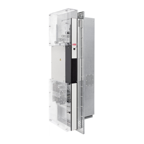
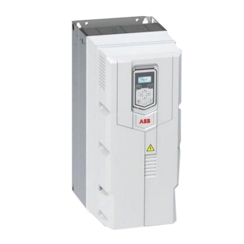
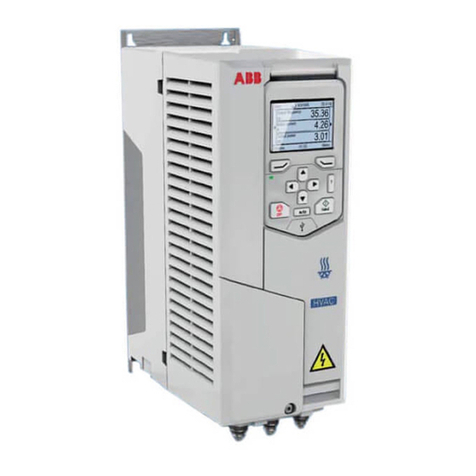
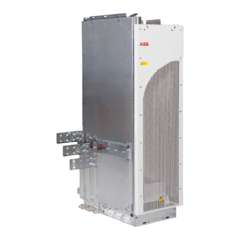
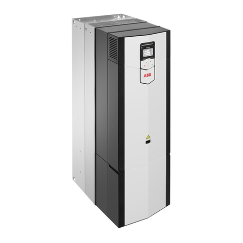
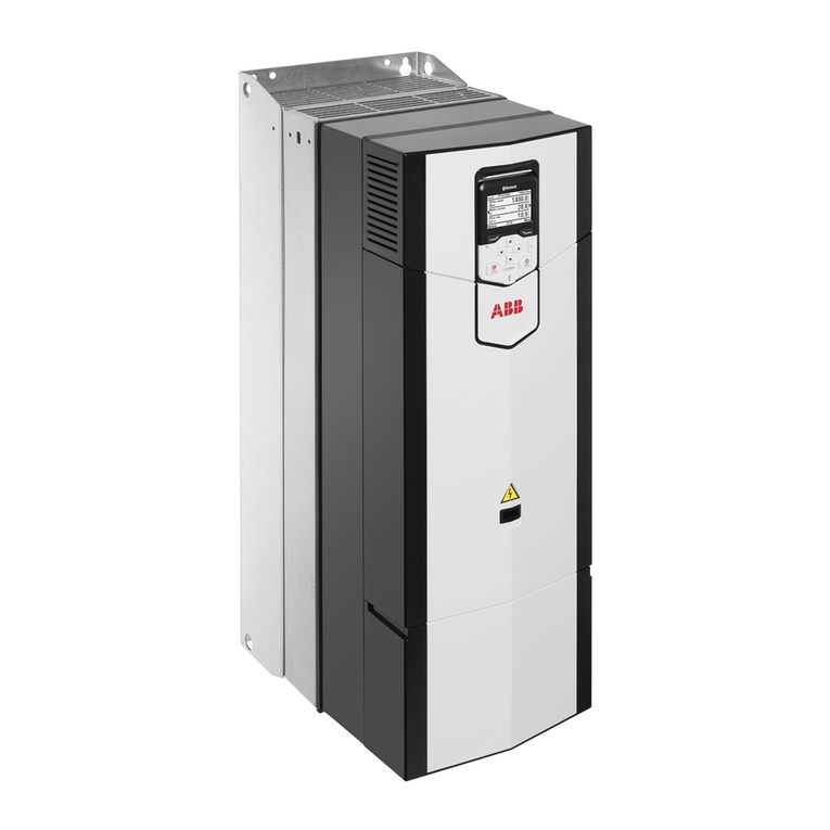
ABB DCS880 series User manual

DCS880
DCS880 Service manual

DCS880 Drive Manuals
All the documents available for the drive system DCS880 are listed below:
List of manuals
Language
Publication number
E
D
I
ES
F
CN
RU
General
DCS880 Quick Guide
3ADW000480
x
DCS880 Documentation pack
DCS880 CD
download
x
DCS880 Units
DCS880 Flyer
3ADW000475
x
x
x
DCS880 Technical Catalog
3ADW000465
x
DCS880 Hardware Manual
3ADW000462
x
DCS880 Firmware Manual
3ADW000474
x
DCS880 Service Manual
3ADW000488
x
ACS-AP-x assistant control panels user’s manual
3AUA0000085685
x
Adaptive programming, Application guide
3AXD50000028574
x
Functional safety
Safety instructions all languages
3ADW000481
x
x
x
x
x
x
x
Supplement for functional safety
3ADW000452
x
Option manuals and guides
SDCS-DPI-H01 panel bus adapter module
HW DCT880 0001E
x
Door mounting kits
DPMP-01 mounting platform for ACS-AP control panel
3AUA0000100140
x
DPMP-02 mounting platform for ACS-AP control panel
3AUA0000136205
x
Serial communication
FCAN-01 CANopen adapter module
3AFE68615500
3AUA0000121752
x
x
FDNA-01 DeviceNet™ adapter module
3AFE68573360
x
FECA-01 EtherCAT adapter module
3AUA0000068940
3AUA0000083936
x
x
FENA-01/-11/-21 Ethernet adapter module
3AUA0000093568
x
FEPL-02 Ethernet POWERLINK adapter module
3AUA0000123527
3AUA0000133138
x
x
FPBA-01 PROFIBUS DP adapter module
3AFE68573271
3AFE68989078
x
x
FSCA-01 RS-485 adapter module
3AUA0000109533
x
FDCO-01/02 DDCS communication modules
3AUA0000114058
Drive (IEC61131-3) application programming manual
3AUA0000127808
x
Tool and maintenance manuals and guides
Drive composer PC tool
3AUA0000094606
x
NETA-21 remote monitoring tool
3AUA0000096939
x
NETA-21 remote monitoring tool installation and
startup guide
3AUA0000096881
x
Extension modules
FIO-11 Analog extension module
3AFE68784930
x
FIO-01 Digital extension module
3AFE68784921
x
FAIO-01 Analog extension module
3AUA0000124968
x
FEN-01 TTL encoder interface
3AFE68784603
x
FEN-31 HTL encoder interface
3AUA0000031044
x
FEA-01 F-series extension adapter
3AUA0000071412
x
FEA-03 F series extension adapter
3AUA0000115811
x
x →existing p →planned
Status 11.2017
DCS880 Manuals list e e.docx

3
Table of contents
3ADW000488R0101 DCS880 Service manual e a
Table of contents
DCS880 Drive Manuals ........................................................................................................................................2
List of manuals..................................................................................................................................................2
Table of contents 3
Safety instructions 6
What this chapter contains ...................................................................................................................................6
To which products this chapter applies ................................................................................................................6
Usage of warnings and notes ...............................................................................................................................6
Installation and maintenance work .......................................................................................................................6
Grounding .........................................................................................................................................................7
Printed circuit boards and fiber optic cables.....................................................................................................7
Mechanical installation..........................................................................................................................................7
Operation ..............................................................................................................................................................8
Introduction to this manual 9
Chapter overview..................................................................................................................................................9
Before You Start ...................................................................................................................................................9
What this manual contains....................................................................................................................................9
Target group .........................................................................................................................................................9
Related documents...............................................................................................................................................9
Storage and transport ...........................................................................................................................................9
Name plate .........................................................................................................................................................10
Type code ...........................................................................................................................................................11
Voltage ratings....................................................................................................................................................12
Current ratings ....................................................................................................................................................13
Terms and abbreviations ....................................................................................................................................14
Cybersecurity disclaimer.....................................................................................................................................15
Fault Tracing Thyristors 16
Tools ...................................................................................................................................................................16
For commissioning and fault tracing...............................................................................................................16
Additionally for service and preventive maintenance .....................................................................................17
How to detect a faulty thyristor ...........................................................................................................................17
A fuse is blown................................................................................................................................................17
DC-current pulses measured using an oscilloscope ......................................................................................17
Thyristor test ...................................................................................................................................................18
Ripple monitor.................................................................................................................................................18
How to find a faulty thyristor ...........................................................................................................................18
Converters size H1 … H4 (20 ... 1000 A) .......................................................................................................19
Blown fuses ....................................................................................................................................................19
Converters size H5 … H8 (900 ... 5200 A) .....................................................................................................20
Blown fuses ....................................................................................................................................................20
Ripple monitor.................................................................................................................................................21
How to detect a faulty SDCS-BAB-F0x (H1 ... H4).............................................................................................22
How to find a faulty SDCS-BAB-F0x ..................................................................................................................22
Converters size H1 … H3 (20 ... 520 A) .........................................................................................................22
Converters size H4 (610 ... 1000 A) ...............................................................................................................24
Handling the Semiconductors 26
General Instruction how to handle semiconductors ...........................................................................................26
Exchange thyristors sizes H1 … H4 27
Installation of thyristor modules and SDCS-BAB-F0x in converters size H1 … H4 (20 ... 1000 A) ...................27
Required tools.................................................................................................................................................27
Find faulty thyristor modules...........................................................................................................................27

4
Table of contents
3ADW000488R0101 DCS880 Service manual e a
Remove faulty thyristor modules ....................................................................................................................28
Install new thyristor modules ..........................................................................................................................33
Remove faulty SDCS-BAB-F0x ......................................................................................................................35
Install new SDCS-BAB-F0x ............................................................................................................................36
Thyristor module and SDCS-BAB-F0x location in DCS880-S01 (2-Q) units..................................................37
Thyristor module and SDCS-BAB-F0x location in DCS880-S02 (4-Q) units..................................................39
Thyristor module terminals and SDCS-BAB-F0x............................................................................................40
Exchange thyristors size H6 41
Installation of thyristor modules in converters size H6 (900 … 2000 A).............................................................41
Required tools.................................................................................................................................................41
Find faulty thyristor modules...........................................................................................................................42
Remove faulty thyristor ...................................................................................................................................43
Install new thyristor .........................................................................................................................................44
Location of thyristors in frame H6 (4-Q bridge) ..............................................................................................45
Location of thyristors in frame H6 (2-Q bridge) ..............................................................................................45
Location of branch fuses frame H6.................................................................................................................46
Exchange thyristors size H7 47
Installation of thyristor modules in converters size H7 (1900 … 3000 A)...........................................................47
Required tools.................................................................................................................................................47
Bidirectional-Controlled-Thyristors (BCTs) .....................................................................................................48
Find faulty thyristor modules...........................................................................................................................49
Remove faulty thyristor ...................................................................................................................................50
Install new thyristor .........................................................................................................................................53
Location of thyristors in frame H7 (4-Q bridge with single thyristors).............................................................55
Location of thyristors in frame H7 (4-Q bridge with BCTs) .............................................................................56
Location of thyristors in frame H7 (2-Q bridge with single thyristors).............................................................57
Location of branch fuses frame H7.................................................................................................................58
Exchange thyristors size H8 59
Installation of thyristor modules in converters size H8 (2500 … 5200 A)...........................................................59
Required tools.................................................................................................................................................59
Find faulty thyristor modules...........................................................................................................................60
Remove faulty thyristor ...................................................................................................................................62
Install new thyristor .........................................................................................................................................64
Location of thyristors in frame H8 (4-Q bridge) ..............................................................................................66
Location of thyristors in frame H8 (2-Q bridge) ..............................................................................................66
Location of branch fuses frame H8 (busbars on the right) .............................................................................67
Location of branch fuses frame H8 (busbars on the left)................................................................................68
Exchange the control unit (SDCS-CON-H01) 69
General ...............................................................................................................................................................69
Required Tools................................................................................................................................................69
Overview of control unit exchange..................................................................................................................69
Safe Torque Off (STO) 73
Contents of this chapter ......................................................................................................................................73
Description ..........................................................................................................................................................73
Operation principle..............................................................................................................................................73
Flow chart ...........................................................................................................................................................74
STO revalidation test ..........................................................................................................................................76
Test procedure................................................................................................................................................76
Evaluation of the graph and observations ......................................................................................................78
Repetitive function test (fault shutdown path).....................................................................................................80
Fault shutdown path .......................................................................................................................................80
Test procedure................................................................................................................................................80
Evaluation of the graph and observations ......................................................................................................82
Acceptance test ..................................................................................................................................................84
5
Table of contents
3ADW000488R0101 DCS880 Service manual e a
Service 85
Exchange cooling fan size H1 (one fan).............................................................................................................85
Exchange cooling fan sizes H2 … H3 (two fans) ...............................................................................................88
Exchange cooling fan size H3 (four fans)...........................................................................................................91
Exchange cooling fan size H4 ............................................................................................................................94
Exchange cooling fan size H5 ............................................................................................................................97
Exchange cooling fan size H6 ............................................................................................................................98
Exchange cooling fan size H7 ............................................................................................................................99
Exchange cooling fan size H8 ..........................................................................................................................100
Exchange current transformers sizes H6 … H8 ...............................................................................................101
Current transformers for sizes H6 and H7....................................................................................................102
Current transformers for size H8 ..................................................................................................................103
Exchange current transformers size H6 .......................................................................................................104
Exchange current transformers size H7 .......................................................................................................105
Exchange current transformers size H8 .......................................................................................................106
DCS880 firmware download .............................................................................................................................107
General .........................................................................................................................................................107
Download SDCS-CON-H01 firmware using the Drive loader 2.x.................................................................107
Set type code....................................................................................................................................................113
DC-Motor neutral zone adjustment...................................................................................................................114
Types concerned ..........................................................................................................................................114
Summary ......................................................................................................................................................114
General .........................................................................................................................................................114
Preventive Maintenance 115
Recommended regular maintenance ...............................................................................................................116
Maintenance schedule......................................................................................................................................116
Annual preventive maintenance .......................................................................................................................117
3 years preventive maintenance.......................................................................................................................121
6 years preventive maintenance.......................................................................................................................122
9 years preventive maintenance.......................................................................................................................123
Preventive maintenance checklist for DCS880 ................................................................................................125
Appendix: Spare Parts List 127

6
Safety instructions
3ADW000488R0101 DCS880 Service manual e a
Safety instructions
What this chapter contains
This chapter contains the safety instructions you must follow when installing, operating and servicing the drive. If
ignored, physical injury or death may follow, or damage may occur to the drive, the motor or driven equipment.
Read the safety instructions before you work on the unit.
To which products this chapter applies
The information is valid for the whole range of the product DCS880, the converter modules DCS880-S0x size
H1 … H8, field exciter units DCF80x, etc. like the Rebuild Kit DCS880-R00.
Usage of warnings and notes
There are two types of safety instructions throughout this manual: warnings and notes. Warnings caution you
about conditions which can result in serious injury or death and/or damage to the equipment, and advice on how
to avoid the danger. Notes draw attention to a particular condition or fact, or give information on a subject. The
warning symbols are used as follows:
Dangerous voltage warning warns of high voltage which can cause physical injury or death
and/or damage to the equipment.
General danger warning warns about conditions, other than those caused by electricity,
which can result in physical injury or death and/or damage to the equipment.
Electrostatic sensitive devices warning warns of electrostatic discharge which can damage
the equipment.
Installation and maintenance work
These warnings are intended for all who work on the drive, motor cable or motor. Ignoring the instructions can
cause physical injury or death and/or damage to the equipment.
WARNING
−Only qualified electricians are allowed to install and maintain the drive!
−Never work on the drive, motor cable or motor when main power is applied.
−Always ensure by measuring with a multimeter (impedance at least 1 MΩ) that:
1. Voltage between drive input phases U1, V1 and W1 and the frame is close to 0 V.
2. Voltage between terminals C+ and D- and the frame is close to 0 V.
−Do not work on the control cables when power is applied to the drive or to the external
control circuits. Externally supplied control circuits may cause dangerous voltages inside
the drive even when the main power on the drive is switched off.
−Do not make any insulation resistance or voltage withstand tests on the drive or drive
modules.
−Isolate the motor cables from the drive when testing the insulation resistance or voltage
withstand of the cables or the motor.
−When reconnecting the motor cable, always check that the C+ and D- cables are
connected with the proper terminal.
Note:
−The motor cable terminals on the drive are at a dangerously high voltage when the main
power is on, regardless of whether the motor is running or not.
−Depending on the external wiring, dangerous voltages (115 V, 220 V or 230 V) may be
present on the relay outputs of the drive system (e.g. XRO1 … XRO3).
−DCS880 with enclosure extension: Before working on the drive, isolate the whole drive
system from the supply.

7
Safety instructions
3ADW000488R0101 DCS880 Service manual e a
Grounding
These instructions are intended for all who are responsible for the grounding of the drive. Incorrect grounding
can cause physical injury, death and/or equipment malfunction and increase electromagnetic interference.
WARNING
−Ground the drive, motor and adjoining equipment to ensure personnel safety in all
circumstances, and to reduce electromagnetic emission and pick-up.
−Make sure that grounding conductors are adequately sized and marked as required by
safety regulations.
−In a multiple-drive installation, connect each drive separately to protective earth (PE ).
−Minimize EMC emission and make a 360° high frequency grounding (e.g. conductive
sleeves) of screened cable entries at the cabinet lead-through plate.
−Do not install a drive equipped with an EMC filter to an ungrounded power system or a high
resistance-grounded (> 30 Ω) power system.
Note:
−Power cable shields are suitable as equipment grounding conductors only when
adequately sized to meet safety regulations.
−As the normal leakage current of the drive is higher than 3.5 mAAC or 10 mADC (stated by
EN 50178, 5.2.11.1), a fixed protective earth connection is required.
Printed circuit boards and fiber optic cables
These instructions are intended for all who handle the circuit boards and fiber optic cables. Ignoring the
following instructions can cause damage to the equipment.
WARNING
−The printed circuit boards contain components sensitive to electrostatic discharge. Wear a
grounding wrist band when handling the boards. Do not touch the boards unnecessarily.
−Use grounding strip:
−
−ABB order no.: 3ADV050035P0001
WARNING
−Handle the fiber optic cables with care.
−When unplugging optic cables, always grab the connector, not the cable itself.
−Do not touch the ends of the fibers with bare hands as the fiber is extremely sensitive to
dirt.
−The minimum allowed bend radius is 35 mm (1.38 in.).
Mechanical installation
These notes are intended for all who install the drive. Handle the unit carefully to avoid damage and injury.
WARNING
−DCS880 sizes H4 ... H8: The drive is heavy. Do not lift it alone. Do not lift the unit by the
front cover. Place units H4 … H6 only on its back.
−DCS880 sizes H6 ... H8: The drive is heavy. Lift the drive by the lifting lugs only. Do not tilt
the unit. The unit will overturn from a tilt of about 6 degrees.
−Make sure that dust from drilling does not enter the drive when installing. Electrically
conductive dust inside the unit may cause damage or lead to malfunction.
−Ensure sufficient cooling.
−Do not fasten the drive by riveting or welding.

8
Safety instructions
3ADW000488R0101 DCS880 Service manual e a
Operation
These warnings are intended for all who plan the operation of the drive or operate the drive. Ignoring the
instructions can cause physical injury or death and/or damage to the equipment.
WARNING
−Before adjusting the drive and putting it into service, make sure that the motor and all
driven equipment are suitable for operation throughout the speed range provided by the
drive. The drive can be adjusted to operate the motor at speeds above and below the base
speed.
−Do not control the motor with the disconnecting device (disconnecting mains); instead, use
the control panel keys and , or commands via the I/O board of the drive.
−Mains connection:
You can use a disconnect switch (with fuses) to disconnect the electrical components of
the drive from the mains for installation and maintenance work. The type of disconnect
switch used must be as per EN 60947-3, Class B, so as to comply with EU regulations, or a
circuit-breaker type which switches off the load circuit by means of an auxiliary contact
causing the breaker's main contacts to open. The mains disconnect must be locked in its
"OPEN" position during any installation and maintenance work.
−EMERGENCY STOP buttons must be installed at each control desk and at all other control
panels requiring an emergency stop function. Pressing the STOP button on the control
panel of the drive will neither cause an emergency stop of the motor, nor will the drive be
disconnected from any dangerous potential.
−To avoid unintentional operating states, or to shut the unit down in case of any imminent
danger according to the standards in the safety instructions it is not sufficient to merely shut
down the drive via signals "RUN", "drive OFF" or "Emergency Stop" respectively "control
panel" or "PC tool".
−Intended use:
−The operating instructions cannot take into consideration every possible case of
configuration, operation or maintenance. Thus, they mainly give such advice only, which is
required by qualified personnel for normal operation of the machines and devices in
industrial installations.
−If in special cases the electrical machines and devices are intended for use in non-
industrial installations - which may require stricter safety regulations (e.g. protection against
contact by children or similar) - these additional safety measures for the installation must
be provided by the customer during assembly.
Note:
−When the control location is not set to Local (Local not shown in the status row of the
display), the stop key on the control panel will not stop the drive. To stop the drive using the
control panel, press the Loc/Rem key and then the stop key .

9
Introduction to this manual
3ADW000488R0101 DCS880 Service manual e a
Introduction to this manual
Chapter overview
This chapter describes the purpose, contents and the intended use of this manual.
Before You Start
The purpose of this service manual is to provide detailed information on how to service DCS880 power
converters. The Safety instructions at the beginning of this manual needs to be studied before attempting any
work on or with the drive. Read this manual before servicing the drive.
What this manual contains
The Safety instructions can be found at the beginning of this manual.
Introduction to this manual, the chapter you are currently reading, introduces you to this manual.
Fault Tracing Thyristors, this chapter describes how to detect a faulty thyristor or SDCS-BAB-F0x.
Handling the Semiconductors, this chapter describes the handling of thyristors and thyristor modules.
Exchange thyristors sizes H1 … H4, this chapter describes the exchange of thyristors and SDCS-BAB-F0x in
converters sizes H1 … H4.
Exchange thyristors size H5, this chapter describes the exchange of thyristors in converters size H5.
Exchange thyristors size H6, this chapter describes the exchange of thyristors in converters size H6.
Exchange thyristors size H7, this chapter describes the exchange of thyristors in converters size H7.
Exchange thyristors size H8, this chapter describes the exchange of thyristors in converters size H8.
Exchange SDCS-CON-H01, this chapter describes the exchange of a SDCS-CON-H01.
Service, this chapter contains hardware change information, firmware download and technical hints.
Preventive Maintenance, this chapter describes preventive maintenance of thyristor converters.
Appendix: Spare Parts list, the Appendix contains the spare parts list.
Target group
This manual is designed to help those responsible for planning, installing, starting up and servicing thyristor
power converters.
These people should possess:
−Basic knowledge of physics, electrical engineering, electrical wiring principles, components as well as
symbols used in electrical engineering.
−Basic experience with DC drives and DC products.
Related documents
A list of related manuals is shown on the inside of the front cover under DCS880 Drive Manuals.
The above listed documentation can be found as DCS880 - Documentation pack following this link:
DCS880 - Documentation pack.
Storage and transport
If the unit has been in storage prior to installation or is transported to another location, care must be taken to
ensure that the environmental conditions are complied with (see DCS880 Hardware Manual).

10
Introduction to this manual
3ADW000488R0101 DCS880 Service manual e a
Name plate
For purposes of identification, each thyristor power converter is fitted with name plates, stating the type code
and the serial number, which serve for each unit's individual identification.
The type code contains information about the characteristics and the configuration of the unit.
Ser No
0025421A17294264
1729 = Production year 2017 and week 29.
U1IEC
Rated input voltage according to IEC.
U2IEC
Rated output voltage according to IEC.
U1UL
Rated input voltage according to UL.
U2UL
Rated output voltage according to UL.
I1
Rated input current.
I2
Rated output current.
If
Rated internal field exciter current.
f1
Rated frequency of mains voltage.
UFan
Rated fan voltage.
Airflow
Rated cooling air flow.
UAux
Rated auxiliary voltage.
Size
Unit size.
SCCR
Short circuit current ratio.
IP: 00
Protection class according to ISO20653.
UL: open type
Protection class according to UL.
Temp
Max. permissible cooling air temperature.

11
Introduction to this manual
3ADW000488R0101 DCS880 Service manual e a
Type code
The type code contains information on the specification and configuration of the drive. The first digits from left
show the basic configuration (e.g. DCS880-S01-2000). The optional selections are given thereafter on the name
plate by plus code. The main selections are described below. Not all selections are available for all types.
The drive’s basic type code: DCS880-aab-cccc-ddef
Product family:
DCS880
Product type:
aa
= S0
Standard converter module
= R0
Rebuild kit
= E0
Panel solution
= A0
Enclosed converter
Bridge type:
b
= 1
Single bridge (2-Q)
= 2
2 anti-parallel bridges (4-Q)
Module type:
cccc
=
Rated DC current (IP00)
Rated AC voltage:
dd
= 04
100 VAC … 415 VAC
= 05
100 V
AC
… 525 V
AC
= 06
270 V
AC
… 600 V
AC
= 07
315 V
AC
… 690 V
AC
= 08
360 V
AC
… 800 V
AC
= 10
450 V
AC
… 990 V
AC
= 12
540 V
AC
… 1200 V
AC
Power connection:
e
= X
Standard H1 … H7
= L
Left side H8
= R
Right side H8
Revision code:
f
= 0
1st generation
Field exciter
configuration:
+0S163
+S164
H1 ... H4 without OnBoard field exciter
H5 and H6 with internal field exciter, supply external
(H5 and H6: 25 A, Rebuild kit: 16 A/25 A)
Fan voltage:
Standard
+S171
Size H4
Fan voltage: 230 V/1-ph
Fan voltage: 115 V/1-ph
Application
programming
+S551
Memory unit including drive application programming license
SDCS-DSL-H1x:
+S521
+S522
+S523
1 DCSLink channel, 0 channels optical power link SDCS-DSL-H10
1 DCSLink channel, 2 channels optical power link SDCS-DSL-H12
1 DCSLink channel, 4 channels optical power link SDCS-DSL-H14
Voltage
measurement:
+S185
SDCS-PIN-H51 configured for 20 V
AC
... 100 V
AC
(H6 ... H8)
Control panel:
+0J404
+J428
+J429
Without control panel
daisy-chain option DPI-H01 kit
Bluetooth control panel ACS-AP-W
The technical data and specifications are valid as of going to press. ABB reserves the right to make subsequent
alterations.

12
Introduction to this manual
3ADW000488R0101 DCS880 Service manual e a
Voltage ratings
The maximum available armature voltages have been calculated using the following assumptions:
−UVN = rated mains voltage, 3-phase.
−Voltage tolerance ±10 %.
−Internal voltage drop approximately 1 %.
If a deviation or a voltage drop has to be taken into account in compliance with IEC and VDE standards, the
output voltage and/or the output current must be reduced.
Mains voltage
Maximum DC voltage
Ideal DC voltage
DC voltage class
UVN [VAC]
Ud max 2-Q [VDC]
Ud max 4-Q [VDC]
Ud0 [VDC]
230
265
240
310
04
380
440
395
510
04
400
465
415
540
04
415
480
430
560
04
440
510
455
590
05
460
530
480
620
05
480
555
500
640
05
500
580
520
670
05
525
610
545
700
05
575
670
600
770
06
600
700
625
810
06
660
765
685
890
07
690
800
720
930
07
800
915
820
1060
08
990
1160
1040
1350
10
1200
1380
1235
1590
12
The maximum available field voltage can be calculated using following formula:
∗
∗∗≤
%100
%100
35.1 TOL
UU VNF
, with:
UF= field voltage.
UVN = mains voltage.
TOL = tolerance of the mains voltage in %.

13
Introduction to this manual
3ADW000488R0101 DCS880 Service manual e a
Current ratings
Unit size
2-Q rated current
DCS880-S01 [ADC]
4-Q rated current
DCS880-S02 [ADC]
Supply voltage [V
AC
]
400
525
600
690
800
990
1200
H1
20
25
X
X
45
50
X
X
65
75
X
X
90
100
X
X
H2
135
150
X
X
180
200
X
X
225
250
X
X
270
300
X
X
H3
290
320
X
315
350
X
X
405
450
X
X
470
520
X
X
H4
590
650
X
610
680
X
X
740
820
X
X
900
1000
X
X
H5
1190
①
1190
①
X
X
H6
900
900
X
X
1200
1200
X
X
1500
1500
X
X
X
X
2000
X
X
X
X
2000
X
X
H7
1900
1900
X
2050
2050
X
X
X
2500
2500
X
X
X
X
X
3000
3000
X
X
X
X
X
H8
2050
2050
X
2600
2600
X
X
3300
3300
X
X
X
X
X
X
X
4000
4000
X
X
X
X
X
X
X
4800
4800
X
X
X
5200
5200
X
X
①1190 ADC for 35°C and 1140 ADC for 40°C ambient temperature.

14
Introduction to this manual
3ADW000488R0101 DCS880 Service manual e a
Terms and abbreviations
Term/Abbreviation
Definition
AC 800M
Type of programmable controller manufactured by ABB.
ACS-AP-I
Types of control panel used with DCS880 drives
ACS-AP-W
AI
Analog input; interface for analog input signals.
AO
Analog output; interface for analog output signals.
D2D
Drive-to-drive; communication link between drives.
DCS800
A product family of ABB drives.
DDCS
Distributed drives communication system; a protocol used in communication
between ABB drive equipment.
DI
Digital input; interface for digital input signals.
DIO
Digital input/output; interface that can be used as a digital input or output.
DO
Digital output; interface for digital output signals.
Drive
Converter to control DC motors.
DriveBus
A communication link used by, for example, ABB controllers. DCS880 drives
can be connected to the DriveBus link of the controller.
DriveAP
Adaptive Programming of the drive.
Drive composer
PC tool for commissioning and maintenance of ABB drives.
Drive control unit
Contains the electronics of the drive. The power unit is connected to the
drive control unit.
EFB
Embedded fieldbus interface.
FAIO-01
Optional analog I/O extension module.
FBA
Fieldbus adapter.
FCAN-01
Optional CANopen adapter.
FCNA-01
Optional ControlNet adapter.
FDCO-0x
Optional DDCS communication module.
FDIO-01
Optional digital I/O extension module.
FDNA-01
Optional DeviceNet adapter.
FEA-03
Optional I/O extension adapter.
FECA-01
Optional EtherCAT® adapter.
FEN-01
Optional TTL encoder interface module.
FEN-11
Optional absolute encoder interface module.
FEN-21
Optional resolver interface module.
FEN-31
Optional HTL encoder interface module.
FENA-11
Optional Ethernet/IP, Modbus/TCP and PROFINET IO adapter.
FENA-21
Optional dual-port Ethernet/IP, Modbus/TCP and PROFINET IO adapter.
FEPL-02
Optional POWERLINK adapter.
FIO-01
Optional digital I/O extension module.
FIO-11
Optional analog I/O extension module.
FPBA-01
Optional PROFIBUS DP adapter.
FPTC-01
Optional thermistor protection module.
FPTC-02
Optional ATEX-certified thermistor protection module for potentially explosive
atmospheres.
FSCA-01
Optional Modbus/RTU adapter.
FSO-xx
Optional safety functions module.
HTL
High-threshold logic.
I/O
Input/Output.
ModuleBus
A communication link used by, for example, ABB controllers. ACS880 drives
can be connected to the optical ModuleBus link of the controller.
Network control
With fieldbus protocols based on the Common Industrial Protocol (CIPTM),
such as DeviceNet and Ethernet/IP, denotes the control of the drive using
the Net Ctrl and Net Ref objects of the ODVA AC/DC Drive Profile. For more
information, see www.odva.org, and the following manuals:
−FDNA-01 DeviceNet adapter module User’s manual (3AFE68573360)
−FENA-01/-11 Ethernet adapter module User’s manual
(3AUA0000093568).

15
Introduction to this manual
3ADW000488R0101 DCS880 Service manual e a
Term/Abbreviation
Definition
Parameter
User-adjustable operation instruction to the drive.
PID controller
Proportional-integral-derivative controller. The speed control is based on a
PID algorithm.
PLC
Programmable logic controller.
Power unit
Contains the power electronics and power connections of the drive. The
drive control unit is connected to the power unit.
PTC
Positive temperature coefficient.
PU
See power unit.
RDCO-0x
DDCS communication module.
RFG
Ramp function generator.
RO
Relay output; interface for a digital output signal. Implemented with a relay.
Signal
Value measured or calculated by the drive.
SSI
Synchronous serial interface.
STO
Safe torque off.
TTL
Transistor-transistor logic.
UPS
Uninterruptible power supply; power supply equipment with battery to
maintain output voltage during power failure.
Cybersecurity disclaimer
This product is designed to be connected to and to communicate information and data via a network interface. It
is the customer's sole responsibility to provide and continuously ensure a secure connection between the
product and the customer network or any other network (as the case may be). The customer shall establish and
maintain any appropriate measures (such as but not limited to the installation of firewalls, application of
authentication measures, encryption of data, installation of anti-virus programs, etc.) to protect the product, the
network, its system and the interface against any kind of security breaches, unauthorized access, interference,
intrusion, leakage and/or theft of data or information. ABB and its affiliates are not liable for damages and/or
losses related to such security breaches, any unauthorized access, interference, intrusion, leakage and/or theft
of data or information.

16
Fault Tracing Thyristors
3ADW000488R0101 DCS880 Service manual e a
Fault Tracing Thyristors
Tools
For commissioning and fault tracing
Following software tools are mandatory:
−Drive composer pro. Includes commissioning wizard, Adaptive Program and fast drive monitoring.
Following tools are mandatory in addition to standard tools:
−An oscilloscope including memory function with either galvanically isolating transformer or isolating
amplifier (probe) for safe measurements. It can also be a hand held (portable) oscilloscope.
−A clamp on current probe. In case the scaling of the DC load current needs to be checked it must be a
DC clamp on current probe.
−A voltmeter (at least CAT III 1000 V).
−1000 V probes and test leads.
−An ESD-field service kit (ABB Service Finland
code 0001ESD/MS-Antistatic).
−Make sure that all equipment in use is suitable for the voltage level applied to the power part!

17
Fault Tracing Thyristors
3ADW000488R0101 DCS880 Service manual e a
Additionally for service and preventive maintenance
Following additional tools are mandatory for cleaning:
−An ESD safe blower/ESD vacuum cleaner (ABB
Service Finland code 0006ESD/MUNTZ 555-
ESD-S-E).
How to detect a faulty thyristor
Thyristor problems can be noticed differently:
A fuse is blown
This is an indication that a strong overcurrent has happened due to one of the following reasons:
−An internal short circuit between the phases (line side/AC-side) because of a defective thyristor (short circuit
inside a thyristor from anode to cathode).
−An internal short circuit between the phases (line side/AC-side) because of circulating current in a 4-Q
converter (malfunction of the control electronics, no thyristor defective).
−An external short circuit at the DC terminals of the converter without sufficient impedance.
−A commutation fault during generating (active braking with high current, high EMF and with low AC voltage)
of a 4-Q converter.
Note:
−In case of parallel fuses: If one of the parallel fuses is blown, all parallel fuses have to be changed. The
‘undamaged’ fuses might be ‘half-blown’ and will blow with the next high current.
−In case of serial fuses (e.g. DC-fuses): If one of the serial fuses is blown, all serial fuses have to be
changed. The ‘undamaged’ fuses might be ‘half-blown’ and will blow with the next high current.
DC-current pulses measured using an oscilloscope
Connect an oscilloscope at the fixed AO named IACT (XAO:4/5 on the SDCS-CON-H01) and check for the
proper amount of current pulses:
There should be six current pulses in positive direction.
In case of a 4-Q converter also the six current pulses for the negative current direction or other speed direction
have to be checked.

18
Fault Tracing Thyristors
3ADW000488R0101 DCS880 Service manual e a
Thyristor test
Also the thyristor test provided by the firmware can be used:
−Switch the drive to local mode (Drive composer entry/pro, control panel or local I/O).
−Start the thyristor test by means of 95.24 Service mode = Thyristor test and set On and Run within 20 s.
−During the thyristor test the main contactor will be closed and the thyristors are checked. The field current is
not released while the thyristor test is active and thus the motor should not turn.
−When the thyristor test is finished check 05.22 Diagnostic for details.
−For more information consult the DCS880 Firmware Manual.
Ripple monitor
The ripple monitor indicates that the ripple of the DC current is much higher than normal. In such a case, most
often one thyristor does not work. Its missing current contribution causes a deep dip in the direct current.
The structure of the current loop (current controller) will force the other thyristors to compensate the dip by a
certain overcurrent in order to keep the average current constant. Such a compensation results in a ripple
monitoring fault during motoring mode operation with alpha ≤90°.
The reason for a current less thyristor may be:
−A blown line fuse. This is possible only for converters with 20 ... 1000 A.
−A fuse has disconnected one of the six thyristors. This is possible only for converters with 900 ... 5200 A (six
internal branch fuses).
−A loose gate/cathode connector.
−A thyristor does not get firing pulses or does not react to firing pulses.
−The current controller may be totally mismatched to the DC load.
−The AC mains network is causing that fault message. In this case, asymmetrical phase shift, uneven phase
voltage or critical designed power factor correction equipment or harmonic reduction equipment can be the
reason.
How to find a faulty thyristor
If a blown fuse is suspected, the problem is caused most often by a faulty thyristor. To make sure, that a
thyristor is the reason and needs to be exchanged fault tracing must be done in two different ways, depending
on the size of the converter.
In general, make sure, that all safety instructions, given within this manual or within the
Safety instructions, related to the machine or the application itself, are obeyed.

19
Fault Tracing Thyristors
3ADW000488R0101 DCS880 Service manual e a
Converters size H1 … H4 (20 ... 1000 A)
These converters require semiconductor fuses in the 3 AC lines.
−The converter must be disconnected from the mains.
−One motor armature cable should be disconnected from the converter.
Blown fuses
−Make sure, that the connection to the motor is open (e.g. disconnect motor cables).
−Using the OHM function of a normal multimeter, measurements must be made from each AC terminal to
each DC terminal (U1 to C1, V1 to C1, W1 to C1, U1 to D1, V1 to D1 and W1 to D1:
Bridge configuration H1 … H4
−Normally, each measurement should show high resistance (> 1 kOhm).
−Target: Find a short circuit, indicated by low resistance (< 1 Ohm) (destroyed thyristor).
−If the converter is designed with thyristor modules, then a module consists of two thyristors. In this case it is
sufficient to know which thyristor module has a defective thyristor because the complete module must be
replaced.
−After a thyristor module is replaced, the above mentioned measurement should be done another time to
make sure that all faulty thyristors have been detected!
Note:
The RC/snubber circuit could also cause 0 Ohm results for a short time.
The measurement, showing less resistance than 1 Ohm should be made a second time with test leads applied
to the terminals with opposite polarity; if this measurement shows the same result, one or two thyristors located
in that path are faulty; they need to be replaced.

20
Fault Tracing Thyristors
3ADW000488R0101 DCS880 Service manual e a
Converters size H5 … H8 (900 ... 5200 A)
These converters are equipped with fuses in the branches of the power part.
−The converter must be disconnected from the mains.
Blown fuses
−Make sure, that the connection to the motor is open (e.g. disconnect motor cables).
−Using the OHM function of a normal multimeter, measurements must be made from each AC terminal to
each DC terminal (U1 to C1, V1 to C1, W1 to C1, U1 to D1, V1 to D1 and W1 to D1.
−In case of a blown fuse, the faulty thyristor or the faulty pair of thyristors are already isolated at one side
from the others and therefore the faulty branch is known:
Bridge configuration H5 … H8
−Normally, each measurement should show high resistance (> 1 kOhm).
−Target: Find a short circuit, indicated by low resistance (< 1 Ohm) (destroyed thyristor).
−Size H5 is designed with thyristor modules, then a module consists of two thyristors. In this case it is
sufficient to know which thyristor module has a defective thyristor because the complete module must be
replaced. Continue with related part Exchange of Thyristors for Size H5 section Find faulty thyristor.
−For sizes H6 … H8 the OHM test should be performed, when the thyristor is still clamped. Outside the
converter a special thyristor clamping device is needed.
−For 4-Q converters with anti-parallel thyristors or BCT’s:
The selection of a forward or reverse thyristor or BCT (Bidirectional-Controlled-Thyristor) is done
during the disassembly.
Continue with related part Exchange of Thyristors for Size H6, H7 or H8 section Find faulty thyristor.
−After a thyristor was replaced, the OHM test should be done another time to make sure that all faulty
thyristors have been detected! If the motor is still connected to the converter the result of the measurement
may be wrong.
Other manuals for DCS880 series
5
Table of contents
Other ABB DC Drive manuals

ABB
ABB ACQ800 Series User manual

ABB
ABB ACS 400V User manual

ABB
ABB ACQ550-x1-06A6-2 User manual

ABB
ABB ACS380 Series User manual

ABB
ABB ACS355 series User manual

ABB
ABB ACS 160 User manual

ABB
ABB ACS380 Series Installation manual

ABB
ABB ACQ810-04 User manual

ABB
ABB ACS 800 Series User guide

ABB
ABB ACS880-31 Installation manual

ABB
ABB ACS6080 User manual

ABB
ABB ACS2000 AFE 2MVA User manual

ABB
ABB ACS560 Use and care manual

ABB
ABB ACS355 series Owner's manual

ABB
ABB ACx580-01 Series User manual

ABB
ABB NOCH0070-6 Series User manual

ABB
ABB ACS880 Series User manual

ABB
ABB ACS850-04 series User manual

ABB
ABB HSCXT3A-6B User manual

ABB
ABB ACQ580-34 User manual