ABB OVR-15 Operation and maintenance manual

—
DISTRIBUTION SOLUTIONS
OVR-15, 27 and 38 outdoor vacuum
recloser low voltage unit with SEL-751
Instruction, operation
and maintenance manual

B1 copy starts here
B2 copy starts here
B3 copy starts here
2OVR-15, 27 AND 38 OUTDOOR VACUUM RECLOSER LOW VOLTAGE UNIT WITH SEL-751
—
For your safety
• Ensure that the installation location and environment
are suitable for the apparatus.
• Allow installation, commissioning and maintenance
operations to be performed only by qualified
personnel with relevant knowledge of the apparatus.
• Comply with all applicable local and national codes,
standards and working procedures during
installation, commissioning and maintenance.
• Read and strictly follow the information and
instructions provided in this manual.
• Ensure that the rated performance of the apparatus
is not exceeded during service.
• Make certain this manual and the necessary
information for safety intervention are available
to all personnel operating the apparatus.

—
Table of contents
1. Introduction 4
1.1. Environmental protection program 4
1.2. End of life recycle/disposal 4
1.3. Product-related safety notices 5
1.4. Mandatory safety procedures for working on LV cabinets 6
1.5. Warning texts and symbols 6
2 Packing and transport 7
2.1 Goods marking 7
2.2 Documents 7
2.3 Transport and lifting 7
3 Receipt and storage prior to installation 8
3.1 Receipt of recloser 8
3.2 Storage of recloser LV unit 8
3.3 Handling 9
4 General description of LV cabinet of OVR-15, 27 and 38 recloser 10
4.1 LV cabinet assembly 10
4.2 Control 10
4.2.1 Low voltage control cabinet (LV cabinet) 10
4.2.2 Programmable battery charger: 10
4.2.3 Auxiliary supply 10
4.2.4 Actuator control module 11
4.2.5 Rechargeable batteries 11
4.2.6 External auxiliary supply status monitoring 12
4.2.7 SEL-751 control 12
5 Standard production tests 13
6 Installation 14
6.1 Grounding 14
6.2 Connecting the HV and LV cabinets by control cable 15
6.3 Connecting the auxiliary supply 15
6.4 Final inspections before energizing 15
6.5 Table 2: Operating procedure 16
7 Inspection and maintenance 17
7.1 Activities before performing any maintenance of the recloser LV unit 17
7.2 Additional activities before performing any maintenance of the recloser LV unit 17
7.3 Removal of SEL-751 relay 17
7.4 Removal of batteries 17
8 Common issues and troubleshooting 19
9 General OVR-15, 27 and 38 block diagram 21
9.1 Typical block diagram – OVR gang-operated system 21
10 Typical rating plate details 22
10.1 Rating plate on LV cabinet 22
11 General arrangement drawings 23
11.1 LV control cabinet general arrangement 23
12 Annex I: Typical functional characteristics of sealed lead acid batteries 24
12 11 07 06 05 04 03 02 010910 08

B1 copy starts here
B2 copy starts here
B3 copy starts here
4OVR-15, 27 AND 38 OUTDOOR VACUUM RECLOSER LOW VOLTAGE UNIT WITH SEL-751
This manual contains the information needed
to install the low voltage (LV) cabinet of the
medium voltage OVR-15, 27 and 38 vacuum
reclosers and put them into service.
For correct use of the product, please carefully
read this manual, along with instruction, operation
and maintenance manual for the high voltage unit.
OVR-15, 27 and 38 reclosers are designed for
different installation configurations. However,
the mounting structure for this apparatus allows
further technical construction modifications
(at the customer’s request) to adapt to special
installation requirements. Consequently, the
information provided in this manual may not
contain instructions for special configurations.
In addition to this manual, it is, therefore, always
necessary to consult the latest technical
documentation (electric circuit and wiring
diagrams, assembly and installation drawings,
any protection coordination studies, etc.),
especially regarding any variants requested
to standardized configurations.
Only use original spare parts for maintenance
operations. For further information, please refer
to the ABB sales office.
All installation, commissioning, operation
and maintenance must be carried out by
skilled personnel with in-depth knowledge
of the apparatus.
1.1. Environmental protection program
OVR-15, 27 and 38 reclosers LV cabinet is
manufactured in accordance with ISO 14001
standards (guidelines for environmental
management).
Production processes are carried out in compliance
with standards for environmental protection in
terms of reduction in energy consumption as well
as in raw materials and production of waste
materials. All this is thanks to the medium voltage
apparatus manufacturing facility environmental
management system.
1.2. End-of-life recycle/disposal
ABB is committed to complying with relevant
legal and other statutory requirements for
environmental protection according to the ISO
14001 standard. It is the duty of the end user
to facilitate end-of-life recycling and disposal
according to applicable regulations.
During disposal of the product, it is important to
follow all local legal requirements in force. Disposal
can be carried out either thermally in an
incineration plant or by storing on a waste site.
—
1 Introduction
01

5INTRODUCTION
Following are the methods of recycle/disposal:
—
Table 1: Recycle/disposal methods
Raw Material Recycle Environmental effects and reuse processes
Iron Yes Separate, use instead of new source (ore)
Stainless steel Yes Separate, use instead of new source (ore)
Copper Yes Separate, use instead of new source (ore)
Brass Yes Separate, use instead of new source (ore)
Aluminum Yes Separate, use instead of new source (ore)
Zinc Yes Separate, use instead of new source (ore)
Thermoplastic Yes Make granulate, re-use or apply as energy superior
Rubber Yes Cut into pieces and use as high-grade energy
Packing foil Yes Cut into pieces and use for landfills
Wooden pallet Yes High-grade energy additive in refuse incineration
1.3. Product-related safety notices
The OVR-15, 27 and 38 reclosers LV cabinet should
be installed within the design limitations as
described on its nameplate and in this manual.
In addition, always follow your company’s standard
safety procedures.
For the safety of personnel performing
maintenance on the recloser or connecting
equipment, all components should be electrically
disconnected by means of a visible break and
securely grounded.
This manual uses the terms “ground” and
“grounding” as per IEEE. These are equivalent
to the IEC terms “earth” and “earthing.”
This manual contains terms and expressions
commonly used to describe this type of equipment.
These instructions do not attempt to provide
the user of this equipment every possible answer
to questions that may arise in the application,
operation and maintenance of the product.
Detailed descriptions of standard repair
procedures, safety principles and service
operations are not included. It is important to note
that this document contains some warnings and
cautions against some specific service methods
that could cause personal injury to service
personnel or could damage equipment or render
it unsafe. These warnings do not cover every
conceivable method in which service (whether or
not recommended by ABB) may be performed.
Secondly, ABB cannot predict or investigate all
potential hazards resulting from all conceivable
service methods. Anyone using service procedures
or tools, whether recommended by ABB, must be
completely certain that both their personal safety
and the safety of the equipment will not be
jeopardized by the service method or tools
selected.
All information contained in this manual is based on
the latest product information available at the time
of printing. The right is reserved to make changes
at any time without notice.
Also, as improvements in assemblies and parts
are made, some parts may differ in appearance
from what is depicted in illustrations; however,
the functionality will be equivalent.
01

B1 copy starts here
B2 copy starts here
B3 copy starts here
6OVR-15, 27 AND 38 OUTDOOR VACUUM RECLOSER LOW VOLTAGE UNIT WITH SEL-751
1.4. Mandatory safety procedures for working
on LV cabinets
When working on the LV cabinet, observe the
following mandatory minimum procedures:
a. Isolate the recloser from the power system
on both sides. Put recloser in OPEN condition
by operating the yellow emergency manual
trip handle.
b. Confirm the OPEN status of the recloser
by the mechanical ON/OFF indicator, by SLD
on the LCD display and by the indication LEDs
on the SEL-751 HMI.
c. Follow the safety warning instructions on
various warning labels provided on the LV
and HV units.
d. Remove the control cable from both the HV
and LV cabinets and cover the 24-pin male
connectors with the plastic caps provided.
Although hazard warnings relate to personal injury,
it is also important to understand that under
certain operational conditions, operation of
damaged equipment may result in degraded
process performance, potentially leading to
personal injury or death. Therefore, comply fully
with all warning and caution notices.
1.5. Warning texts and symbols
Warning texts and symbols are based on different
degrees of urgency, which must be observed
carefully. These are described below.
Danger indicates a hazardous situation which,
if not avoided, will result in death or serious
injury.
Warning indicates a hazardous situation which,
if not avoided, could result in death or serious
injury.
Caution indicates a hazardous situation which,
if not avoided, could result in minor or
moderate injury.
Notice is used when there is a danger that
can lead to equipment damage only.
IMPORTANT
Important indicates an operation
or a suggestion for handling.
Warning symbols
The following warning symbols may appear
on warning labels on the product itself.
The electrical warning icon indicates the
presence of a hazard which could result
in electrical shock.
Dangerous voltages can occur on the
connectors, even though the auxiliary
voltage has been disconnected.
Only a competent electrician must
be allowed to carry out the electrical
instillation.
National and local electrical safety
regulations must always be followed.
Non-observance can result in death,
personnel injury or substantial property
damage.
The warning icon indicates the presence
of a hazard which could result in
personal injury.
The equipment contains components
that are sensitive to electrostatic
discharge. Unnecessary touching of
these electronic components must,
therefore, be avoided.
01

7INTRODUCTION, PACKING AND TRANSPORT
—
2 Packing and transport
2.1 Goods marking
The factory-assembled LV cabinet is transported
in a different packing case than its mounting
brackets. Each case is marked on two sides with
indelible black ink. Case markings include
information such as case number, gross weight, etc.
In addition to the above, the cases are marked with
the following symbols. These should be observed
when choosing lifting equipment.
—
01
2.2 Documents
Documents provided with the LV unit during
dispatch include:
• Instruction manual
• Operator’s quick reference guide
• Routine test certificate
• Drawings
• Packing list
• Other documents as mutually agreed in contract
with ABB
2.3 Transport and lifting
The LV cabinet shall be transported in packed
condition only. Before lifting the case, observe the
information on it (such as symbol, weight, etc.).
The following precautions are to be taken during
lifting:
• Ensure that packing cases are not placed on wet
surfaces/waterlogged areas.
• LV cabinets should not be stacked on top
of one another.
• The LV cabinet should be lifted by a lifting device
equipped with forks or slings. If a crane is used,
slings shall be used. The units must not be rolled
or dropped.
—
02
—
01 General symbols
on packing case
—
02 Packing case
lifting arrangement
02

B1 copy starts here
B2 copy starts here
B3 copy starts here
8OVR-15, 27 AND 38 OUTDOOR VACUUM RECLOSER LOW VOLTAGE UNIT WITH SEL-751
—
3 Receipt and storage prior to installation
3.1 Receipt of recloser
Each LV cabinet is assembled and tested at the
factory. Prior to shipment, the equipment is
thoroughly inspected to ensure a quality product
free from defects. If damage is noticed, call the
carrier at once for inspection, and request an
inspection report. Afterwards, file a formal claim
with the carrier, supported with the airway/
roadway bill.
Each delivery, on receipt, should be checked for:
• Shortages and discrepancies. (Check against
order and delivery documents.)
• Any transit damage or material losses.
Abnormality, if any, must be reported immediately
to ABB, forwarding agents and the insurance
company.
Instructions and literature packed with the LV unit
should be kept with the unit. Additional copies may
be obtained upon request from the local ABB sales
office. Following are the typical parts with which
reclosers are generally shipped from the factory.
Default shipment Low voltage (LV)
control cabinet
Optional items
(only if ordered separately)
Mounting brackets
Auxiliary power cable
Any additional spares
3.2 Storage of recloser LV unit
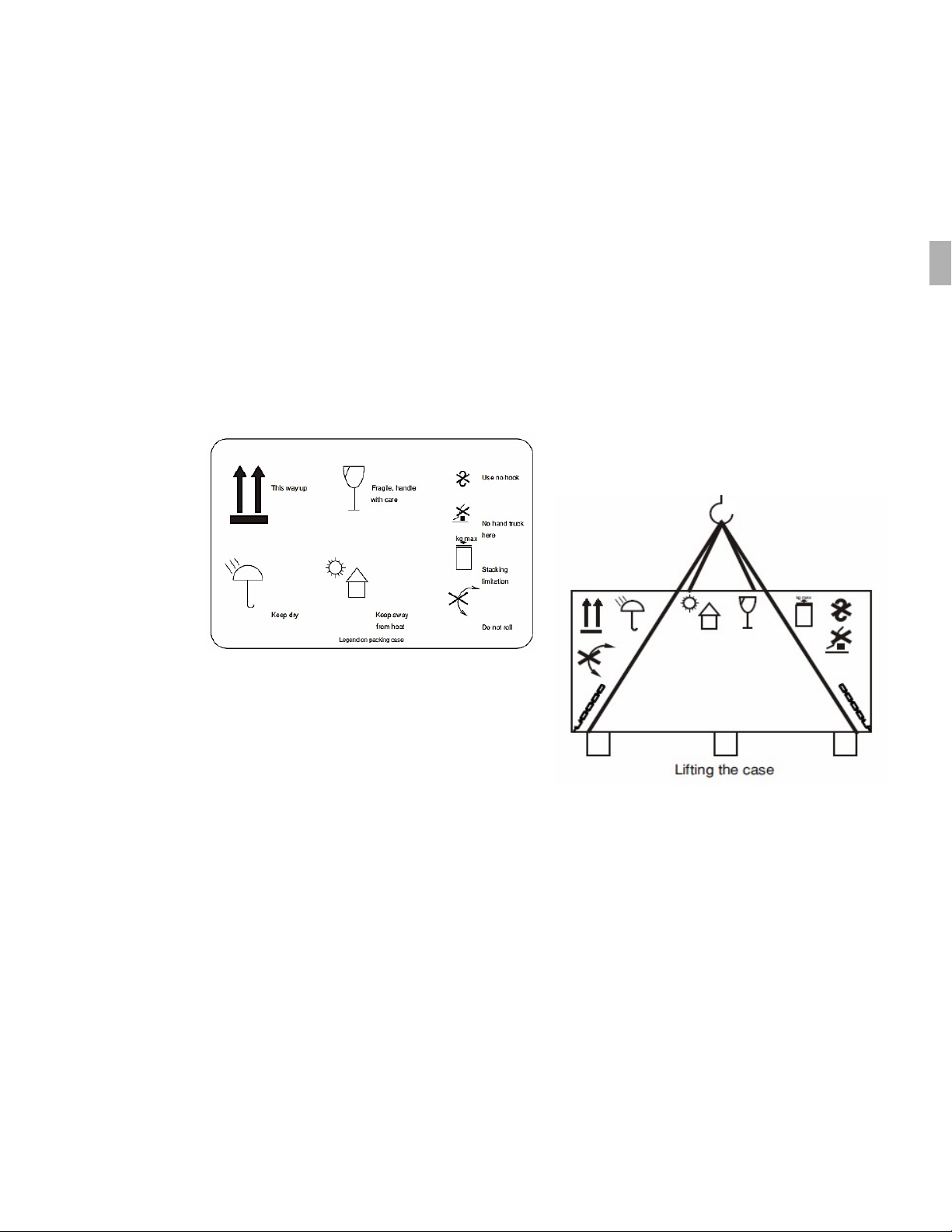
The LV cabinet with complete packing should
always be stored indoors to protect it from direct
sunlight, rain or snow. LV cabinets should be stored
in their original transport units, where they
are well protected from damage.
LV cabinets can be stored up to three months
from date of shipment from the factory. For longer
storage, the packing must be removed and the
recloser must be kept under controlled
environmental conditions.
We define storage in controlled conditions
as a location with:
• Leak-proof roof
• Solid, flat ground
• Relative humidity less than 50%
•
• The heating elements must be connected to the
electric supply to protect the control equipment
from corrosion or freezing damage.
IMPORTANT
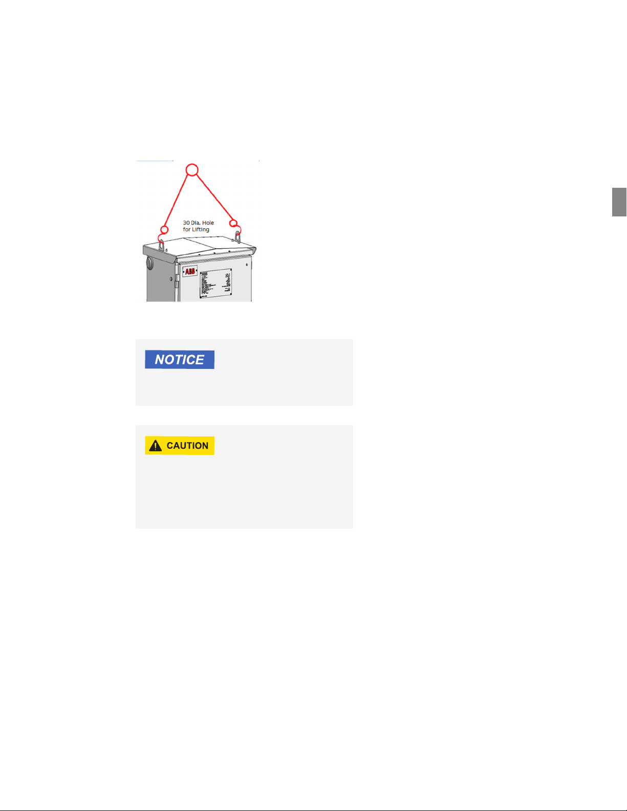
The LV cabinet must be stored in the upright
position to avoid moisture accumulation.
Recommended storage temperature range
The LV control cabinet has rechargeable
batteries inside. A periodic check of battery
voltage (24 V) and periodic charging of the
batteries (typically every three months) may
be required in case of prolonged storage.
For the batteries in your control cabinet,
refer to technical documentation of the
respective battery manufacturer. In addition,
refer to the “inspection and maintenance”
section of this manual for more information.
If the LV cabinet is not placed in service
immediately, it is essential that proper care be
exercised in handling and storage to ensure
good operating condition in the future. Please
consult ABB if the recloser will be in storage for
an extended period of time before installation.
03

9RECEIPT AND STORAGE PRIOR TO INSTALLATION
3.3 Handling
The LV cabinet comes with welded lifting brackets
on the sides of the cabinet for lifting. A four-point
lift using the loops in these brackets is highly
recommended The approximate mass in kg is
indicated on rating plates on HV and LV cabinets.
cabinets.
—
03
Exercise care during lifting to avoid damage
to the poles.
Do not place the recloser LV unit on an uneven
surface. Placing the LV unit on an uneven
surface may cause tilting/galling of the LV unit,
causing damage to the equipment and injuries
to nearby personnel.
—
03 LV Cabinet
lifting detail
03

B1 copy starts here
B2 copy starts here
B3 copy starts here
10 OVR-15, 27 AND 38 OUTDOOR VACUUM RECLOSER LOW VOLTAGE UNIT WITH SEL-751
—
4 General description of OVR-15, 27 and 38
recloser LV cabinet
4.1 LV cabinet assembly
Each OVR-15, 27 and 38 recloser LV cabinet has an
intelligent battery charger, capacitors, control
modules, relay and battery with their hard-wired
circuits. Please refer to the LV GA for other
constructional details.
4.2 Control
4.2.1 Low voltage control cabinet (LV cabinet)
A weatherproof, IP55-rated cabinet houses the low
voltage control components. The LV cabinet has
an outer hinged swinging door with padlocking
provision. The SEL-751 control and protection relay
is mounted on an inner hinged swinging door
to allow front and rear access to it. All the MCBs
and auxiliary power socket for laptop charging are
mounted on the front side of the inner swinging
door for easy operator access. Space for mounting
other devices, including optional radio modem, is
provided on the side/rear walls of the cabinet.
The LV cabinet floor is equipped with a removable
gland plate to provide entry for auxiliary power
cable and communication cables. A 50 W
thermostatically controlled heater is provided
to prevent condensation inside the LV cabinet.
4.2.2 Programmable battery charger
A programmable battery charger is included to
convert the auxiliary power supply connected from
an external PT or equivalent to a suitable form
required for components such as battery, SEL-751,
actuator control module (ACM) and external
communication modem, if applicable. Proper
handling is mandatory.
4.2.3 Auxiliary supply
The LV control cabinet requires auxiliary power
to operate the recloser, ACM, HV and LV cubicle
heating, illumination, etc. A separate outdoor type
2 x 1.5 sq. mm jacketed cable is required to connect
the external auxiliary power to the LV cabinet. See
the recloser quick reference guide for details.
—
04 LV control
cabinet overview
—
04
04

11GENERAL DESCRIPTION OF LV CABINET OF OVR-15, 27 AND 38 RECLOSER
For the auxiliary supply voltage/frequency
applicable for your recloser, please refer to
the approved/as-built drawings.
An MCB is provided inside the cubicle for protection
of the intelligent battery charger, cubicle heating,
illumination and auxiliary power socket outlet.
The auxiliary power outlet on the inner
swinging door is intended only for laptop
charging in an emergency. It should not be
used for any other purpose because it may
burden the external auxiliary power source.
4.2.4 Actuator control module
The actuator control module (ACM) gets its power
supply from the intelligent battery charger.
Hardwired to the SEL-751 relay, the ACM regulates
closing and tripping signals to the magnetic
actuator in accordance with feedback from the
HV unit and interaction with the relay by charging/
discharging the capacitors.
—
05
4.2.5 Rechargeable batteries
The LV unit is supplied with two 12 V batteries
connected in series and securely mounted in the
LV cabinet for providing backup power to the
recloser in case of external auxiliary power failure.
Typically, the battery bank ensures minimal
stand-by backup power for 24 hours at 20 °C from
a fully charged initial condition. However, the actual
backup duration depends upon various site
conditions, including:
• Ambient temperature and initial condition of the
battery (temperature and storage period before
commissioning, periodic charge/discharge,
battery maintenance)
• Frequency of external auxiliary power outages
and duration of each outage (i.e., the number
of charging/discharging cycles) and depth
of each discharge
• Percent charging (terminal voltage) of the battery
at the time of outage of external auxiliary power
For additional details, refer to the battery
manufacturer’s documentation. Also, see the
inspection and maintenance section of this manual.
A battery temperature sensor is provided near
the battery bank terminals. Battery charging
The batteries provided are valve-regulated lead
acid (VRLA) batteries, which are temperature and
charging voltage sensitive. Although maintenance
by way of water topping is not required, a regular
check and assurance of proper charging voltage,
depth of discharge and operating temperature
is needed.
In case of loss of external auxiliary supply, the
intelligent battery charger switches over to the
battery bank for power and continues to conduct
its function. The recloser will operate if the battery
bank voltage remains above 20.5 V. Below 20.5 V,
a load management algorithm activates within the
intelligent battery charger and disconnects the
power feed to the ACM, SEL-751 and optional radio
modem. The purpose of this is to delay the
batteries going into deep discharge mode. With
the relay not being powered, the recloser will not
be able to perform any operation.
—
05 Actuator control
module (ACM)
04
ACM LED status Description
1 2 3 4
OFF Blinking fast OFF OFF Normal condition — ACM ready
to perform operations
Blinking
slowly
Blinking fast OFF OFF Close operation is not allowed
ON Blinking fast OFF OFF Neither open nor close operations are
allowed
Any Blinking slowly Boot loader started, but FW is missing
ON OFF ON OFF File system error
OFF OFF ON ON Initial condition at start-up; if LEDs remain
in this condition, the CPI has not started
ON ON ON ON This state shows for three seconds,
indicating ACM can receive FW upgrades

B1 copy starts here
B2 copy starts here
B3 copy starts here
12 OVR-15, 27 AND 38 OUTDOOR VACUUM RECLOSER LOW VOLTAGE UNIT WITH SEL-751
4.2.6 External auxiliary supply status monitoring
In the event of loss of external auxiliary supply,
the programmable battery charger sends a signal
to the SEL-751 relay over an independent binary
input. Thus, the status of availability of external
auxiliary power to the LV unit can be monitored
remotely if communication setup is available.
4.2.7 SEL-751 control
The OVR-15, 27 and 38 recloser LV cabinet is
supplied with the microprocessor-based SEL-751
intelligent electronic device (IED).
In the SEL-751, all card slots connections are made
with terminal blocks that are affixed to the frame
of the IED. This is powered by the charging device.
—
06
Definite time setting of 0 ms shall not be used
with OVR-15/27/38.
—
07
• In the case of frequent and long duration
external power outages, the battery
frequently undergoes discharge and charge
cycles. This reduces battery capacity,
charging efficiency and overall service life.
• During consistent long duration outages,
the battery bank voltage may drop below 18 V
(9 V per battery), indicating battery may have
deep discharged and cannot be charged
again. At this point, the battery must be
completely replaced with a brand new, fully
charged, equivalent battery.
• Connection of any additional load to the
battery is strictly prohibited, and ABB will
not be liable for any adverse impact this can
cause to recloser performance, including
battery life.
Handling reclosers during long outages
1. If the battery bank is healthy and in fully
special attention is required if the power
outage is less than 24 hours in duration.
2. If a power outage lasts more than 24 hours
OR typically >10 CO operations after power
failure, then it is considered a long duration
power outage requiring special attention
to the batteries.
3. During long outages, the batteries may
become drained to such a level that they go
into deep discharge stage (i.e., battery bank
voltage goes below 18 V).
4. In this situation, the recloser will not be able
to recharge the batteries automatically and
external charging may be required. Such
a situation may also damage the batteries
permanently, thus requiring battery
replacement.
5. To avoid this, if a power outage is expected
to last more than 24 hours, disconnect the
batteries from the circuit at the beginning
of the outage. When the outage ends and
power resumes, reconnect the batteries
to the circuit.
6. If a power outage lasts more than a month,
charge the batteries externally at regular
intervals to ensure the battery bank voltage
is always higher than 21 V DC.
—
06 SEL-751 display screen
and front-facing LEDs
—
07 SEL-751 modules
04

13GENERAL DESCRIPTION, STANDARD PRODUCTION TESTS
—
5 Standard production tests
The OVR-15, 27 and 38 recloser LV cabinets are
tested thoroughly at the factory before shipping.
The standard factory production tests include:
1. Verification of wiring as per approved
wiring diagram
2. Electrical operation:
a. Close and open in local/remote modes
b. Overcurrent response and automatic
reclosing through primary injection
3. Functional checks of manual controls (K69) and
associated electrical and mechanical close block
4. Minimum trip and time-current test
5. No-load mechanical operation test
A standard routine test report with a summary
of results is shipped with the product as part
of the documentation package.
05

B1 copy starts here
B2 copy starts here
B3 copy starts here
14 OVR-15, 27 AND 38 OUTDOOR VACUUM RECLOSER LOW VOLTAGE UNIT WITH SEL-751
—
6 Installation
The OVR-15, 27 and 38 recloser LV unit can be
installed in a substation frame or pole-mounting
frame, or it can be mounted into a customer-
supplied structure. Regardless of the mounting
method, it is imperative that the LV unit be vertical,
leveled and securely fastened.
Before shipping from the factory, the OVR-15, 27
and 38 recloser LV control cabinets are tested as
part of a system. The HV unit and LV control cabinet
that were tested together must be installed
together as a set. The units must be properly
matched by the serial numbers listed on the rating
plates provided on each unit.
• All metal mounting frames and structures
must be commonly grounded to the
grounding grid at the installation site.
For proper operation of the electronic
components, the total impedance of the
grounding grid on site must be less than
• It is also mandatory to ensure that all
grounding connections to the welded star
grounding pad inside the LV cabinet are
always intact and secured.
• Be careful not to bend the cable beyond
a radius of 12 inches to avoid damage
to the cable.
6.1 Grounding
IMPORTANT
Always follow international, national, local and
company-specific regulations when grounding
the equipment.
All metal mounting frames and structures must be
commonly grounded to the grounding grid at the
installation site. Grounding is important to ensure
proper operation of all electronic components,
as well as to prevent penetration of EMC noise
and other transients into the sensitive electronic
circuits (SEL-751 relay, ACM, radios, etc.). Each
LV cabinet includes two stainless steel welded
grounding pads for grounding and an M8 stud
as shown in figure 8. For grounding, an 80 sq. mm
solid copper strip/equivalent is recommended.
For the proper operation of electronic components,
it is mandatory that the total impedance of the
It is also mandatory to ensure that all grounding
connections to the welded star grounding pad
inside the LV cabinet are always intact and secured.
Grounding terminal (M8)
—
08
—
08 Provisions for
grounding connections
on LV cabinet
06

15INSTALLATION
06
6.2 Connecting the HV and LV cabinets
by control cable
For normal operation, the HV and LV units are
required to be connected with a shielded control
cable. The control cable is supplied as per specified
length, with 24-pin connectors and locking clips
on both ends for connection to 24-pin connector
counterparts on the HV and LV cabinets.
1. Minimum bending radius for the control
cable is 12 inches. Bending the cable beyond
a 12-inch radius may damage the cable.
2. As a best practice, the control cable must
be clamped to the pole at regular intervals
along its length.
6.3 Connecting the auxiliary supply
The control cabinet requires an external two-wire
auxiliary supply. Please refer the approved/as-built
drawings for the auxiliary supply voltage/frequency
applicable to your recloser.
If specified during the ordering stage, an optional
auxiliary supply cable can be supplied with the
recloser. It is a black jacketed, 2 x 1.5 sq. mm
auxiliary power cable with a gland and nut on
one end to bring it inside the LV cabinet.
If the auxiliary control power is to be obtained
from a pole-mounted VT (PT), the power rating
of the VT (PT) should be a minimum of 250 VA.
Unless specified, ABB will not supply the VT (PT)
with the recloser.
• Before connecting the external auxiliary
power source to the LV cabinet, make sure
all MCBs on the inner swinging door are
switched off.
• Follow instructions on the warning label
provided on the inner swinging door panel.
6.4 Final inspections before energizing
The complete OVR recloser should be tested for
mechanical and electrical operation before it is
energized in the power system. Note that the
recloser is shipped in the OPEN (OFF) condition
from the factory.
Do not ground either side of the battery or
attach ground to the terminals of the actuator
operating coils. This will result in permanent
damage to the unit.
When both LV cabinet and HV cabinet are installed
completely with all mechanical and electrical
connections completed, conduct the following
mandatory inspection before energizing the
recloser on the main lines.
1. Ensure the LV cabinet is properly leveled
and securely anchored.
2. Recheck the tightness of all hardware.
3. Securely tighten terminals and ground
connections.
4. Check that the control cable is properly
connected, routed and secured.
5. Ensure that both the HV and LV cabinets
are grounded as described in this manual.
—
09 Control cable
connection to HV cabinet
—
10 Control cable
connection to LV cabinet
—
09
—
10

B1 copy starts here
B2 copy starts here
B3 copy starts here
16 OVR-15, 27 AND 38 OUTDOOR VACUUM RECLOSER LOW VOLTAGE UNIT WITH SEL-751
6.5 Table 2: Operating procedure
Initial conditions at the time
of shipping
• Recloser interrupter contacts in OPEN (OFF) condition.
• All MCBs in LV cabinet in OFF position.
• Battery physically disconnected from main circuit.
Preparation before
powering ON
(PT), etc.
that all male/female connections are firmly secured on both the HV and LV units.
is released.
To power ON the LV cabinet
with auxiliary power
Check wiring diagram provided in order bound drawings.
and controlled by door limit switch) should glow.
To connect auxiliary supply
to charging device and ACM
• Switch ON the MCB dedicated to the external charger and AC circuits.
• With auxiliary power ON, the thermostatically controlled heaters in the HV and LV
cabinets may also turn ON.
To connect batteries
to charging device
circuit. Check schematic diagram supplied with the documents for details.
If a radio modem is provided
or added later on site, follow
these instructions to power
it ON
If a radio modem is factory supplied with the recloser, it will come already wired to the
radio modem MCB. Switch ON this radio MCB to power it ON. Check and connect the
hardwired connection between relay and radio modem. Otherwise, to connect a separately
procured radio modem on site, follow these steps:
of suitable rating in the circuit.
the communication protocol. The modem antenna can be connected outside the LV box
by routing the antenna wire through the LV box’s bottom gland plate.
Observations when
ACM power is ON
When the AC MCB of the charging device is turned on:
• ACM will conduct internal tests initially with both RED and GREEN LEDs blinking. It may
take about two minutes for the recloser to become ready from each initial energization.
• Successful energization will be indicated by the GREEN LED becoming steady and red
LED continuously OFF. This indicates that the ACM (recloser) is ready for operation.
• The SEL-751 relay (on inner swinging door) is fully powered up when the LCD screen
and LEDs on its HMI are fully lit.
AR Ready indication
on relay LED
When the ACM completes all internal tests and fully charges the capacitors, the “AR Ready”
(Please refer to the approved/as-built wiring diagram for a detailed description of the SEL-
CLOSE operation To close the recloser:
• Confirm the emergency manual trip (K69) handle is reset.
• Confirm the recloser status as OPEN by referring to relay HMI (dedicated LED) and the
ON/OFF position indicator on HV unit.
• Press the CLOSE button on relay HMI to close the recloser.
OPEN operation To open/trip the recloser:
• Confirm the recloser status as CLOSED by referring to relay HMI (dedicated LED) and the
mechanical ON/OFF indicator on HV unit.
• Press the OPEN button on relay HMI to open the recloser.
06

17INSTALLATION, INSPECTION AND MAINTENANCE
—
7 Inspection and maintenance
The OVR-15, 27 and 38 LV unit will require minimal
maintenance if handled properly. The frequency
of operation and local environmental conditions
should be considered when determining a
maintenance schedule.
To a large extent, the safety and successful
functioning of any apparatus or system connected
with the recloser depends on the proper
installation, commissioning, programming and
configuration of the unit.
To provide long, reliable service, the LV unit should
be inspected at regular intervals. Operating
experience, environmental conditions, the number
of operations and any unusual service conditions
should guide you in establishing a maintenance
schedule.
Maintenance work must only be carried out by
trained personnel who know and respect all safety
regulations. In addition, it is recommended that
ABB service personnel should be called in to check
the service performance and for repair work.
7.1 Activities before performing any maintenance
on the recloser LV unit
(Perform this in conjunction with instructions in the
HV unit instruction manual.)
1. OPEN the recloser with the emergency manual
trip (K69) handle. This enables the mechanical
as well as electrical block close (recloser cannot
be closed unless the K69 handle is manually
reset).
2. Confirm the recloser OPEN status on the SEL-751
relay HMI and on the mechanical ON/OFF
indicator on the HV cabinet.
3. Switch OFF all MCBs to disconnect AC auxiliary
power and battery backup. This will connect the
capacitors to the discharge circuit.
4. Wait until the capacitors are discharged to a
safe level (when the RED LED on the discharge
circuit stops glowing).
5. Thus, all the electrical controls/measurements
and protections/communications of the
recloser are switched OFF, and the recloser LV
cabinet is ready for maintenance.
7.2 Additional activities before performing any
maintenance on the recloser LV unit
1. Complete all activities described in section 7.1.
2. Ensure that the main circuit is properly
grounded.
3. Follow all safety practices required by national
and local codes as well as company policies.
7.3 Removal of the SEL-751 relay
Once the SEL-751 relay is powered OFF, open the
inner door. Remove the connector with wiring.
Loosen the four screws from the back of the relay.
Gently remove the relay and gasket.
7.4 Removal of batteries
Adhere to the mandatory safety procedures as
outlined in section 1.0 of this document. Follow
the steps outlined below if required to remove
the batteries.
Before physically removing the batteries from the
LV unit, ensure that the battery MCB is OFF and the
battery connections are completely removed from
battery terminals.
1. Switch off the battery MCB.
2. Disengage male/female in the battery circuit.
3. Remove the M6 hex head screws A, B and C.
4. Remove the battery temperature sensor by
disengaging the male/female connectors.
5. Remove the entire battery assembly and then
remove the clamps by removing M6 hex head
screws D and E.
6. Remove batteries B1 and B2 in the direction
shown in figure 11.
07

B1 copy starts here
B2 copy starts here
B3 copy starts here
18 OVR-15, 27 AND 38 OUTDOOR VACUUM RECLOSER LOW VOLTAGE UNIT WITH SEL-751
—
11 Removal of batteries
—
11
07

19INSPECTION AND MAINTENANCE, COMMON ISSUES AND TROUBLESHOOTING
—
8 Common issues and troubleshooting
—
Table 3: Troubleshooting chart for OVR reclosers
(Please use this table in conjunction with the approved/as-built wiring diagram.)
No. Trouble/malfunction Indication/observation Possible causes Remedy/troubleshooting
Auxiliary power failure No voltage across auxiliary
supply terminals in LV unit
• External auxiliary power
connection to LV unit is
loosely connected
• External auxiliary power
may be OFF
• Properly connect the
auxiliary power supply
cable to the terminal
connectors inside
the LV unit
• Check and correct the
status of the external
power supply
Voltage is present across
auxiliary power terminals in
LV unit, but cubicle light and
auxiliary power outlet,
heater(s), do not have power
Auxiliary supply mains
MCB is OFF
Switch ON the MCB for
auxiliary supply mains
power up even after main
auxiliary MCB is ON and
auxiliary supply is available
Charging device is defective
(its LED is not glowing
continuously)
If LED is not glowing Charging device is defective;
consult ABB representative
None of the LEDs
(RED/GREEN) on ACM glow
MCB for ACM is OFF Switch ON MCB for ACM
HMI glow and LCD
screen does not light up
Recloser (AR) is NOT ready;
OPEN and CLOSE operations
or from remote
One or more blinking RED
LEDs on ACM
Manual lock-out activated;
emergency manual trip
operated and is locked in
operated/tripped position
Reset the emergency manual
trip handle and release the
manual lock-out
AR Ready LED on relay
glowing RED
Control cable between LV
and HV units is loose or not
connected
Connect and secure the
control cable between the
HV and LV units
Capacitors not sufficiently
charged
• Turn off DC supply MCB
and allow capacitors to
fully discharge (follow
warning label text
guidelines)
• Check capacitor
connections to ACM for
loose contact and correct
polarity as per wiring
diagram
• Check the capacitor
health; replace capacitors
if needed
Wrong recloser ON/OFF
(mismatch with mechanical
ON/OFF indicator/ LEDs
-OR-
Relay LED or SLD on relay
LCD shows both ( ON/OFF)
or no status
auxiliary limit switch may
auxiliary limit switch is
mounted in HV unit)
Check, secure and correct
limit switch as per approved
/as-built schematic
The mounting/setting of the
may be wrong or loose
-OR-
switch is faulty/ damaged
is mounted in HV unit)
• Check and correct the
mounting/setting of the
52a/b auxiliary limit
switch
• Replacement of the 52a/b
switch may be needed if
found to be faulty/
damaged
• Contact ABB Customer
Service Group
08

B1 copy starts here
B2 copy starts here
B3 copy starts here
20 OVR-15, 27 AND 38 OUTDOOR VACUUM RECLOSER LOW VOLTAGE UNIT WITH SEL-751
No. Trouble/malfunction Indication/observation Possible causes Remedy/troubleshooting
Recloser (AR) is ready,
but CLOSE operation is
local HMI or remote
SYN CHECK LED
(if applicable) on relay
HMI turns RED
The phase sequence of the
MV power connections on
both sides of the recloser
do not match each other
Check and correct the phase
sequence of the MV power
cable connections to the
recloser terminals
Synchronizing and
energization check
conditions are not being
satisfied as per settings
of SECRSYN function block
Check system voltage
parameter and
network status
Battery failure Battery status
LED on relay HMI
turning RED
MCB for battery is OFF Switch ON the MCB
for battery
Battery connections to
charging device are loose
or have wrong polarity
Check, correct and secure
battery connections to
charging device with
correct polarities
Battery unhealthy (battery
may have undergone deep
discharge or excessive
temperatures or exceeded
working life)
Check battery health
and replace the battery
if needed
Condition monitoring
alarm activated
(This is a proactive alarm
about a recloser condition
that may require attention
in the near future)
Condition monitoring
alarm on relay HMI
turning RED
Out of the rated life of
operations remain
Contact the nearest ABB
Customer Service Group
for further advice
Recloser has completed
a greater number of open
operations on higher
currents (fault currents)
Recloser is in inactive
(no close/open operations)
days; after the latest ON/
OFF operation while LV unit
powered ON
08
Other manuals for OVR-15
4
This manual suits for next models
2
Table of contents
Other ABB Industrial Equipment manuals
Popular Industrial Equipment manuals by other brands

ETP Transmission
ETP Transmission HYDRO-GRIP GE2 Operating instruction

schmersal
schmersal AZM300Z-I1-ST-1P2P-A Instructions for operation

Conductix-Wampfler
Conductix-Wampfler R Series Installation, operation & maintenance manual

Grizzly
Grizzly T33850 owner's manual

Berker
Berker RolloTec 2911 operating instructions

GF
GF GF 500 operating instructions