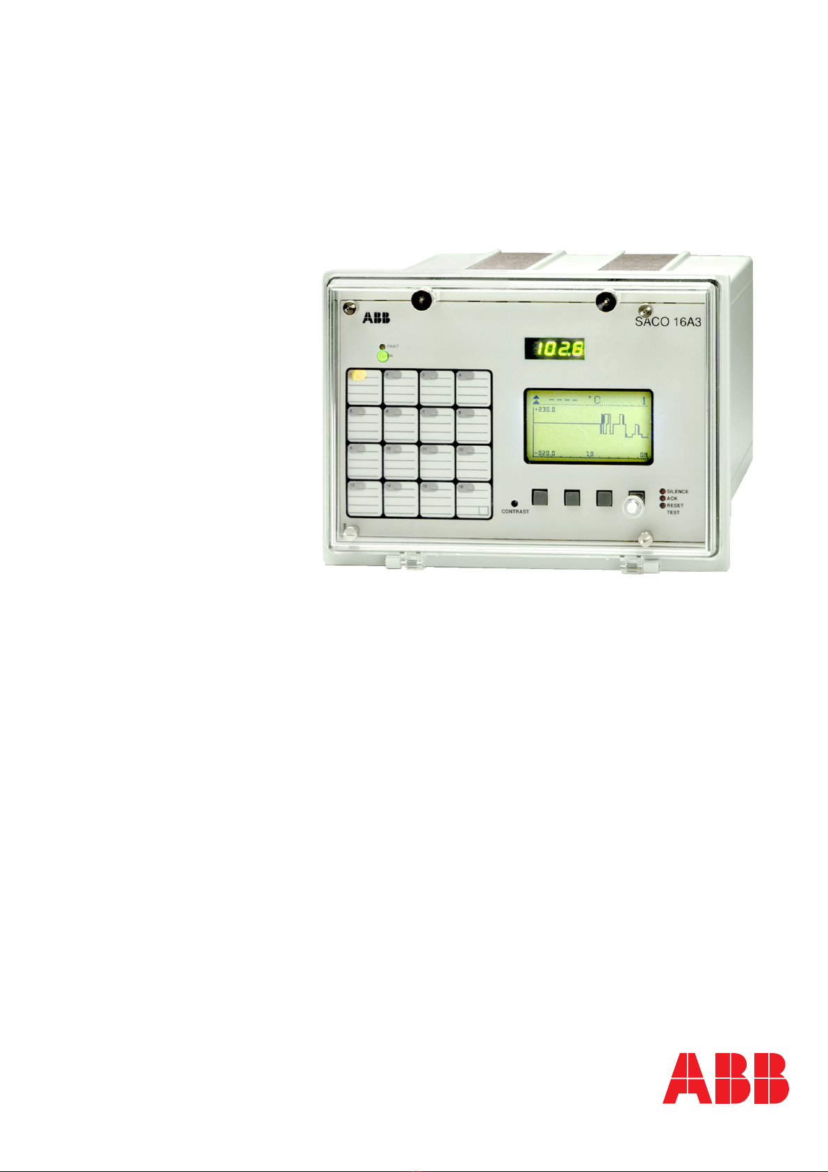
Analog Annunciator Unit
Product Guide
SACO 16 A3
1MRS750405-MBG
4
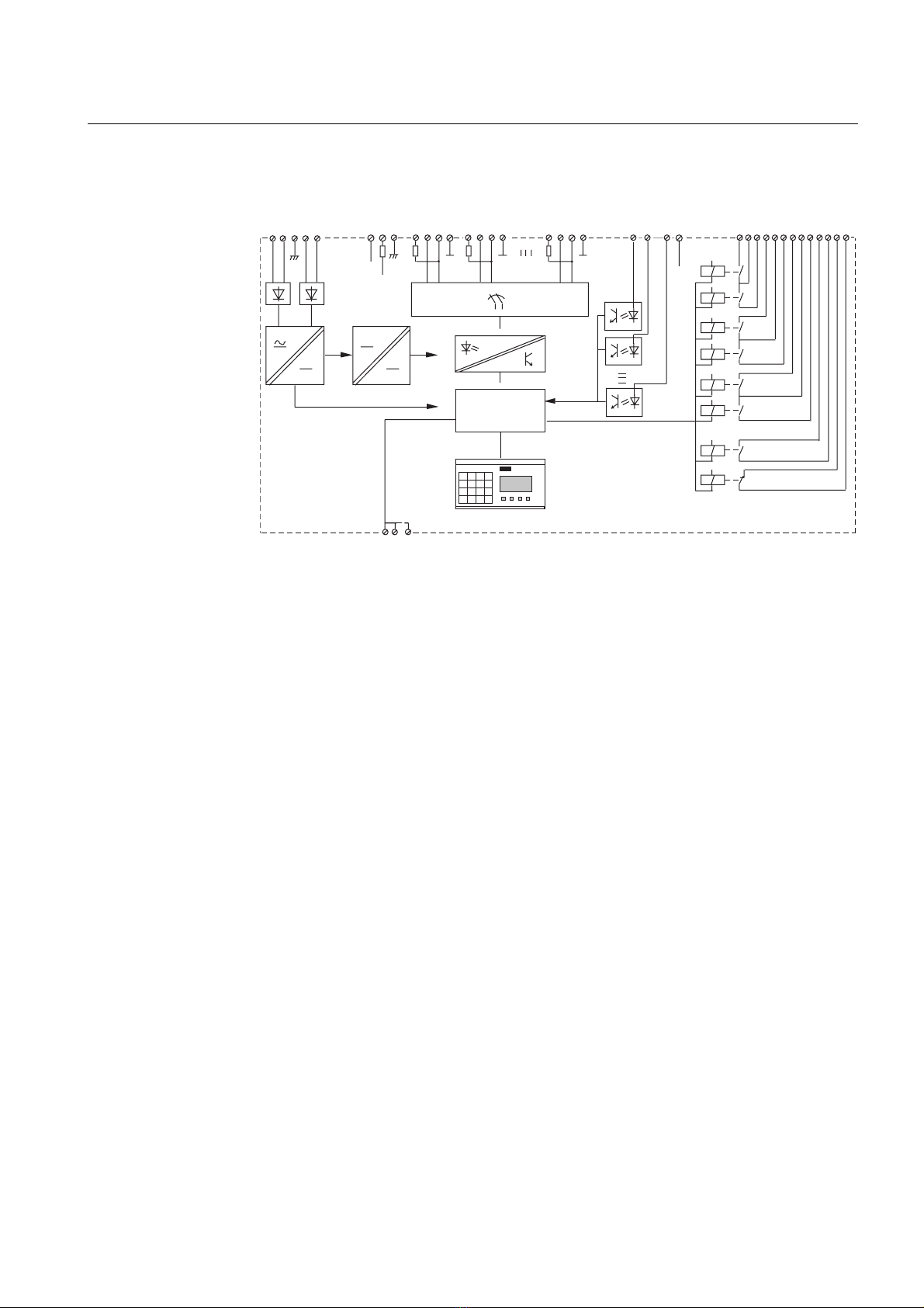
Design The channels of the analog annunciator unit
measure voltage, current and resistance via
sensors or transducers in the process. Further,
contact signals can be wired to the input
channels. The signal type can be separately
set for each channel.
The channel inputs are galvanically separated
from earth and from the digital part of the
annunciator electronics, but the channels are
galvanically interconnected. This arrange-
ment facilitates the supervision and the indi-
cation of earth faults in the transducers or the
transducer wiring.
The alarm channel inputs accept the follow-
ing signal levels: 0…5 mA, 1…5 mA,
0…20 mA and 4…20 mA, 0…1 V, 0…5 V,
1…5 V, 0…10 V and 2…10 V. The following
standard sensors types can be used for tem-
perature measurement: Pt 100, Pt 250,
Pt 1000, Ni 100, Ni 120, Ni 250, Ni 1000.
Further, any Pt or Ni signal within the range
65…1000 Ω, potentiometric signal within the
range 0…200 Ω, 0…500 Ω, 0…1 kΩ,
0…2 kΩ, 0…2.5 kΩ, 0…10 kΩcan be used
and scaled. For the resistance sensors two- or
three-wire connection can be used.
In addition, the input channels can be acti-
vated by a making or a breaking contact.
The values measured can be shown as numer-
ical values, bar graphs or curves on the dot
matrix display on the front panel. The same
information can also be read by a superior
system via the serial interface.
The content of the event sequence register
can be read on the display. The total system
can be configured by means of the push-but-
tons and the display on the front panel, or via
the serial interface.
When a measured signal exceeds or falls
below the set start value of the channel a
visual indication is obtained on the alarm
panel. At the same time the acoustic alarm
output contact picks up and, if configured, a
group alarm relay operates. The event thus
generated is stored in the event register.
Any information generated in the annunciator
unit can be read by a hierarchically superior
system via the serial interface.
Data communication
The relay is provided with a serial interface
on the rear panel. By means of a bus connec-
tion module type SPA-ZC 17/S or SPA-
ZC 21/S the relay can be connected to the
fibre-optic SPA bus. The bus connection
module type SPA-ZC 21/S is powered from
the host relay, whereas the bus connection
module SPA-ZC 17/S is provided with a
built-in power unit, which can be fed from an
external secured power source. The relay
communicates with higher-level data acquisi-
tion and control systems over the SPA bus.
Self-supervision
The annunciator incorporates a sophisticated
self-supervision system which increases the
availability of the device and the reliability of
the system. The self-supervision system con-
tinuously monitors the hardware and the soft-
ware of the equipment. The system also
supervises the operation of the auxiliary sup-
ply module and the electronics’ voltages gen-
erated by the module.
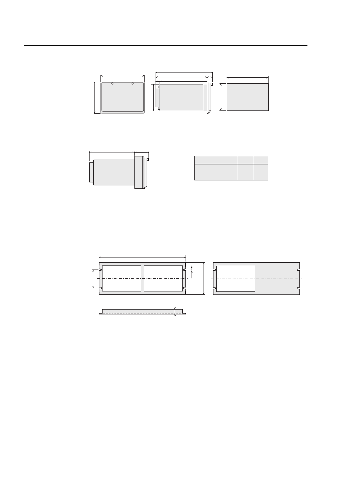
Auxiliary supply voltage
The auxiliary supply of the relay is obtained
from an internal plug-in type power supply
module. Two auxiliary power module ver-
sions are available: type SPGU 240A1 for the
supply voltage range 80…265 V ac/dc and
type SPGU 48B2 for the supply voltage range
18…80 V dc. The power supply module
forms the internal voltages required by the
annunciator.