ABB CM-TCN User manual

PREPARED
2021-04-09
STATUS
Approved
SECURITY LEVEL
Public
APPROVED
2021-04-20
DOCUMENT KIND
Manual
OWNING ORGANIZATION
ABB STOTZ-KONTAKT GmbH
DOCUMENT ID.
2CDC112285M0201
REV.
B
LANG.
en
PAGE
1/42
© Copyright 2020 ABB. All rights reserved.
—
MANUAL
Smart Temperature Monitoring Relays
CM-TCN

SMART T EMP ER AT URE MO NITORING REL AYS
STATUS
Approved
SECURITY LEVEL
Public
DOCUMENT ID.
2CDC112285M0201
REV.
B
LANG.
en
PAGE
2/42
© Copyright 2020 ABB. All rights reserved.
Important notice, purpose and basic description
These manual supplements our product catalog and provides the general func-
tionality as well as application suggestions for our smart temperature monitoring
relays. For additional technical data please refer to our catalogue or contact us.
You can either read the entire manual or selectively gather information about in-
dividual devices and their possible applications.
The table of contents and the index section enable quick and easy access to the
desired information.
Target group
This description is intended for use by trained specialists in electrical installation
and control and automation engineering, who are familiar with the applicable na-
tional standards.
Safety requirements
The responsible staff must ensure that the application or use of the products de-
scribed satisfy all the requirements for safety, including all the relevant laws, reg-
ulations, guidelines and standards.
Symbols
This technical document contains markers to point the reader to important infor-
mation, potential risks and precautionary information the following symbols are
used:
Indicates a potentially dangerous situation that can cause damage to
the connected devices or the environment.
Indicates important information and conditions.
Indicates a potentially dangerous situation that can cause human inju-
ries.
Abbreviations
NFC Near Field Communication
EPiC Electrification Products intuitive Config-
urator
CM-TCN Temperature monitoring relay
Related Documents
2CDC112286C2010 CM-TCN catalog
1SVC750040M0000 Installation instructions

SMART T EMP ER AT URE MO NITORING REL AYS
STATUS
Approved
SECURITY LEVEL
Public
DOCUMENT ID.
2CDC112285M0201
REV.
B
LANG.
en
PAGE
3/42
© Copyright 2020 ABB. All rights reserved.
Contents
1. Device overview .......................................................................................................................... 5
1.1. LCD display and symbol-based menu structure ...................................................................5
1.2. Near Field Communication (NFC) ........................................................................................... 6
1.3. Device description ....................................................................................................................... 7
2. Installation.................................................................................................................................. 8
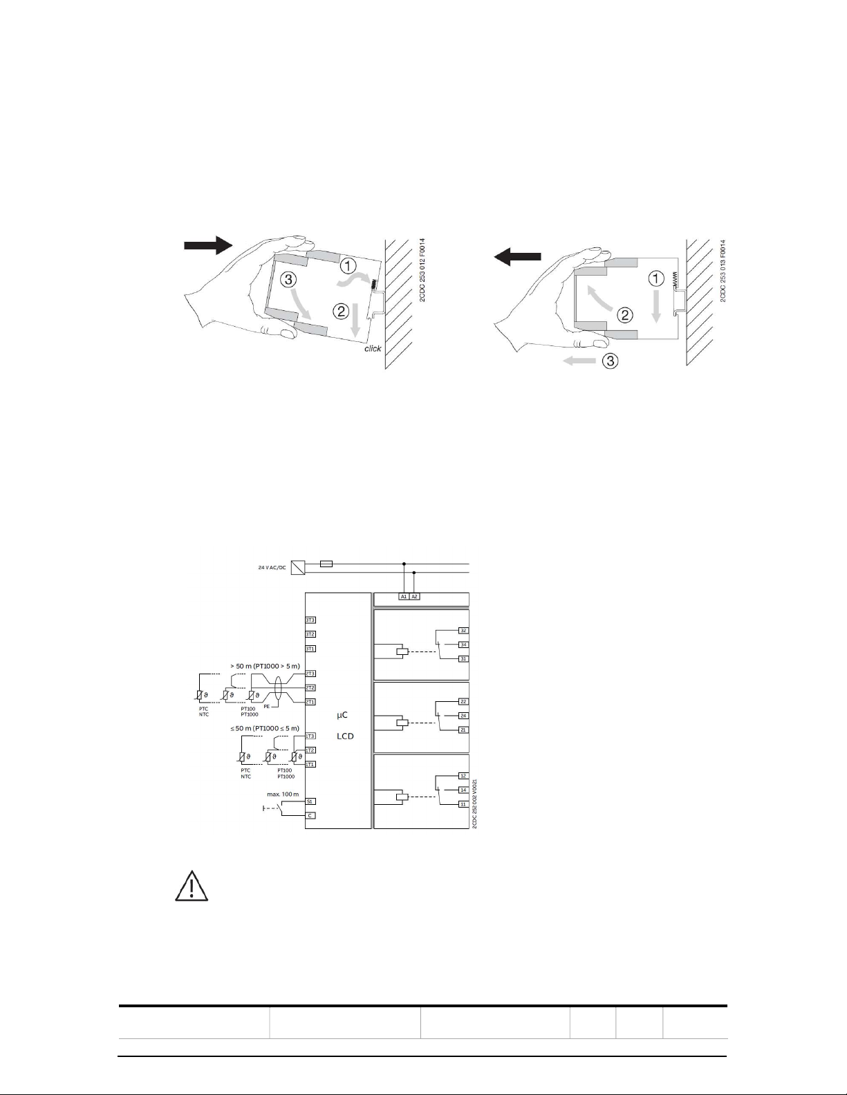
2.1. Mounting and de-mounting ..................................................................................................... 8
2.2. Block diagram .............................................................................................................................. 8
2.3. Sealable transparent cover ....................................................................................................... 9
3. Commissioning ......................................................................................................................... 10
The smart temperature relays are configurable in two ways: ..................................................... 10
- The first option is via the LCD and the push-rotate button on the front
of the device. .............................................................................................................................. 10
- The second option is to use the EPiC smartphone app.................................................... 10
In the next sections the configuration via LCD and push-rotate button is
explained. ..................................................................................................................................... 10
3.1. Main screen ................................................................................................................................. 10
3.2. Menu navigation......................................................................................................................... 11
4. Configuration and setup .......................................................................................................... 12
4.1. Factory profiles .......................................................................................................................... 12
4.1.1. Factory 1 - Motor protection with PT100 sensors ............................................ 14
4.1.2. Factory 2: Motor bearing supervision with PT100 ........................................... 15
4.1.3. Factory 3: Motor supervision with PT100 – 2 ..................................................... 16
4.1.4. Factory 4: Motor winding supervision with PTC ............................................... 17
4.1.5. Factory 5: Transformer supervision with PT100 ............................................... 18
4.1.6. Factory 6: Transformer supervision with PTC ................................................... 19
4.1.7. Factory 7: Individual temperature supervision with PT100 ........................... 20
4.2. User profiles and individual parameterization ................................................................... 21
4.2.1. Step 1: Sensor configuration ................................................................................. 21
4.2.2. Step 2: Signal definition .........................................................................................22
4.2.3. Step 3: Relay assignment and configuration .................................................... 26
4.2.4. Save configuration into user profiles ................................................................. 29
5. Security ..................................................................................................................................... 30
5.1. Parameter lock........................................................................................................................... 30
5.2. Password protection ................................................................................................................. 31
5.3. Near Field Communication ..................................................................................................... 32
6. Error handling, maintenance and service ............................................................................... 33
6.1. Additional functions ................................................................................................................ 33
6.1.1. Display ON-time ...................................................................................................... 33
6.1.2. Temperature unit .................................................................................................... 34
6.1.3. Power-on delay ........................................................................................................ 34
6.1.4. User-defined text .................................................................................................... 35
7. Condition monitoring ...............................................................................................................36
7.1.1. Event history ............................................................................................................. 37
7.1.2. Operating hour counter ......................................................................................... 38
7.1.3. Maintenance counter .............................................................................................. 38
7.1.4. Statistics ................................................................................................................... 39
7.1.5. Password reset counter ......................................................................................... 39

SMART T EMP ER AT URE MO NITORING REL AYS
STATUS
Approved
SECURITY LEVEL
Public
DOCUMENT ID.
2CDC112285M0201
REV.
B
LANG.
en
PAGE
4/42
© Copyright 2020 ABB. All rights reserved.
7.1.6. Simulation mode ..................................................................................................... 39
7.1.7. QR-code ..................................................................................................................... 40
7.1.8. Factory reset ............................................................................................................ 40
7.1.9. Device information .................................................................................................. 41

SMART T EMP ER AT URE MO NITORING REL AYS
STATUS
Approved
SECURITY LEVEL
Public
DOCUMENT ID.
2CDC112285M0201
REV.
B
LANG.
en
PAGE
5/42
© Copyright 2020 ABB. All rights reserved.
1. Device overview
The CM-TCN smart temperature monitoring relay aims to meet different cus-
tomer needs with just one device. The LCD screen provides status updates with a
single glance. Near Field Communication (NFC) enables to adjust settings with
one touch of a smartphone, making installation faster and more intuitive.
The device comes with a wide measuring range from -200…+850 °C and is com-
patible with multiple sensor types, as well as predefined settings for common
motor or transformer supervision applications and storage space for user-de-
fined settings.
With the ABB EPiC app wireless configuration and status checks are easily possi-
ble. By using the app parameter settings can be edited quickly, stored in the app
or copied to other CM-TCN devices, even in an unpowered state. Moreover, pa-
rameters can be uploaded into a cloud or shared within seconds e.g. via E-mail.
The temperature monitoring relays are typically used in the following applica-
tions:
- Motor and system protection
- Temperature monitoring in
control cabinets
- Monitoring of electronic mo-
tors
- Monitoring of transformers
- Ambient temperature moni-
toring
- Temperature limits for pro-
cess variables
- Monitoring of bearing tem-
peratures
- Monitoring of cooling liquids
- Packaging industry
- Air Conditioning Systems
- Ventilation systems
- Heat pumps
- Hot water supplies
1.1. LCD display and symbol-based menu structure
Variants with LCD display are available. The display:
- Allows the intuitive and fast configuration with the help of a symbol-
based menu structure. Profiles are available for various applications. Each
parameter can also be modified individually and stored as a user profile
for later reuse.
- Shows permanently the device status and all currently measured temper-
atures. Detailed diagnosis information helps to identify problems quickly.
- Provides access to various service counters helping to reduce mainte-
nance cost
Symbols are used instead of text throughout the whole menu structure.

SMART T EMP ER AT URE MO NITORING REL AYS
STATUS
Approved
SECURITY LEVEL
Public
DOCUMENT ID.
2CDC112285M0201
REV.
B
LANG.
en
PAGE
6/42
© Copyright 2020 ABB. All rights reserved.
1.2. Near Field Communication (NFC)
Every device of the smart monitoring relay family is equipped with an NFC an-
tenna. This enables the parametrization of the devices with the ABB EPiC Mobile
smartphone app via NFC.
To read or write data the smartphone needs to touch the surface of the CM-TCN.
The connection is only active when the data transmission takes place. Contrary to
e.g. Bluetooth there is no constant communication to the device.
NFC is an international transmission standard based on radio-fre-
quency identification technology for the contact-less exchange of
data. This technology is already integrated in most electronic de-
vices like tablets and smartphones and part of everyday life, e.g.
for contactless payment.
The CM-TCN can be configured powered or without power sup-
plied. This simplifies pre-configuration of devices for customers
and helps optimize workflows.
ABB EPiC smartphone app
EPiC means “Electrification Products intuitive Configurator” and is the mobile ap-
plication that allows to configure and check the status of the ABB low voltage
products. The app is available for free and can be downloaded for Android and
iOS. Registration with a user account is mandatory.

SMART T EMP ER AT URE MO NITORING REL AYS
STATUS
Approved
SECURITY LEVEL
Public
DOCUMENT ID.
2CDC112285M0201
REV.
B
LANG.
en
PAGE
7/42
© Copyright 2020 ABB. All rights reserved.
1.3. Device description

SMART T EMP ER AT URE MO NITORING REL AYS
STATUS
Approved
SECURITY LEVEL
Public
DOCUMENT ID.
2CDC112285M0201
REV.
B
LANG.
en
PAGE
8/42
© Copyright 2020 ABB. All rights reserved.
2. Installation
2.1. Mounting and de-mounting
Snap-on mounting onto a 35 mm standard mounting rail, without using any tool.
Mounting De-mounting
2.2. Block diagram
The following block diagram shows the set-up of the CM-TCN: supply voltage
range, connection of sensor types, control input, function of output relays and
the galvanic insulation. For sensors the maximum cable length with a shielded
cable is 500 m.
In UL applications a fuse protection for the supply circuit is required.

SMART T EMP ER AT URE MO NITORING REL AYS
STATUS
Approved
SECURITY LEVEL
Public
DOCUMENT ID.
2CDC112285M0201
REV.
B
LANG.
en
PAGE
9/42
© Copyright 2020 ABB. All rights reserved.
2.3. Sealable transparent cover
To protect the relay against unauthorized access and usage, a transparent seal-
able cover can be used. The cover is available as an accessory.
Before mounting the sealable cover, the standard marker label must be removed
from the device and the mounting clip which is delivered together with the seal-
able cover must be snapped onto the device. After mounting the relay can be pro-
tected by a seal.

SMART T EMP ER AT URE MO NITORING REL AYS
STATUS
Approved
SECURITY LEVEL
Public
DOCUMENT ID.
2CDC112285M0201
REV.
B
LANG.
en
PAGE
10/42
© Copyright 2020 ABB. All rights reserved.
3. Commissioning
The smart temperature relays are configurable in two ways:
- The first option is via the LCD and the push-rotate button on the front of
the device.
- The second option is to use the EPiC smartphone app.
In the next sections the configuration via LCD and push-rotate button is
explained.
3.1. Main screen
On the main screen the most important information is provided to oversee the
status of the device. The main screen is divided in four sections, each containing
a different set of information.
Section one displays the measured temperature in each measuring circuit (chan-
nel). Each channel is displayed by the symbol for channel with a number cor-
responding to the number of the measuring circuit e.g. channel 1 equals measur-
ing circuit 1T1/1T2/1T3.
In section two the relay status is displayed. Through the symbol the actual sta-
tus of the relay can be determined immediately: a white relay means the relay is
deenergized and a filled-out symbol equals energized. The relays are numbered
according to the numbers on the terminal e.g. relay 1 equals terminal assignment
11/12/14.
Section three provides information regarding configurations which deviate from
the default e.g. cyclic switching function running or simulation mode selected. In
this case the symbol for e.g. cyclic switching function is shown here. This section
is also used in case of a relay trip to display the trip information per channel.
In case more than one trip is active, the information switches in a rhythm of 5
seconds between relays. The relay whose status is displayed will be framed. To
view the trip reason for a specific relay the user can enter section two and rotate
between the relays to display the needed value or to reset a trip in case manual
1
4
2
3
Frame around relay 1
Trip reason for relay 1:
overtemperature
>175 °C at channel 3

SMART T EMP ER AT URE MO NITORING REL AYS
STATUS
Approved
SECURITY LEVEL
Public
DOCUMENT ID.
2CDC112285M0201
REV.
B
LANG.
en
PAGE
11/42
© Copyright 2020 ABB. All rights reserved.
reset is selected. With a rotate action section 2 will be entered. A frame will be
displayed around the first relay and the trip reason for this relay will be displayed
in the bottom line.
The device offers two reset options: automatic and manual reset. To reset a relay
manually when manual reset is enabled the push-rotate button needs to be
pressed when the frame is around the relay which should be reset.
The reset screen will open:
By clicking on a reset is conducted. To abort the reset and go back to the start
screen needs to be selected.
Default setting for all relays is automatic reset. In this case the re-
set menu will not be displayed. If manual reset is configured for a
relay, the reset menu will become available automatically. The re-
lay detects if the reset condition is reached. In case it is not
reached the reset menu will not be available.
Example: In the picture displayed above, channel 1 shows a measured temperature
of 180.6 °C. Navigating the frame to relay 1 shows that it has tripped because the
configured threshold for overtemperature monitoring at 175 °C at channel 3 has
been reached.
Section 4 is used for devices with Modbus only. Here a symbol signalizes the work-
ing Modbus communication.
3.2. Menu navigation
The operation of the device as well as the configuration is done via a push-rotate
button which allows a precise menu navigation and accurate setting of any value.
The encoder can be operated either with a screwdriver or with the delivered knob
which fits in into the screwdriver fitting.

SMART T EMP ER AT URE MO NITORING REL AYS
STATUS
Approved
SECURITY LEVEL
Public
DOCUMENT ID.
2CDC112285M0201
REV.
B
LANG.
en
PAGE
12/42
© Copyright 2020 ABB. All rights reserved.
As soon as the relay is powered, the LCD lights up and the start screen shows the
currently measured values. The menu is entered with a push on the push-rotate
button. Through the rotation to the left or to the right the menu can be navigated.
To enter a submenu the respective symbol must be selected. The values of the
parameters can be selected through push-rotate actions. The set value becomes
active immediately after confirmation. To exit a menu the back symbol can be
used or pushing the push-rotate encoder for 2 s.
The display goes back to the main screen if no user interac-
tion is detected within 30 s. The current setting remains un-
changed.
4. Configuration and setup
This section provides information how to configure the CM-TCM temperature
relay with the help of profiles. There are two different profile categories – Fac-
tory and user profiles. The following sections will explain each option and how
to select and modify them.
The following parameters can be set:
Menu
Parameter
Symbol
Explanation
Data ran
ge
Profiles
Factory
profiles
One of seven profiles can be
selected for immediate use or
for optimized configuration
[yes, no]
User profiles
The user can save individual
parameter sets in one of four
user profiles
[yes, no]
Conducting a factory reset will delete the saved user profile
configurations.
4.1. Factory profiles
Factory profiles are parameter sets which offer default values for each parame-
ter, covering the most common applications like e.g. motor or transformer mon-
itoring and protection. These profiles allow a quick setup of the CM-TCN.

SMART T EMP ER AT URE MO NITORING REL AYS
STATUS
Approved
SECURITY LEVEL
Public
DOCUMENT ID.
2CDC112285M0201
REV.
B
LANG.
en
PAGE
13/42
© Copyright 2020 ABB. All rights reserved.
Factory profiles are read-only and cannot be overwritten. Default is factory pro-
file 1. The following factory profiles are available:
Factory 1
Factory 2
Factory 3
Factory 4
Factory 5
Factory 6
Factory 7
Settings
Channel 1
Channel 2
Channel 3
PT100
PT100
PT100
PT100
PT100
none
PT100
PT100
PT100
PTC
PTC
none
PT100
PT100
PT100
PTC
PTC
PTC
PT100
PT100
PT100
Relay
assignment
Relay 1
Working
principle
NC NC NC NC NO NO NO
Signal
Threshold
Hysteresis
Delay
1,2,3
Ch>130°C
10 K
0 s
1,2
Ch>90°C
5 K
0 s
1,2,3
Ch>150°C
10 K
0 s
1
PTC
-
-
1,2,3
Ch>130°C
10 K
OFF: 999s
1
PTC
-
OFF: 999 s
1
Ch1>40°C
2 K
0 s
Sensor
error
- - -
- - - 1
Cyclic
Switching
Period
On-time
- - - - 1
1 week
15 min
1
1 week
15 min
-
Relay 2
Working
principle
NC NC NC NC NC NC NO
Signal
Threshold
Hysteresis
Delay
4,5,6
Ch>150°C
5 K
0 s
4,5
Ch>110°C
5 K
0 s
4,5,6
Ch>170°C
5 K
0 s
2
PTC
-
0 s
4,5,6
Ch>140°C
5 K
0 s
2
PTC
-
0 s
2
Ch2>40°C
2 K
0 s
Sensor
error
- - -
- 1,2,3 1,2,3 2
Cyclic
Switching
- - - - - - -
Relay 3
Working
principle
NC NC NC NC NO NO NO
Signal
Threshold
Hysteresis
Delay
- - - - 7,8,9
Ch>155°C
5 K
0 s
3
PTC
-
0 s
3
Ch3>40°C
2 K
0 s
Sensor
error
1,2,3 1,2 1,2,3
1,2 - - 3
Cyclic
Switching
- - - - - - -

SMART T EMP ER AT URE MO NITORING REL AYS
STATUS
Approved
SECURITY LEVEL
Public
DOCUMENT ID.
2CDC112285M0201
REV.
B
LANG.
en
PAGE
14/42
© Copyright 2020 ABB. All rights reserved.
4.1.1. Factory 1 - Motor protection with PT100 sensors
This profile allows motor supervision with two escalation steps. The first thresh-
old is configured as a pre-waging at 130 °C for all measuring circuits. When the
threshold is reached, relay 1 will trip. The second threshold controls the switch
off at a temperature of 150 °C. Relay 2 will trip if the threshold value is measured
by any of the three measuring circuits. In case of sensor errors in any of the
three sensor circuits (short circuit, open wire) relay 3 is triggered immediately.
The relays energize when the measured temperature is below the threshold and
the set hysteresis value. The hysteresis is set to 10 K for the pre-warning and 5 K
for the switch off threshold.
The relays operate in closed circuit principle. Automatic reset is active for all out-
put relays.
The operating logic and the settings are displayed in the block diagram:

SMART T EMP ER AT URE MO NITORING REL AYS
STATUS
Approved
SECURITY LEVEL
Public
DOCUMENT ID.
2CDC112285M0201
REV.
B
LANG.
en
PAGE
15/42
© Copyright 2020 ABB. All rights reserved.
4.1.2. Factory 2: Motor bearing supervision with PT100
Profile 2 focuses on motor bearing instead of motor winding supervision. For
each of the bearings (left and right) a PT100 sensor is configured. Like the motor
winding supervision, the profile offers a pre-warning at 90 °C tripping relay 1 and
a switch off threshold at 110°C tripping relay 2.
The hysteresis for both thresholds is set to 5 K. Relay 3 trips in case of sensor er-
rors. The relays operate in closed circuit principle. Automatic reset is active for
all output relays.
The operating logic and the settings are displayed in the block diagram:

SMART T EMP ER AT URE MO NITORING REL AYS
STATUS
Approved
SECURITY LEVEL
Public
DOCUMENT ID.
2CDC112285M0201
REV.
B
LANG.
en
PAGE
16/42
© Copyright 2020 ABB. All rights reserved.
4.1.3. Factory 3: Motor supervision with PT100 – 2
Profile 3 follows the same logic as profile 1. The temperature thresholds are con-
figured for higher temperatures. Threshold number 1 trips at 150 °C and thresh-
old number 2 is reached at 170 °C.
The relays operate in closed circuit principle. Automatic reset is active for all out-
put relays.
The operating logic and the settings are displayed in the block diagram:

SMART T EMP ER AT URE MO NITORING REL AYS
STATUS
Approved
SECURITY LEVEL
Public
DOCUMENT ID.
2CDC112285M0201
REV.
B
LANG.
en
PAGE
17/42
© Copyright 2020 ABB. All rights reserved.
4.1.4. Factory 4: Motor winding supervision with PTC
This profile allows motor supervision with two escalation steps. The threshold
correlates to the used PTC sensors. If the first threshold is reached, relay 1 will
trip and for the second threshold relay 2. In this profile channel 1 corelates to sig-
nal 1 and channel 2 to signal 2.
Relay 3 trips in case of sensor error for both measuring circuits.
The relays operate in closed circuit principle. Automatic reset is active for all out-
put relays.
The maximum permitted cold state resistance in series is 750
Ohm.
In the signal menu the settings for threshold and hysteresis
are disabled for the corresponding signals if PTC is set as sen-
sor.
For conformity with IEC 60947-8 the equipment needs to be
switched-off in case of sensor error.
This is to be taken into consideration during the wiring or in
the device configuration.
The operating logic and the settings are displayed in the block diagram:

SMART T EMP ER AT URE MO NITORING REL AYS
STATUS
Approved
SECURITY LEVEL
Public
DOCUMENT ID.
2CDC112285M0201
REV.
B
LANG.
en
PAGE
18/42
© Copyright 2020 ABB. All rights reserved.
4.1.5. Factory 5: Transformer supervision with PT100
This profile allows transformer supervision with three escalation steps. Thresh-
old 1 is set to 130 °C and starts ventilation for cooling. If the threshold is reached
relay 1 trips. A cyclic switching function is assigned to relay 1 to periodically
switch the relay once per week for 15 minutes to keep the fan from clogging.
Threshold 2 is a pre-warning at 140 °C and trips relay 2. Additionally to the
threshold configuration the sensor error signals are assigned to relay 2 as well.
Threshold 3 is for the switch off at 155 °C.
Relays 1 and 3 operate in open-circuit-principle, relay 2 in closed-circuit-principle.
Automatic reset is active for all relays.
The operating logic and the settings are displayed in the block diagram:

SMART T EMP ER AT URE MO NITORING REL AYS
STATUS
Approved
SECURITY LEVEL
Public
DOCUMENT ID.
2CDC112285M0201
REV.
B
LANG.
en
PAGE
19/42
© Copyright 2020 ABB. All rights reserved.
4.1.6. Factory 6: Transformer supervision with PTC
Profile 6 follows the same logic as profile 5 with PTC sensors. In this setting each
measuring input corelates to one output relay: channel 1 to Relay 1, channel 2 to
relay 2 and channel 3 to relay 3. The temperature thresholds depend on the se-
lected sensors.
Cyclic switching function 1 is assigned to relay 2.
Relay 2 trips in case of sensor error for all measuring circuits.
Relay 1 and 3 operate in normally-open working principle, relay 2 in normally-
closed. Automatic reset is active for all output relays.
The operating logic and the settings are displayed in the block diagram for de-
tailed information:

SMART T EMP ER AT URE MO NITORING REL AYS
STATUS
Approved
SECURITY LEVEL
Public
DOCUMENT ID.
2CDC112285M0201
REV.
B
LANG.
en
PAGE
20/42
© Copyright 2020 ABB. All rights reserved.
4.1.7. Factory 7: Individual temperature supervision with PT100
In this profile each channel corresponds to one of the relays: channel 1 to relay 1,
channel 2 to relay 2 and channel 3 to relay 3.
The sensor error is assigned for each channel to the corresponding relay. All
thresholds are set to measure overtemperature at 40 °C. The relays work in the
open-circuit-principle. Automatic reset is active for all relays.
The operating logic and the settings are displayed in the block diagram for de-
tailed information:
Table of contents
Other ABB Relay manuals