manuals.online logo
Brands
  1. Home
  2. •
  3. Brands
  4. •
  5. ABB
  6. •
  7. Relay
  8. •
  9. ABB REM 610 User manual

ABB REM 610 User manual

Industrial IT enabled products from ABB are the building blocks for greater
productivity, featuring all the tools necessary for lifecycle product support in
consistent electronic form.
5(0
0RWRU3URWHFWLRQ5HOD\
,QVWDOODWLRQ0DQXDO
www . ElectricalPartManuals . com
3
5(0
Issued: 25.11.2003
Version: A
We reserve the right to change data without prior notice.
0RWRU3URWHFWLRQ5HOD\
Installation Manual
&RQWHQWV
 ,QWURGXFWLRQ 
1.1. About this manual .........................................................................4
 6DIHW\,QIRUPDWLRQ
 QSDFNLQJ
3.1. Identifying the product ...................................................................6
3.2. Electrostatic discharge (ESD) .......................................................6
3.3. Disposal of packing material .........................................................6
 0RXQWLQJ 
4.1. Detaching and installing the plug-in unit .......................................7
4.2. Mounting dimensions ....................................................................8
4.3. Flush mounting ..............................................................................9
4.4. Semi-flush mounting ...................................................................11
4.5. Rack mounting ............................................................................13
4.6. Wall mounting .............................................................................14
 &RQQHFWLRQV 
5.1. Electrical connections .................................................................15
 5HIHUHQFHV
0560 0
www . ElectricalPartManuals . com
4
1MRS 752265-MUM
0RWRU3URWHFWLRQ5HOD\
Installation Manual
5(0
 ,QWURGXFWLRQ
This manual contains instructions for unpacking and installing the protection relay
REM 610, as well as general information about different mounting kits available.
In addition to the relay and this manual, the delivery includes:
• Certificate of verification
• Operator’s Manual
• Technical Reference Manual
• Snap ferrite ring for CT connections
 $ERXWWKLVPDQXDO
This document provides instructions on how to install the protection relay REM 610.
www . ElectricalPartManuals . com
1MRS 752265-MUM 0RWRU3URWHFWLRQ5HOD\
Installation Manual
5(0
5
 6DIHW\,QIRUPDWLRQ
Dangerous voltages can occur on the connectors, even though the
auxiliary voltage has been disconnected
National and local electrical safety regulations must always be
followed
The device contains components which are sensitive to electrostatic
discharge. Unnecessary touching of electronic components must
therefore be avoided
The frame of the device has to be carefully earthed
Only a competent electrician is allowed to carry out the electrical
installation
Non-observance can result in death, personal injury or substantial
property damage
Breaking the sealing tape on the upper handle of the device will result
in loss of warranty and proper operation will no longer be guaranteed
When the plug-in unit has been detached from the case, do not touch
the inside of the case. The relay case internals may contain high
voltage potential and touching these may cause personal injury.
!
www . ElectricalPartManuals . com
6
1MRS 752265-MUM
0RWRU3URWHFWLRQ5HOD\
Installation Manual
5(0
 QSDFNLQJ
Relay products, although of robust construction, require careful handling prior to
installation on site. Examine the delivered productsto ensure that they have notbeen
damaged during transport.
If a product has been damaged, a claim should be made to the transport contractor
and the local representative of ABB should be promptly notified.
 ,GHQWLI\LQJWKHSURGXFW
Compare the order number of the relay with the ordering information to verify that
you have received the right product. The order number is found on a label under the
lower handle of the relay:
)LJ &KHFNLQJWKHRUGHUQXPEHURIWKHUHOD\
 (OHFWURVWDWLFGLVFKDUJH(6'
The relay products contain components that are sensitive to electrostatic discharge.
The electronic circuits arewell protected bythe enclosureand therefore unnecessary
removals of the plug-in unit and the Human-Machine Interface (HMI) must be
avoided.
 'LVSRVDORISDFNLQJPDWHULDO
The packing material of cardboard is 100% recyclable.
Warning!
When checking the order number of the relay plug-in unit, be
careful not to lift the handle beyond 25°(approx. 40 mm). Lifting
the handle any further will detach the plug-in unit from the case.
α= 25°
y = 40 mm
!
a
OrderNo_a
y
www . ElectricalPartManuals . com
1MRS 752265-MUM 0RWRU3URWHFWLRQ5HOD\
Installation Manual
5(0
7
 0RXQWLQJ
REM 610 can be flush mounted, semi-flush mounted, mounted in a rack or wall
mounted. You will need separate mounting kits for the different methods except for
the flush-mounting method.
The relay’s construction with a detachable plug-in unit allows an easy installation.
Before mounting the relay, the plug-in unit has to be detached from the relay case.
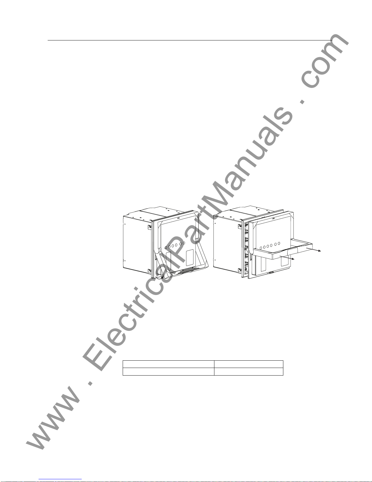
 'HWDFKLQJDQGLQVWDOOLQJWKHSOXJLQXQLW
Prior to detaching the plug-in unit from the case, the auxiliary voltage must be
disconnected.To detachtheplug-inunit,liftthelowerhandleuntilthe spring-loaded
locks on both sides of the handle are released and the unit is pushed about 6 mm out
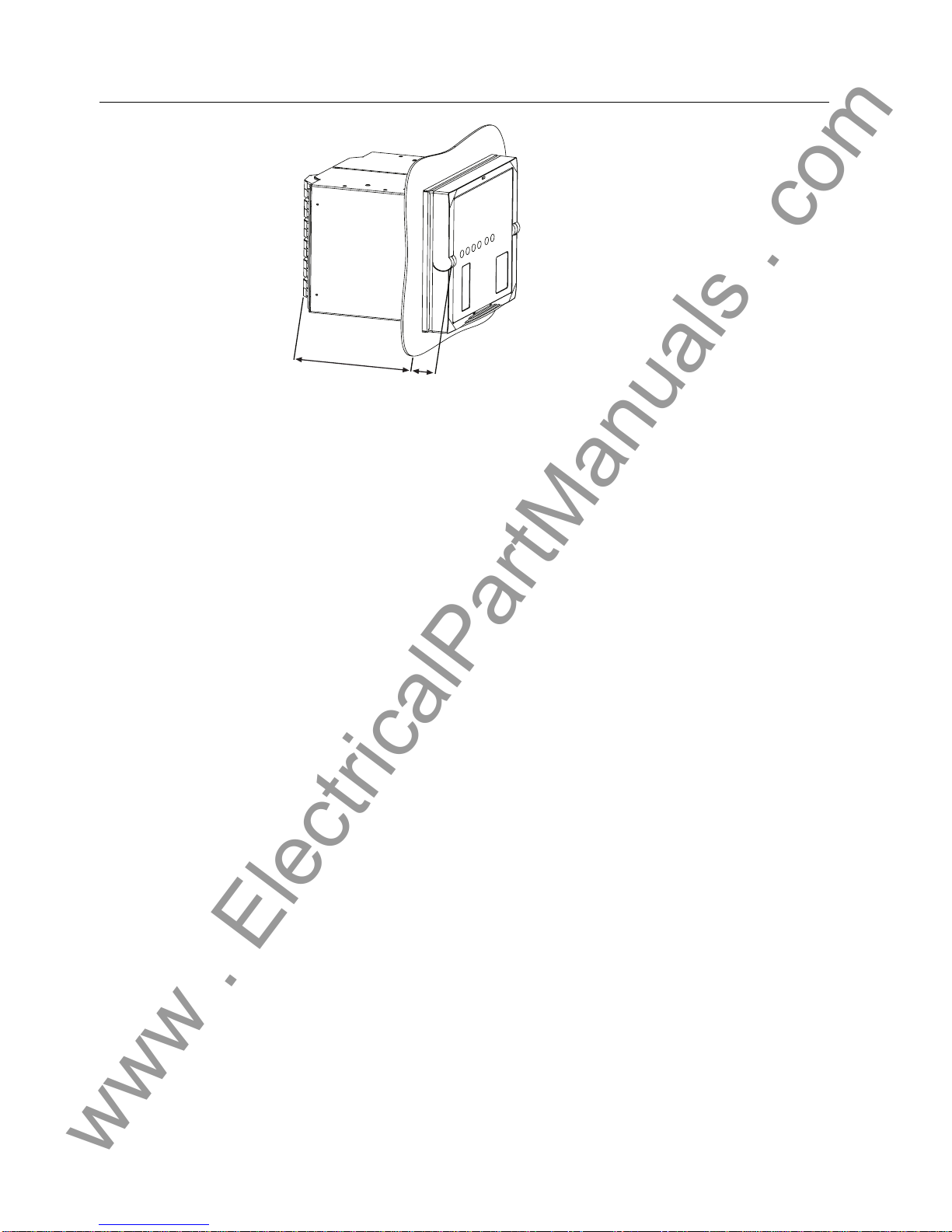
of the case. This will separate the connectors and you can easily pull the unit out of
the case.
The relay features an automatic short-circuit mechanism in the current transformer
(CT) connector. Therefore, detaching the plug-in unit will not open the secondary
circuit of the CT which otherwise could cause dangerously high voltages.
Signal connectors will be left open when the plug-in unit is detached.
)LJ 'HWDFKLQJWKHSOXJLQXQLWIURPWKHFDVH
1RWH
Before fitting a relay plug-in unit into a relay case, check that the unit and the case
have the same order number. The order number of the case is printed on the bottom
plate inside the case. However, if a substitute plug-in unit has to be used instead of
the original unit, ensure that at least the first ten characters in the order numbers of
the case and the plug-in unit are identical, as in the following example:
In order to obtain the identical functionality to that of the original product, all
charactersinthe ordernumber,exceptforthoseindicatinga sparepart,shouldmatch
the ones of the case.
Order number of the relay case 5(0$+CMP
Order number of the plug-in unit 5(0$+CNR
Detaching_a
www . ElectricalPartManuals . com
8
1MRS 752265-MUM
0RWRU3URWHFWLRQ5HOD\
Installation Manual
5(0
The relay features a built-in mechanical coding system that helps to prevent
dangerous situations from arising, should a non-suitable plug-in unit be fitted into a
relay case.
To install a plug-in unit into a case, first check that the lower handle is down in its
initial position and then push the unit into the case until the locks click; see the figure
below:
)LJ ,QVWDOOLQJWKHSOXJLQXQLWLQWRWKHFDVH
 0RXQWLQJGLPHQVLRQV
)LJ DLQGLPHQVLRQVRI5( 
Danger!
Forcing a non-suitable plug-in unit into a case will break the relay
and may cause dangerous situations.
!
Installing_a
)UDPHZLGWKPP )UDPHKHLJKWPP )UDPHGHSWKPP
177 177 149.3
177
177 (4U)
30.8
149.3
180.1
160
164
Dimen ion _a
www . ElectricalPartManuals . com
1MRS 752265-MUM 0RWRU3URWHFWLRQ5HOD\
Installation Manual
5(0
9
 )OXVKPRXQWLQJ
You will not need a separate mounting kit when flush mounting the case. All
mounting accessories are included in the case.
To flush mount the case to the cut-out in the panel, first loosen the 4 M5 fixing
screws approximately 7 turns. Mount the case to the mounting cut-out and tighten
the screws; see Fig. 4.3.-1. The allowed value range for the fixing screws’tightening
torque is 0.7...1Nm.
The enclosure class of the flush-mounted device is IP 54 on the front side, while the
rear side fulfils the IP 20 requirements (top of the relay: IP 40).
)LJ )OXVKPRXQWLQJRIDFDVH
Caution!
A device equipped with optic connections requires a minimum
depth of 180 mm.
!
Flu hPanel_a
Panel
161.5
+1.0
-1.0
165.5
+1.0
-1.0
Ca e
Fixing crew
M5 T25 Torx head
Flu hScrew_a
www . ElectricalPartManuals . com
10
1MRS 752265-MUM
0RWRU3URWHFWLRQ5HOD\
Installation Manual
5(0
)LJ 5HOD\FDVHDQGSOXJLQXQLWIOXVKPRXQWHG
Flu hMount_a
149,3
30,8
www . ElectricalPartManuals . com
1MRS 752265-MUM 0RWRU3URWHFWLRQ5HOD\
Installation Manual
5(0
11
 6HPLIOXVKPRXQWLQJ
The semi-flush mounting kit (1MRS050696) includes a raising frame, a gasket and
screws and is needed for the semi-flush mounting of a case. The gasket is used when
an IP 54 degree of protection (according to the IEC 60529) is required for the front
side. If the gasket is not used, an IP 50 degree of protection is obtained.
Mount the raising frame to the cut-out in the panel with four screws according to Fig.
4.4.-1.
)LJ 6HPLIOXVKPRXQWLQJ
Caution!
A device equipped with optic connections requires a minimum
depth of 130 mm
!
Rai Frame_a
Ø 5.5
165.5
+1
-1
173.5
+0.3
-0.3
161.5
+1
-1
133
+0.3
-0.3
Panel
Rai ing frame
M4 crew
Dimen ion of panel cut out
Ca eMount_a
Ca e
www . ElectricalPartManuals . com
12
1MRS 752265-MUM
0RWRU3URWHFWLRQ5HOD\
Installation Manual
5(0
For instructions on how to mount the case to the raising frame, refer to section Flush
mounting.
)LJ 5HOD\UDLVLQJIUDPHFDVHDQGSOXJLQXQLWVHPLIOXVKPRXQWHG
99,3
80,8
SemiMount_a
www . ElectricalPartManuals . com
1MRS 752265-MUM 0RWRU3URWHFWLRQ5HOD\
Installation Manual
5(0
13
 5DFNPRXQWLQJ
The case can be mounted in a 19" rack using one of two different mounting panels.
The type of mounting panel required depends on the number of cases mounted.
When mounting only one relay, use mounting kit number 1MRS050694. When
mounting two relays next to each other, use mounting kit number 1MRS050695.
)LJ ´UDFNPRXQWLQJSDQHOV
For instructions on how to mount the case to the panel, refer to section Flush
mounting.
)LJ 5HOD\FDVHDQGSOXJLQXQLWUDFNPRXQWHG
Caution!
A device equipped with optic connections requires a minimum
depth of 180 mm.
!
RackPanel _a
19 (482,6)
4U (177)
149.3
30.8
RackMount_a
www . ElectricalPartManuals . com
14
1MRS 752265-MUM
0RWRU3URWHFWLRQ5HOD\
Installation Manual
5(0
 :DOOPRXQWLQJ
Kit 1MRS050697 is used for mounting the case on a wall, i.e. projection mounting,
and contains two two-piece mounting brackets (frame and rail parts), a backplate
andscrews.The mountingbracketsare madeof prepainted(light-grey,Pantone420)
steel sheet. The kit also includes detailed mounting instructions and dimensions for
screw holes.
A wall-mounted case can be pulled out 160 mm and turned 45 (or 90) degrees
downwards(or upwards) when the wires are to beconnected. Part “A”locks the case
toselected(pushed-inorpulled-out)position,see figuresbelow.Thecase isreleased
by pushing the locks. By loosening the knurled-head screw “B”, the case can be
rotated, see Fig. 4.6.-2.
)LJ 5HOD\FDVHDQGSOXJLQXQLWZDOOPRXQWHG
)LJ :DOOPRXQWHGUHOD\LQSXOOHGRXWSRVLWLRQDQGURWDWHG
177
253
214
wallmount_a
177
253
214
wallmount_a
177
253
214
wallmount_a
177
253
214
wallmount_a
177
253
214
wallmount_a
A
450
rotated_a
413
A
B
50 mm pace needed
above and below
the frame for rotating
Min 50 mm pacing
between two kit
www . ElectricalPartManuals . com
1MRS 752265-MUM 0RWRU3URWHFWLRQ5HOD\
Installation Manual
5(0
15
 &RQQHFWLRQV
Connection terminals are described in the Technical Reference Manual. Each
contact has its own identification number, X2.1, for instance. The numbering of the
contacts runs from top to bottom, except the connectors X2.1 and X5.5 which are
numbered from bottom to top; see Fig. 5.1.-1.
Terminal blocks of screw-compression and ring-lug type are used for electrical
connections while transceivers of snap-in type are used for plastic fibre-optic
connections. If terminals of screw-compression type are used:
1. Open the screw terminal before inserting a wire into it for the first time. To open
the screw terminal, turn the fixing screw anticlockwise until the terminal hole is
wide open (the inside of the terminal hole is surrounded by metal).
2. Insert the wire and turn the fixing screw clockwise until the wire is firmly fixed.
Only use screwdriver and insert bits for Phillips (PH 1) cross-recessed head screws
(M3.5) when handling CT terminals (X2.1) of screw-compression type.
)LJ 6FUHZGULYHUDQGLQVHUWELWVIRU&7WHUPLQDOVRIVFUHZFRPSUHVVLRQW\SH
It is also possible to use terminals of ring-lug type for the CTs. If using terminals of
ring-lug type:
1. Open the lid that covers the ring-lug fixing screw (every fixing screw has its
own lid) with the tip of a screwdriver.
2. Screw off the screw, slide it through the terminal lug and screw it back on.
3. Close the lid.
When the wires for the CTs have been connected, install the snap ferrite ring,
provided with the relay, around the wires as close to the relay terminals as possible.
 (OHFWULFDOFRQQHFWLRQV
All connections are made on the rear of the case. No soldering is needed.
Each signal connector (X3.1 and X4.1) terminal is dimensioned for one 0.2...2.5
mm2 wire or two 0.2...1.0 mm2wires.
Connect the wires from the CTs to the right device according to the phase order and
the coupling scheme. Each terminal for CTs is dimensioned for one 0.5...6.0 mm2
wire or for two maximum 2.5 mm2wires.
A separate earth lead of at least 2.5 mm2has to be connected from the protective
earth screw between connectors X4.1 and X3.1 (upper screw; see Fig. 5.1.-1) to the
earth bar.
A) B) C)
MAX 5 mm
MIN 15 mm
D)
Screwdriver_a
MAX 5.5 mm
www . ElectricalPartManuals . com
16
1MRS 752265-MUM
0RWRU3URWHFWLRQ5HOD\
Installation Manual
5(0
When using RTD sensors or thermistors, use a double shielded cable. Connect the
cable shields to the chassis earth screw between connectors X4.1 and X3.1 (lower
screw; see Fig. 5.1.-1).
Terminals on the optional RS-485 communication module are dimensioned for one
0.08...1.5 mm2wire or for two maximum 0.75 mm2wires.
)LJ 5HDUYLHZRI5( ZLWKWKH56FRPPXQLFDWLRQPRGXOH
DANGER - RISK OF ELECTRIC SHOCK
NEAR INSTRUMENT TERMINALS
!
1
2
3
5
6
7
8
9
10
11
12
13
1
15
16
17
18
19
20
21
22
23
2
1
2
3
5
6
7
8
9
10
11
12
13
1
15
16
17
18
19
20
21
22
23
2
1 2 3 5 6 7 8 9 10 11 12
X3.1
X .1
X2.1
X5.5
6
5
3
2
1
RearRS_REM610_a
www . ElectricalPartManuals . com
1MRS 752265-MUM 0RWRU3URWHFWLRQ5HOD\
Installation Manual
5(0
17
)LJ 5HDUYLHZRI5( ZLWKWKHILEUHRSWLFFRPPXQLFDWLRQPRGXOHIRU
SODVWLFILEUH
1
2
3
5
6
7
8
9
10
11
12
13
1
15
16
17
18
19
20
21
22
23
2
1
2
3
5
6
7
8
9
10
11
12
13
1
15
16
17
18
19
20
21
22
23
2
1 2 3 5 6 7 8 9 10 11 12
X3.1
X .1
X5.3
TX
RX
X2.1
DANGER - RISK OF ELECTRIC SHOCK
NEAR INSTRUMENT TERMINALS
!
RearFiberREM610_a
www . ElectricalPartManuals . com
18
1MRS 752265-MUM
0RWRU3URWHFWLRQ5HOD\
Installation Manual
5(0
5HIHUHQFHV
Other available manuals:
•Technical Reference Manual, 1MRS 752263-MUM
•Operator’s Manual, 1MRS 752264-MUM
www . ElectricalPartManuals . com
$%%2\
Substation Automation
P.O. Box 699
FIN-65101 VAASA
Finland
Tel. +358 10 22 11
Fax. +358 10 224 1094
www.abb.com/substationautomation
1MRS 752265-MUM EN 11.2003
www . ElectricalPartManuals . com

Other manuals for REM 610

9

Other ABB Relay manuals

ABB CM-TCN User manual

ABB

ABB CM-TCN User manual

ABB CR324GXNS User manual

ABB

ABB CR324GXNS User manual

ABB CT-C Series User manual

ABB

ABB CT-C Series User manual

ABB CWC Manual

ABB

ABB CWC Manual

ABB CRN-1 Manual

ABB

ABB CRN-1 Manual

ABB RELION Series Installation and operation manual

ABB

ABB RELION Series Installation and operation manual

ABB HU Manual

ABB

ABB HU Manual

ABB SSR32 User manual

ABB

ABB SSR32 User manual

ABB A140-H56 User manual

ABB

ABB A140-H56 User manual

ABB CR324CXCS User manual

ABB

ABB CR324CXCS User manual

ABB CM-MSS Firmware update

ABB

ABB CM-MSS Firmware update

ABB CM-ESS.1 User manual

ABB

ABB CM-ESS.1 User manual

ABB CM Manual

ABB

ABB CM Manual

ABB Relion RER615 DNP3 User manual

ABB

ABB Relion RER615 DNP3 User manual

ABB REJ 525 User manual

ABB

ABB REJ 525 User manual

ABB PMA Manual

ABB

ABB PMA Manual

ABB IRP Manual

ABB

ABB IRP Manual

ABB Relion REC615 User manual

ABB

ABB Relion REC615 User manual

ABB REU 610 Product manual

ABB

ABB REU 610 Product manual

ABB SPAS 348 C Parts list manual

ABB

ABB SPAS 348 C Parts list manual

ABB BT50 User manual

ABB

ABB BT50 User manual

ABB Modures LZ91 User guide

ABB

ABB Modures LZ91 User guide

ABB AS400 User manual

ABB

ABB AS400 User manual

ABB CO User manual

ABB

ABB CO User manual

Popular Relay manuals by other brands

GE 750 instruction manual

GE

GE 750 instruction manual

Samwha DSP DSP-VIP-PL manual

Samwha DSP

Samwha DSP DSP-VIP-PL manual

Hella 3099 Operation and installation instructions

Hella

Hella 3099 Operation and installation instructions

Viessmann 5551 Operation manual

Viessmann

Viessmann 5551 Operation manual

Pilz 21693-6NL-07 operating instructions

Pilz

Pilz 21693-6NL-07 operating instructions

Pickering 60-890-003 user manual

Pickering

Pickering 60-890-003 user manual

MIEPL YTC YT-520 Series product manual

MIEPL

MIEPL YTC YT-520 Series product manual

Micom ALSTOM P341 Documentation

Micom

Micom ALSTOM P341 Documentation

Siemens 7SG12 DAD-N manual

Siemens

Siemens 7SG12 DAD-N manual

GE 350-A9 quick start guide

GE

GE 350-A9 quick start guide

Siemens SIRIUS 3RA2943-2AA1 Original operating instructions

Siemens

Siemens SIRIUS 3RA2943-2AA1 Original operating instructions

Schrack LSZ6W Series Assembly

Schrack

Schrack LSZ6W Series Assembly

GMI D5094S-104 instruction manual

GMI

GMI D5094S-104 instruction manual

Pilz PNOZ 16SP operating instructions

Pilz

Pilz PNOZ 16SP operating instructions

Beluk KSR-V Technical documentation

Beluk

Beluk KSR-V Technical documentation

Crouzet GNR Installation sheet

Crouzet

Crouzet GNR Installation sheet

Mastervolt Digital AC 1x6A user manual

Mastervolt

Mastervolt Digital AC 1x6A user manual

Viessmann 5228 Operation manual

Viessmann

Viessmann 5228 Operation manual

manuals.online logo
manuals.online logoBrands
  • About & Mission
  • Contact us
  • Privacy Policy
  • Terms and Conditions

Copyright 2025 Manuals.Online. All Rights Reserved.