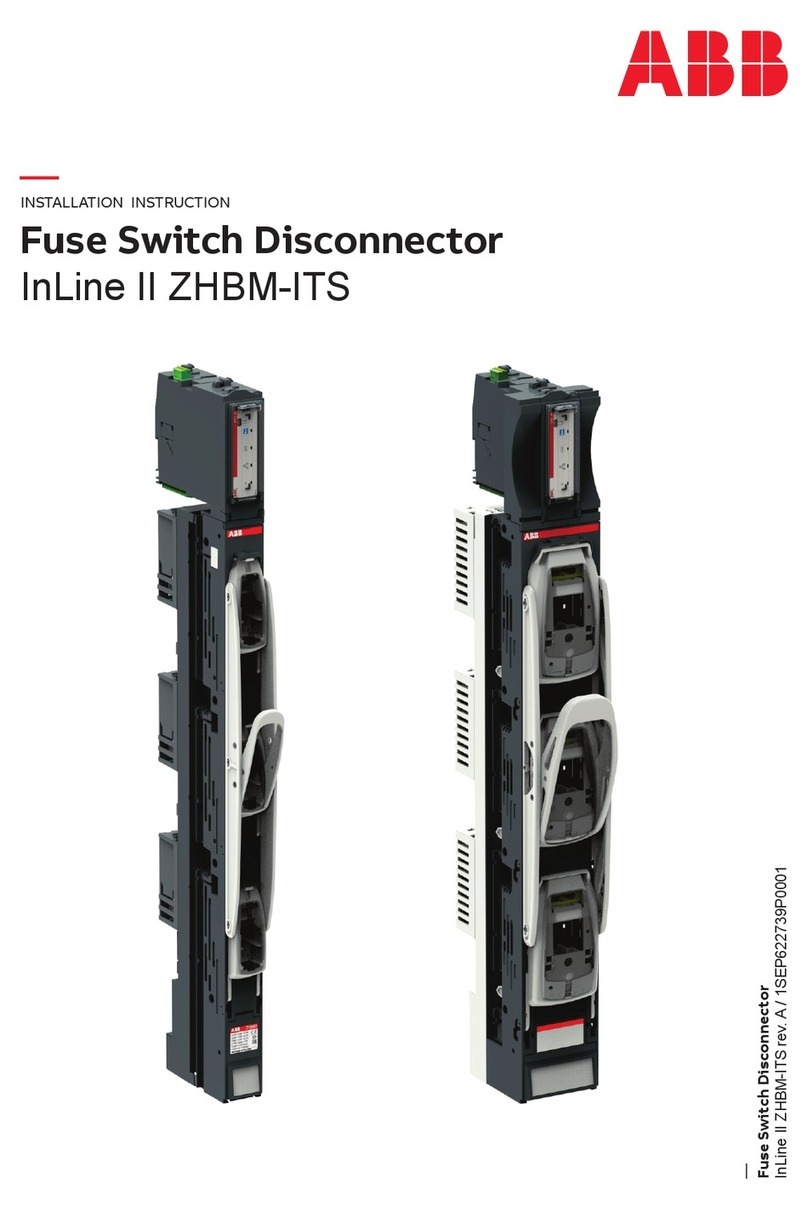
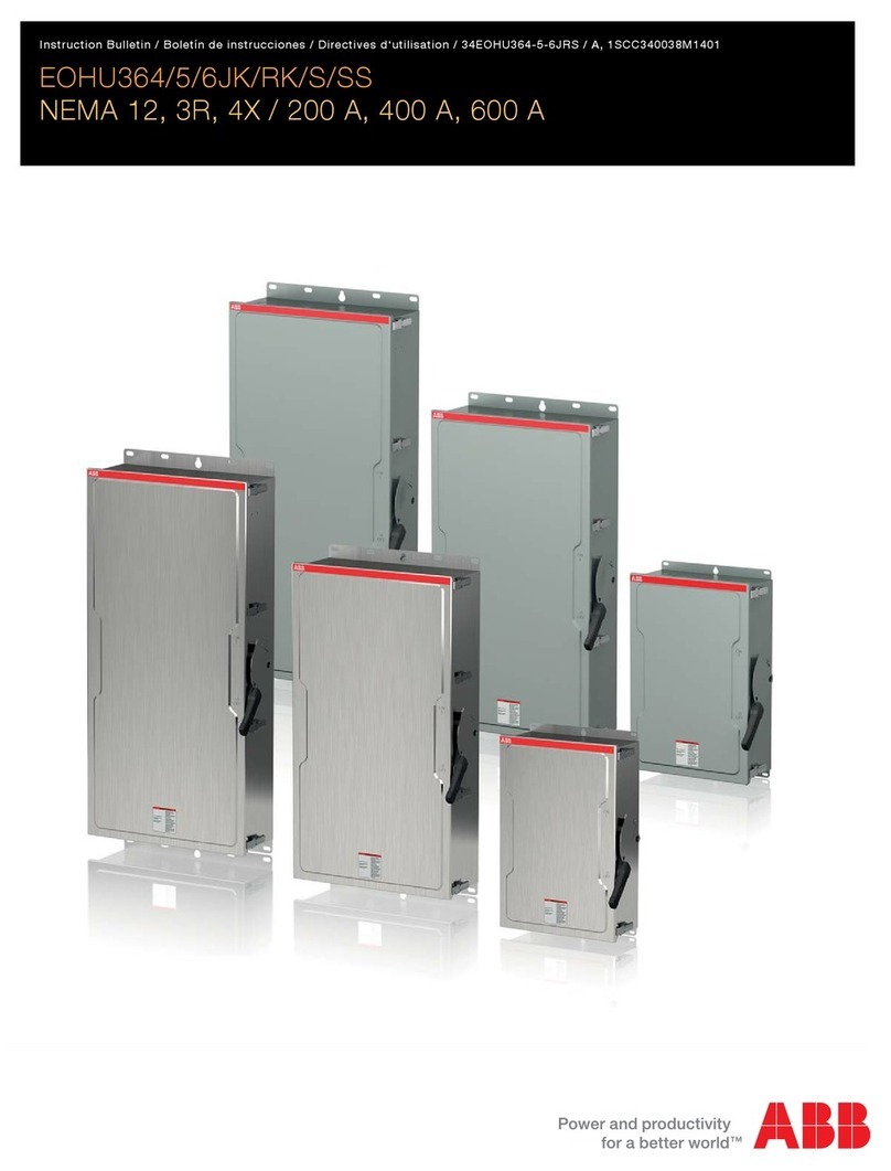
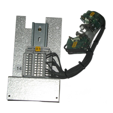
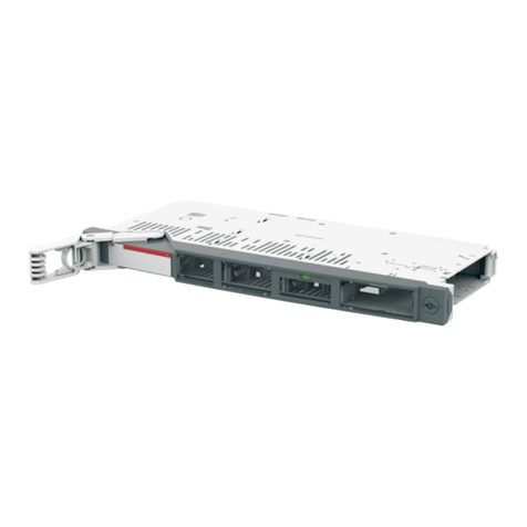
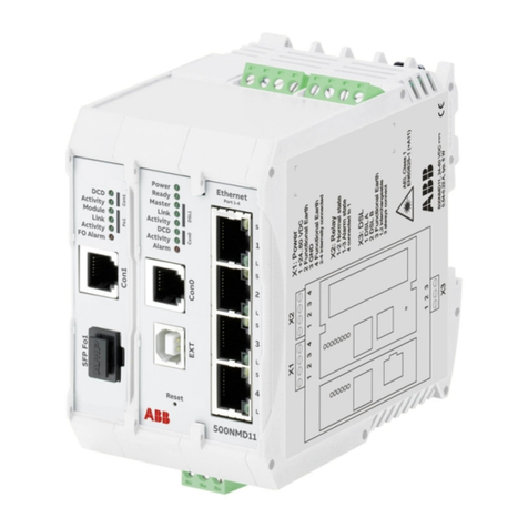
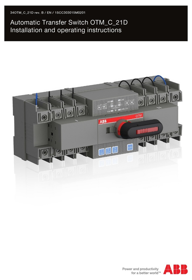
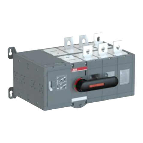
ABB TruONE ATS OXB250E3S3QT User manual

—
SERVICE INSTRUCTION; MECHANISM, FRAME, POWER AND CONTROL MODULES
TruONE® ATS Automatic transfer switches
Replacement of mechanism and spare parts
—
TruONE® ATS Automatic transfer switches
34OX_MECH_ rev. B / 1SCC303018M0201

2AUTOMATIC TRANSFER SWITCHES, REPLACEMENT OF SPARE PARTS
Additional information
We reserve the right to make technical
changes or modify the contents of this
document without prior notice. With
regard to purchase orders, the agreed
particulars shall prevail. ABB does not
accept any responsibility whatsoever for
potential errors or possible lack of infor-
mation in this document.
We reserve all rights in this document
and in the subject matter and illustra-
tions contained therein. Any reproduc-
tion, disclosure to third parties or
utilization of its contents – in whole or
in parts – is forbidden without prior
written consent of ABB.

3
34OX_MECH_ REV.B, 1SCC303018M0201
—
Read these safety instructions carefully
before starting work!
• Detailed descriptions of standard proce-
dures for installation, use, maintenance
and principles for safe operation are not
included. It is important to note that this
document contains safety and precaution
instructions, against certain methods (of
installation, use and maintenance) that
could cause harm to personnel, damage
devices, or make them unsafe.
• These warnings and alarms do not in-
clude all conceivable ways to make instal-
lation, use and maintenance recom-
mended by ABB or not, that may be made,
or possible consequences and complica-
tions of each conceivable way, nor shall
ABB investigate all those ways.
• Anyone using maintenance procedures or
devices, recommended by ABB or not,
must check thoroughly that neither per-
sonal safety nor the safety devices are
endangered by mode of installation, use,
maintenance or the instruments used.
For more information, questions or spe-
cific problems contact your nearest ABB
representative.
Warning
• This manual is written for qualified per-
sonnel only and is not intended as a sub-
stitute for a proper course, or experience
about safety procedures for this device.
• For the products equipped with commu-
nication, the purchaser, the installer or
the final customer is responsible for ap-
plying all the IT security measures neces-
sary in order to prevent risks deriving
from connection to communication net-
works; such risks include, among other
things, the use of the product by unau-
thorized persons, alteration of its normal
functionality, accessing and modifying
the information.
• The purchaser, installer or end user is re-
sponsible for ensuring that notices and
safety signs are posted and that all ac-
cess points and switching devices are
locked securely when the switchgear is
left unattended, even momentarily.
• All the information contained in this doc-
ument reflects the latest product infor-
mation available at the time of printing.
We reserve the right to edit the document
at any time and without notice.
4AUTOMATIC TRANSFER SWITCHES, REPLACEMENT OF SPARE PARTS
—
Risk of electric shock or accident!
Before proceeding with any maintenance
operation, it is mandatory to:
• Disconnect the power supply to the
power circuit and auxiliary circuits and
visibly ground the terminals on both the
supply side and load side.
• Use adequate personal protection equip-
ment, ensure that the apparatus is in a
safe condition and proceed in accordance
with the Laws in force.
The maintenance operations must be car-
ried out by skilled personnel:
• An electrical skilled personnel (IEV 195-
04-01: person with relevant education
and experience to enable him or her to
perceive risks and to avoid hazards which
electricity can create).
• ABB declines all liability for damage to
persons or property caused by failure to
comply with the instructions in this docu-
ment.
Hazard
—
Tools needed
Torx 20, long,
min. 140 mm

5
34OX_MECH_ REV.B, 1SCC303018M0201
—
Service instruction
Automatic transfer
switches, TruONE® ATS
1. Removing the complete mechanism
from the switch, OX_30...1600_ 6
2. Replacing of complete mechanism
with electronics, OX_30...1600_ 9
3. OX_30...400_ | Removing of frame,
control and power modules 14
REMARK! See also Chapter 1: Removing
complete mechanism from the switch
4. OX_30...400_ | Replacing of frame,
power and control modules 18
REMARK! See also Chapter 2: Replacing of
complete mechanism with electronics
5. OX_400U...1600 | Removing of frame,
control and power modules 23
REMARK! See also Chapter 1: Removing
complete mechanism from the switch
6. OX_400U...1600 | Replacing of frame,
power and control modules 27
REMARK! See also Chapter 2: Replacing of
complete mechanism with electronics
13 2456

6AUTOMATIC TRANSFER SWITCHES, REPLACEMENT OF SPARE PARTS
6
1
—
Removing the complete mechanism
from the switch, OX_30...1600_
!

7
34OX_MECH_ REV.B, 1SCC303018M0201 7
1

8AUTOMATIC TRANSFER SWITCHES, REPLACEMENT OF SPARE PARTS
8
1
A
Short-circuit current ratings: Short-time current ratings:
J
ABB / Tmax T5L, T5V
OXA400X3X3QBM
480VAC 400A
MADE IN FINLAND
TRANSFER SWITCH
IEC 60947-6-1
Icm
30kA /100ms
Icw
36kA
415V 400A AC-31B
415V 400A AC-33B
Uimp 6 kV
Ie400A 50...60Hz
Class PC
Minimum enclosure:
height mm
width mm
depth mm
Use Cu-Al conductors
60˚C Wire only
Suitable for use
with terminal kit
OZXA400 or
OZXA400L
4x2-600 MCM
Terminaltorque 500 lb-in
1180
560
217
400A
RMS
SYMM AMPS
X1000
VOLTAGE
MAX
FUSE CLASS or
CIRCUIT BREAKER
MANUFACTURER/ TYPE
AMPS
MAX
RMS
SYMM AMPS
X1000
VOLTAGE
MAX
TIME DURATION
Sec. 30
RMS
SYMM AMPS
X1000
VOLTAGE
MAX
TIME DURATION
Sec.
gG
480
Automatic Transfer Switch
for use Emergency or
Standby Systems
50
40
480
480
0.03
0.06
0.1
0.3
0.5
600
400
800
480
480
415
100
50
100

9
34OX_MECH_ REV.B, 1SCC303018M0201 99
2
!
—
Replacing of complete mechanism with
electronics, OX_30...1600_ / OX_MECH_
Complete mechanism with
electronics (without HMI)
• Open transition (I - II)
- Level 2: OXAMECH-2-L2,
OXAMECH-3-L2, OXAMECH-4-L2
- Level 3: OXAMECH-2-L3,
OXAMECH-3-L3, OXAMECH-4-L3
- Level 4: OXAMECH-2-L4,
OXAMECH-3-L4, OXAMECH-4-L4
• Delayed transition (I - O - II or II - O - I)
- Level 2: OXBMECH-2-L2,
OXBMECH-3-L2, OXBMECH-4-L2
- Level 3: OXBMECH-2-L3,
OXBMECH-3-L3, OXBMECH-4-L3
- Level 4: OXBMECH-2-L4,
OXBMECH-3-L4, OXBMECH-4-L4
Check the handle position in the new
mechanism is same as the indication in
the switch! Use the handle if needed!
A

10 AUTOMATIC TRANSFER SWITCHES, REPLACEMENT OF SPARE PARTS
10
2
1 Nm / 8.75 lb.in

11
34OX_MECH_ REV.B, 1SCC303018M0201 1111
2
Configuration with Ekip
Programming -module by
using Ekip Connect
-software.

12 AUTOMATIC TRANSFER SWITCHES, REPLACEMENT OF SPARE PARTS
12
2
Click

13
34OX_MECH_ REV.B, 1SCC303018M0201 1313
2
!
AUTO

14 AUTOMATIC TRANSFER SWITCHES, REPLACEMENT OF SPARE PARTS
14
3
See Chapter 1 to remove the
mechanism from the switch.
—
OX_30...400_ | Removing of frame,
control and power modules
3
2
1

15
34OX_MECH_ REV.B, 1SCC303018M0201 15
3
Removing of control module
Short-circuit current ratings: Short-time current ratings:
J
ABB / Tmax T5L, T5V
OXA400X3X3QBM
480VAC 400A
MADE IN FINLAND
TRANSFER SWITCH
IEC 60947-6-1
Icm
30kA /100ms
Icw
36kA
415V 400A AC-31B
415V 400A AC-33B
Uimp 6 kV
Ie400A 50...60Hz
Class PC
Minimum enclosure:
height mm
width mm
depth mm
Use Cu-Al conductors
60˚C Wire only
Suitable for use
with terminal kit
OZXA400 or
OZXA400L
4x2-600 MCM
Terminaltorque 500 lb-in
1180
560
217
400A
RMS
SYMM AMPS
X1000
VOLTAGE
MAX
FUSE CLASS or
CIRCUIT BREAKER
MANUFACTURER/ TYPE
AMPS
MAX
RMS
SYMM AMPS
X1000
VOLTAGE
MAX
TIME DURATION
Sec. 30
RMS
SYMM AMPS
X1000
VOLTAGE
MAX
TIME DURATION
Sec.
gG
480
Automatic Transfer Switch
for use Emergency or
Standby Systems
50
40
480
480
0.03
0.06
0.1
0.3
0.5
600
400
800
480
480
415
100
50
100
!
OX_CONTROL-400-L_
Torx 20
HAZARDOUS
VOLTAGE
Willcause death, burn or
seriousinjury.
WARNING
-more than one
livecircuit-disconnect all
sourcesof supply before
servicing.
TENSION
PELIGROSA
Causamuerte, incendio
oaccidentes graves.
ADVERTENCIA
-Más de un circuito vivo-
Desconectetodas las fuentes de
suministroantes de servicio.
Dangerde mort brûlures
oude blessures graves.
AVERTISSEMENT
-Plus d´un circuit sous tension-
débranchertoutes les
sourcesd´alimentation
avantd´entreprendre le
dépannage.
HAUTE
TENSION
WARNING
-Verify the condition of power source prior
tomanually tranferring.
Manualoperation may result in out-of-phase
transferwhen both sources are energized.
Forperiodic testing and adjusting transfer
voltage,transfer frequence and transfer
delaytime, see the instructional manual.
SHORT-CIRCUITWITHSTAND/CLOSING
ANDSHORT-TIMECURRENT RATINGS
WHENUSING SPECIFIC CIRCUIT
BREAKERSOR PROTECTED BY FUSES
Whenprotected by a specific circuit breaker
orby a fuse of the specific fuse class as
markedbelow, this transfer switch is
suitablefor use in circuits capable of
deliveringthe short-circuit current at the
maximumvoltage marked.
Whenthe circuit breaker has a short-time
response,it shall be coordinated with the
short-timecurrent rating of the transfer
switchshown below.
Cuandoesté protegida con un
fusiblede la clase específica y
corrientenominal máxima como se
muestraa continuación, esta
transferenciaes adecuada para
utilizarseen un circuito capaz de
liberarla corriente de contocircuito
ala tensión máxima marcada.
Convientà la commutation de la charge totale ďun
circuitsi la charge de tungsten ne dépasse pas de
30pourcent le couranr nominal du commutateur.
Lecourant de charge continu ne doit pas dépasser
de100 pourcent le courant nominal du commutateur.
AVERTISSEMENT
-Vérifier l´état de la source
d´alimentationavant un transfert manuel.
Uneopération manuelle peut entraîner un transfert
déphasési les deux sources sont sous tension.
COURANTSNOMINAUX DE RÉSISTANCE AU
COURT-CIRCUITETDE FERMETURE DE CIRCUIT
ETCOURANTS NOMINAUX DE COURTE DURÉE
POURDES DISJONCTEURS SPÉCIFIQUES.
Decommutateur, s´il est protégé par un disjoncteur
dontle nom du fabricant, le type et le courant
nominalsont indiqués plus bas, convient à des
circuitscapables dacheminer un courant de court-
circuità la tension maximale indiquée plus bas.
Sile disjoncteur est à déclenchement rapide, le
déclenchementdoit êntre coordonné au de
courtedurée du commutateur indigué plus bas.
COURANTSNOMINAUX DE RÉSISTANCE AU
COURT-CIRCUITETDE FERMETURE DE CIRCUIT
SILA PROTECTION EST ASSURÉE PAR DES
FUSIBLES.
Cecommutateur, sil est protégé par un fusible dont
laclasse et le courant nominal sont indiqués plus
bas,convient à un circuit capable dacheminer le
courantde court-circuit à la tension maximale
indiquée.
Adecuadopara transferencia completa
cuandola carga de tungsteno no exceda
30por ciento del valor nominal del equipo.
Lacorriente continua de la carga no
debeexceder 100 por ciento del valor
nominaldel equipo.
AGUANTEDE CORTOCIRCUITO/CORRIENTES
NOMINALESDE CIERRE Y CORTADURACIÓN
CUANDOSE UTILIZAN INTERRUPTORES
AUTOMÁTICOSESPECÍFICOS.
Cuandoesté protegida con un
interruptorautomático de un
fabricanteen específico, del tipo y
corrientenominal como se muestra
acontinuación, esta transferencia
esadecuada para utilizarse en un
circuitocapaz de liberar la corriente
decortocircuito a la tensioón
máximamarcada.
SIel interruptor automático tiene
unarespuesta de corta duración,
debecoordinarse con la corriente
nominalde corta duración de la
transferenciamostrada a
continuación.
AGUANTEDE CORTOCIRCUITO/VALOR
NOMINALDE CIERRE CUANDO SE
PROTEGECON FUSIBLES.
Suitablefor total system transfer where the
tungstenload does not exceed 30 percent of
theswitch rating.
Continuousload current not to exceed 100
percentof switch rating.
DANGER/
PELIGRO
!

16 AUTOMATIC TRANSFER SWITCHES, REPLACEMENT OF SPARE PARTS
16
3
Removing of power module
Hazard
Wait at least 60 seconds after
removing the mechanism before
disconnecting the connector to
allow the capacitors to
discharge.
Torx 20

17
34OX_MECH_ REV.B, 1SCC303018M0201 17
3

18 AUTOMATIC TRANSFER SWITCHES, REPLACEMENT OF SPARE PARTS
18
4
—
OX_30...400 | Replacing of frame, power
and control modules
Frame module
• Open transition (I - II)
- OXAFRAME-2
• Delayed transition (I - O - II or II - O - I)
- OXBFRAME-2
Power module
• Open transition (I - II) and delayed
transition (I - O - I or II - O - I)
- OXPOWER-400

19
34OX_MECH_ REV.B, 1SCC303018M0201 19
4
Torx 20,
1 Nm / 8.75 lb.in

20 AUTOMATIC TRANSFER SWITCHES, REPLACEMENT OF SPARE PARTS
20
4
Control module
• Open transition (I - II)
- Level 2: OXACONTROL-400-L2
- Level 3: OXACONTROL-400-L3
- Level 4: OXACONTROL-400-L4
• Delayed transition (I - O - II or II - O - I)
- Level 2: OXBCONTROL-400-L2
- Level 3: OXBCONTROL-400-L3
- Level 4: OXBCONTROL-400-L4
Apply warning label on top
of the closed connector.
This manual suits for next models
4
Table of contents
Other ABB Switch manuals
Popular Switch manuals by other brands

Sun Microsystems
Sun Microsystems StorageTek SL8500 4199516XX installation guide

Water Witch
Water Witch 217 installation instructions

Allied Telesis
Allied Telesis AT-8000S/24POE datasheet

Kramer
Kramer VW-4 user manual

Ruijie
Ruijie XS-S1920 Series Hardware installation and reference guide

NTI
NTI SERIMUX-CS-x Installation and operation manual