ABB Slimline XRG00 User manual
Other ABB Switch manuals

ABB
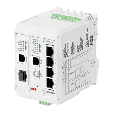
ABB NE820 User manual

ABB
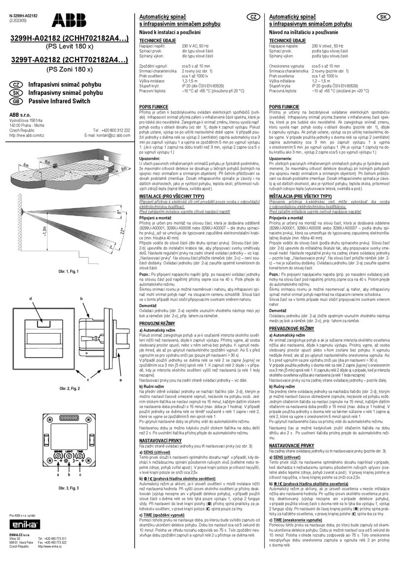
ABB 3299A-A12100 Operation manual
ABB
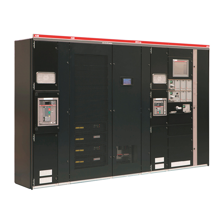
ABB MNS-Up User manual
ABB
ABB EDS500 Series Parts list manual
ABB
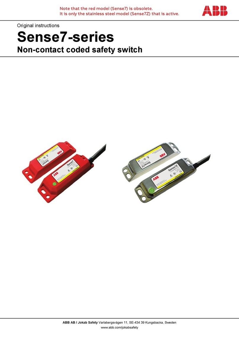
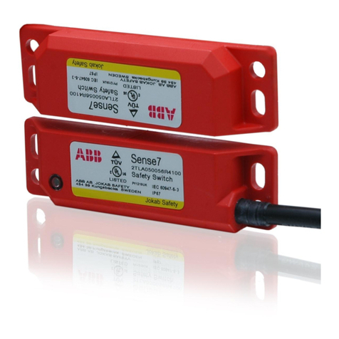
ABB Sense7 Series User manual
ABB
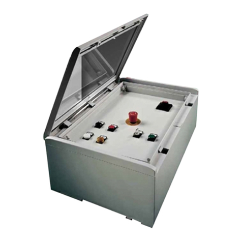
ABB 1SLC805002F0001 User manual
ABB
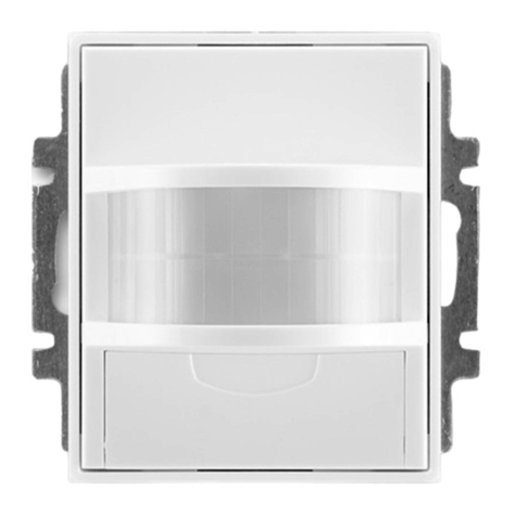
ABB 3299E-A32100 User manual
ABB
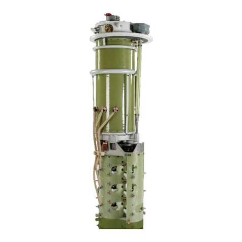
ABB UC Series Operating manual
ABB
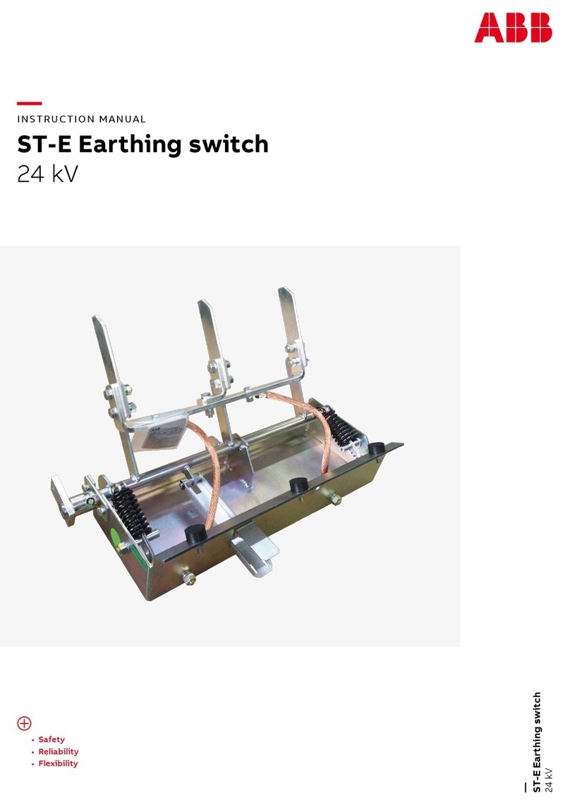
ABB ST-E Series User manual

ABB
ABB 3299-22958 User manual

ABB
ABB OWIII User manual
ABB
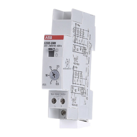
ABB E 232 E-230N User manual

ABB
ABB Uniswitch User manual
ABB
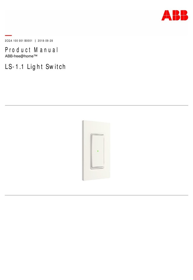
ABB ABB-free@home LS-1.1 User manual

ABB
ABB FIP2002 User manual
ABB
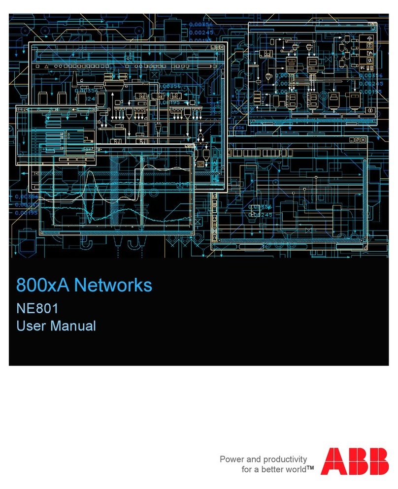
ABB NE801 User manual
ABB
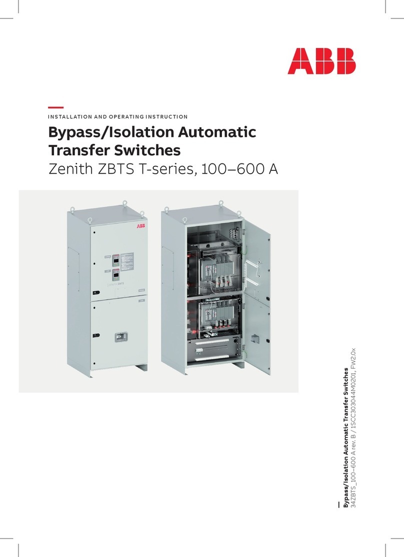
ABB Zenith ZBTS T Series User guide
ABB
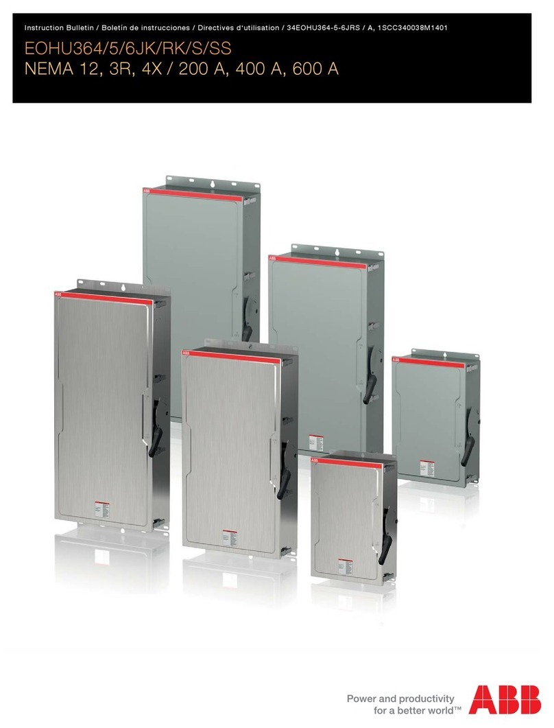
ABB EOHU Series Training manual
ABB
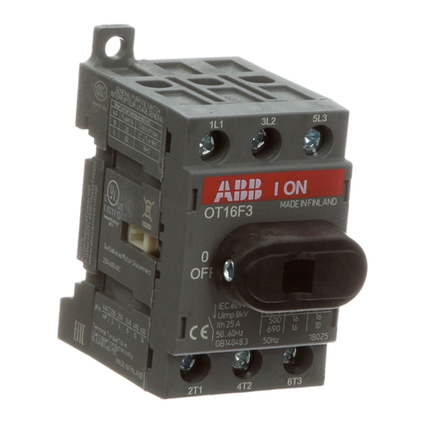
ABB OT16F3 User manual

ABB
ABB UniGear Series User manual

