2
1
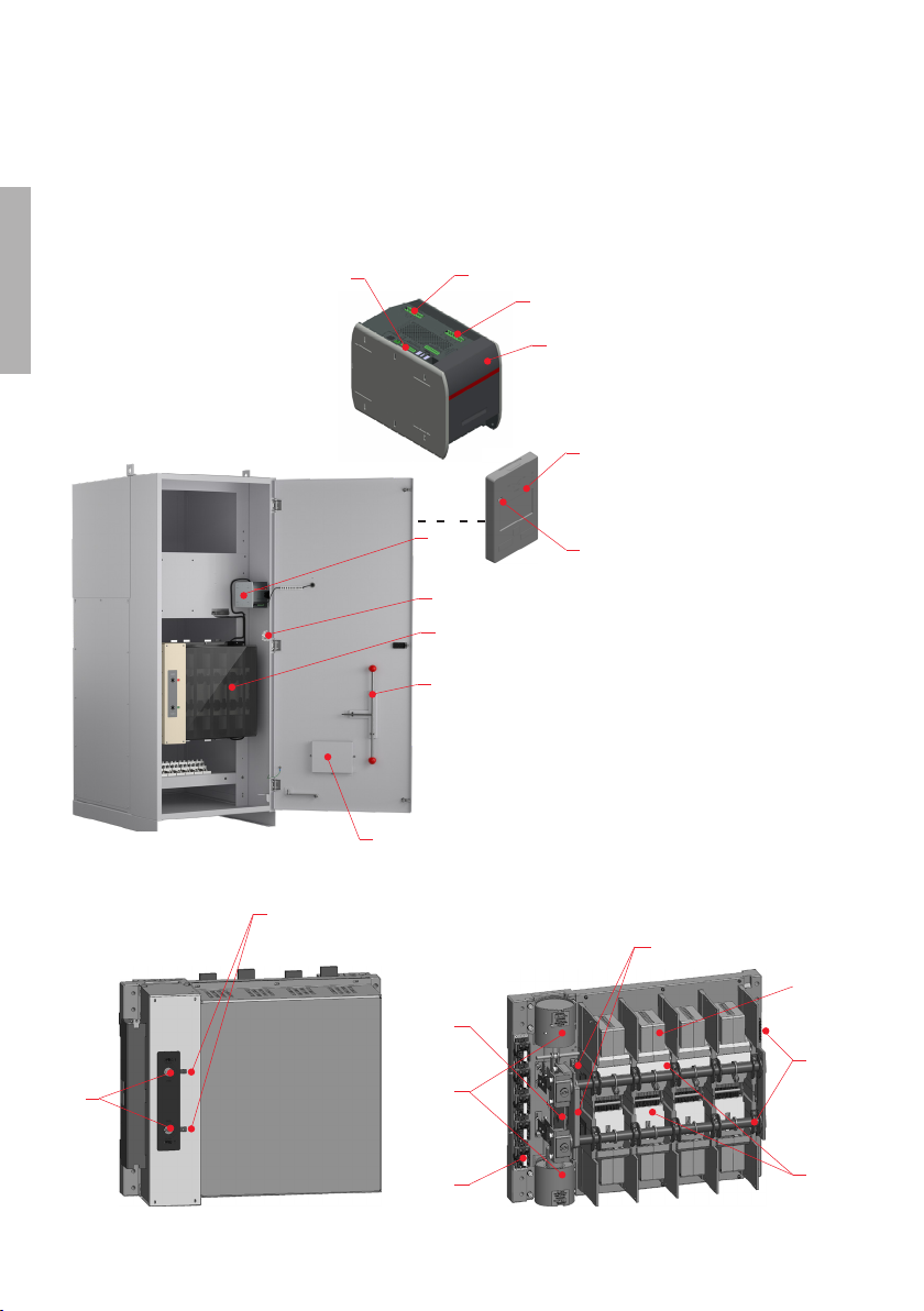
ZENITH ZTG(D/CT) T-SERIES 1600-3000 A
HAZARD OF ELECTRIC SHOCK,
EXPLOSION, OR ARC FLASH
• Apply appropriate personal protective
equipment and follow safe electrical
work practices.
• This equipment must only be installed
and serviced by qualified electrical per-
sonnel.
• Before performing visual inspections,
tests, or maintenance on the equip-
ment, disconnect all sources of electric
power. Assume that all circuits are live
unless they are completely de-ener-
gized, tested, grounded, and tagged.
Pay particular attention to the design of
the power system. Consider all sources
of power, including the possibility of
backfeeding.
• Disconnect all sources of electric power
before removing or making source side
or load side connections to the transfer
switch.
• Always use a properly rated voltage
sensing device at all line and load con-
nections to confirm transfer switch is
disconnected from all live electrical
sources.
• Turn off power supplying transfer
switch before doing any other work on
or inside switch.
Failure to follow these instructions could
result in death or serious injury.
Receiving and handling
Upon receipt, carefully inspect the trans-
fer switch for damage that may have oc-
curred during transit. If damage is evi-
dent, or there is visible indication of
rough handling, immediately file a dam-
age claim with the transportation com-
pany, and notify your local ABB sales
office.
Do not remove the shipping packaging
until ready to install the switch.
Storage
If the unit will not be placed into service
immediately, store the transfer switch in
its original package in a clean, dry loca-
tion. To prevent condensation, maintain a
uniform temperature. Store the unit in a
heated building, allowing adequate air
circulation and protection from dirt and
moisture. Storing the unit outdoors could
cause harmful condensation inside the
transfer switch enclosure.
HAZARD OF EQUIPMENT
OVERTURNING
When moving with a fork lift, do not
remove the shipping packaging until the
device is in its final location.
Failure to follow this instruction may
result in personal injury or equipment
damage.
—
Receiving, handling and storag
Read these safety instructions
carefully before using this produce
Warning
Indicates a hazardous situation that, if not
avoided, could result in death or serious
injury.
Danger
Indicates a hazardous situation that,
if not avoided, will result in death or
serious injury.