ABB 2600T EN Series User manual

- 1 -
2600T EN Series
Safety Pressure Transmitters
Models 266H/N
Models 268H/N
Operating instructions

- 2 -
The Company
ABB Automation is an established world force in the design and manufacture
of instrumentation for industrial process control, flow measurement, gas and
liquid analysis and environmental applications.
As a part of ABB, a world leader in process automation technology, we offer
customers application expertise, service and support worldwide.
We are committed to teamwork, high quality manufacturing, advanced
technology and unrivalled service and support.
The quality, accuracy and performance of the Company’s products result from
over 100 years experience, combined with a continuous program of innovative
design and development to incorporate the latest technology.
The NAMAS Calibration Laboratory No. 0255(B) is just one of the ten flow
calibration plants operated by the Company, and is indicative of ABB
Automation’s dedication to quality and accuracy.
UseofInstructions
Warning.
An instruction that draws attention to the risk of injury or
death.
Caution.
An instruction that draws attention to the risk of damage
to the product, process or surroundings.
R
E
G
I
S
T
E
R
E
D
F
I
R
M
BS EN ISO 9001
St Neots, U.K. – Cert. No. Q5907
Stonehouse, U.K. – Cert. No. FM 21106
Stonehouse, U.K. – Cert. No. 0255
UNI EN ISO 9001
Lenno, Italy – Cert. No. 9/90A
Although Warning hazards are related to personal injury, and Caution hazards are associated with equipment or property
damage, it must be understood that operation of damaged equipment could, under certain operational conditions, result in
degraded process system performance leading to personal injury or death. Therefore, comply fully with all Warning and
Caution notices.
Informationinthismanualisintendedonlytoassistourcustomersintheefficientoperationofourequipment.Useofthismanual
for any other purpose is specifically prohibited and its contents are not to be reproduced in full or part without prior approval
of Technical Communications Department, ABB Automation.
✶
Note.
Clarification of an instruction or additional information.
Information.
Further reference for more detailed information or
technical details.
ABB AUTOMATION
Health and Safety
To ensure that our products are safe and without risk to health, the following points must be noted:
1. The relevant sections of these instructions must be read carefully before proceeding.
2. Warning labels on containers and packages must be observed.
3. Installation, operation, maintenance and servicing must only be carried out by suitably trained personnel and in accordance with the
information given. Any deviation from these instructions, will transfer the complete liability to the user.
4. Normal safety precautions must be taken to avoid the possibility of an accident occurring when operating in conditions of high
pressure and/or temperature.
5. Chemicals must be stored away from heat, protected from temperature extremes and powders kept dry. Normal safe handling
procedures must be used.
6. When disposing of chemicals ensure that no two chemicals are mixed.
Safetyadviceconcerningtheuseofthe equipment described in thismanualoranyrelevanthazarddatasheets(where applicable) may
be obtained from the Company address on the back cover, together with servicing and spares information.

- 3 -
Section Page
INTRODUCTION............................................................3
TRANSPORT, STORAGE, HANDLING AND
PRODUCT IDENTIFICATION........................................4
SAFETY PHILOSOPHY, MANAGEMENT OF
FUNCTIONAL SAFETY, INFORMATION
REQUIREMENTS ..........................................................5
LIFE-CYCLE ACTIVITIES..............................................6
FAULT OUTSIDE THE FUNCTIONAL SAFETY............8
PRINCIPLE OF OPERATION ........................................9
INSTALLATION............................................................12
ELECTRICAL CONNECTIONS ...................................15
ELECTRICAL REQUIREMENTS ................................17
COMMISSIONING AND CONFIGURATION
ISSUES ........................................................................18
CALIBRATION .............................................................19
PRE-STARTUP ACCEPTANCE TEST,
PROOF TESTS............................................................21
DISMANTLING AND REASSEMBLY ..........................22
SIMPLE FAULT FINDING............................................23
RETURNING FORM ....................................................24
ADDENDUM FOR "METERS" OPTION OF
THE TRANSMITTERS .................................................25
ADDENDUM FOR COMETER OR INDICATOR
WITH HART PROGRAMMING CAPABILITY AND
PROMETER - PROGRAMMABLE INDICATOR ..........26
ADDENDUM FOR PV-SCALING OPERATION...........31
ADDENDUM FOR "SURGE PROTECTION" OPTION
OF THE TRANSMITTERS ...........................................32
ADDENDUM FOR SELECTABLE OUTPUT
FUNCTIONS ................................................................35
ADDENDUM FOR OUTPUT % RERANGING .............38
ADDENDUM FOR "EX SAFETY" ASPECTS
AND "IP" PROTECTION (EUROPE) ...........................39
CONTENTS INTRODUCTION
The 2600T series is a modular range of field mounted, micro-
processor based electronic transmitters, using a unique
inductive sensing element. The Model 266/268H/N is a
pressuretransmitterwith"singleport"processconnection;this
provides accurate and reliable measurement of gauge and
absolute pressure, in the even most difficult and hazardous
industrial environments.
Now a Safety pressure Transmitter is included in the 2600T
Series, with its analog output signal plus HART digital
communication.
The HART digital protocol allows remote re-ranging,
calibration and diagnostics, without any interference with the
standard 4-20 mA analog output signal.
This operating instructions manual describes the Safety
version of the 2600T Series transmitters and specify all
information necessary to safely connect the Safety 2600T
pressure transmitter in a Safety Instrumented System.
Itdetailsalsohowthesignalsfromtheinputfielddeviceshould
be interpreted.
Refer to the shortened contents of this manual, here in this
pageforaddressingthesectionofyourinterest,andalsotothe
supplementary documentation for additional remarks.
SUPPLEMENTARY DOCUMENTATION
Reference information on remote seals and configuration of
the transmitter can be found in the following documents:
SS/S26 Remote Seal Specification
2600T Data Sheets
IM / 691HT Hand-Held Communicator
Online HELP SMARTVISION Configuration Program
IEC61508Functional Safetyof e/e/peSafety-relatedsystems
ISAS84.01ApplicationofSafetyInstrumentedSystemsforthe
Process Industries
NE43 Standardization of the signal level for the breakdown
information of digital transmitters
Other helpful or general information can be found in the ABB
web site, at www.abb.com

- 4 -
Important - The instrument serial number must always be quoted when making enquiries.
PRODUCT IDENTIFICATION
The instrument is identified by the data plates shown in
Figure 1.
The Nameplate (Ref.A) provides information concerning the
code number, maximum working pressure, range and span
limits,powersupply andoutputsignal.See code/specification
sheet for detailed information. This plate also shows the
transmitterserialnumber. Pleaserefertothisnumberwhen
making enquiries.
Adedicatedlabel(Ref.B) isweldedasstandardtotheprimary
unit, carrying specific details of the transducer (diaphragms
material, fill fluid, range limits and identification number).
A Safety Marking plate ( Ref. C) is fitted when the transmitter
is required to comply with hazardous area regulations, e.g.
flameprooforintrinsicsafety protection.AdditionallyTagplate
(ref. D) provides the customer tag number and calibrated
range,maximumprocessworkingpressure(PS)andtempera-
ture (TS).
The instrument may be used as a safety accessory (category
IV)as definedby thePressure EquipmentDirective97/23/EC.
In this case, near the CE mark, there is the number of the
notified body (1130) that verified the compliance.
Fig. 1 - Product identification
TRANSPORT
After final calibration, the instrument is packed in a carton
(Type 2 to ANSI/ASME N45.2.2-1978), intended to provide
protection from physical damage.
STORAGE
The instrument does not require any special treatment if
stored as despatched and within the specified ambient
conditions level (Type 2 to ANSI/ASME N45.2.2-1978).
There is no limit to the storage period, although the terms of
guarantee remain as agreed with the Company and as given
in the order acknowledgement.
HANDLING
The instrument does not require any special precautions
during handling although normal good practice should be
observed.
Ref. B
Primary Unit
Ref. C
Ref. D
SERIAL
NUMBER
URL
DIAPHRAGM
MATERIAL
FILL
FLUID
Nameplate
Ref. A
3rd and 4th numerals show
the year of construction
(Ex) - - X X - - - -

- 5 -
SAFETY PHILOSOPHY
The Safety 2600T Pressure Transmitters are field devices
designedaccordingtherequirementsofthestandardIEC61508
fortheSafetyRelatedSystems.Standardcurrentlyusedfocus
on individual parts of all the safe instrumentation used to
implement a safety function. The IEC61508 defines
requirementsrelatedtoallthesystemthatnormallycomprises
initiating devices, logic solver and final elements. It also
introducestheconceptofSafetylifecycledefiningthesequence
of activities involved in the implementation of the safety
instrumented system from conception through
decommissioning. For a single component it is not correct to
define a SIL level. The term SIL (Safety Integrity Level) refers
tothecompletesafetyloopthereforethesingledeviceshall be
designedinordertobesuitabletoachievethedesiredSILlevel
in the entire Safety Loop.
Application
The Safety 2600T Pressure Transmitters are intended to be
applied for safety relevant application in the process industry.
They are suitable to be used in SIL2 applications. Special
attention has to be given to the separation of safety and non-
safety relevant use.
Physical Environment
The transmitter is designed for use in industrial field
environments and must be operated within the specified
environmental limits as indicated in the Transmitter Data
Sheet.
Role an Responsibilities
All the people, departments and organisations involved in the
life-cycle phases which are responsible for carrying out and
reviewingtheapplicableoverall,E/E/PES(Electrical/Electronic/
ProgrammableElectronicSystem) orsoftwaresafetylifecycle
phasesofaSafetyInstrumentedSystemshallbeidentified.All
those specified as responsible for management of functional
safetyactivitiesshallbeinformedoftheresponsibilitiesassigned
to them. All persons involved in any overall, E/E/PES or
software safety lifecycle activity, including management
activities, should have the appropriate training, technical
knowledge,experienceandqualificationsrelevanttothespecific
duties they have to perform.
MANAGEMENT OF FUNCTIONAL
SAFETY
For each application the installer of the owner of a safety
systemmustprepareaSafetyPlanningwhichmustbeupdated
throughout the Safety Life-cycle of the Safety Instrumented
System. The requirements for the management of functional
safety shall run in parallel with the overall safety lifecycle
phases.
Safety Planning
The Safety Planning shall consider:
• policies and strategies for achieving safety;
• safety life-cycle activities to be applied, including names of
responsible persons and departments;
• procedures relevant to the various life-cycle phases;
• audits and procedures for follow up.
INFORMATION REQUIREMENTS
The information shall comprehensively describe the system
installation and its use in order that all phases of the overall
safety lifecycles, the management of functional safety,
verification and the functional safety assessment can be
effectively performed.
Overall Safety Life-cycle Information
The overall safety lifecycle shall be used as the basis for
claimingconformancetothestandardIEC61508.Thelifecycle
phases consider all the activities related to the Safety
Instrumented System (SIS) from the initial concept through
design, implementation, operation and maintenance to
decommissioning.
The relevant lifecycle phases for the 2600T Safety Pressure
Transmitter used in a SIS are listed below:
Overall scope definition;
Hazard and risk analysis;
Overall safety requirements;
Safety requirement allocation;
Overall Operation and Maintenance planning;
Overall Installation and Commissioning planning;
Overall Installation and Commissioning;
Overall Safety Validation (SIS Start-up documentation);
Overall Operation (diagnostic messages documentation);
Overallmaintenance and retrofit(critical systemmaintenance
tracking);
Overall modification (management of changes and
modifications);
Decommissioning (out of service notification).
Application Software Safety life-cycle information
Not defined.

- 6 -
LIFE-CYCLE ACTIVITIES
Application Scope
Definition of the Application Target
The process equipment shall be described in order to define
clearly the application target with its hazard potential.
Applicable LAWS and Standards
All applicable general Laws and Standards related to the
allowed operations of the equipment, as EU-Directives shall
be collected. The plant owner shall produce a Regulatory
Requirements List document.
Definition of the Application Scope
The scope for the safety-related application shall be fully
described in order to produce the following documentation:
- Safety Integrity Level classification;
- Functional safety requirements of the equipment under
control
Necessarystepsforthedefinitionoftheabovelisteddocuments
are:
- Detailed investigation about which potential hazards of the
process equipment have been reduced by design or an
independent layer of protection.
- Checkingof the necessary functionalrequirements required
by the applicable laws and Standards.
- DeterminationoftheSafetyIntegrityLevelwithaspecificrisk
reduction method.
- Specification of each functional risk reduction by its physical
risk,propertiestobemeasured,itssafeactiontobeperformed
Functional Safety Requirements of the Target
Equipment
Safety Functions
The documents:
- Safety Requirement Specification;
- Piping and Instrument Diagram;
Shall be produced in order to fully define the safety functions
of the Safety Instrumented System. Necessary steps for the
definition of the above listed documents are:
- Definition of the required Safety Functions.
- List of all the process conditions under which the safe action
is required.
- Investigation of the effect of common cause failures.
- Specification of the actions required for the process
measurement failures which are not covered by the Safety
Functions.
- Identification if the required safe actions are dependent on
operating states or are effective under all operating states.
- Transformation of the verbal functional requirements into a
graphical form.
Process Interface
The documents:
- Functional Requirement Specification;
- Piping and Instrument Diagram;
- Functional Diagram
Shall be produced in order to fully describe the process
interface and connections. Necessary steps for the definition
of the above listed documents are:
- Definition of the Process Interface requirements.
- Identification of the instrumentation for every physical risk
property (input) and define their fail safe signal.
- Definition of the required amount of instruments and
certifications according the SIL requirements
- Iwdentification of the type of actuator and definition of their
fail safe position for the required safe action
- Definition of the required redundancy and certification
- Completion of the functional diagram with instrumentation
details
- Definition of the necessity of a regulatory body approval;
System Safety Requirement Assignment
I/O System Response Time
Thetotalsystem responsetime isdetermined bythefollowing
elements:
- Sensor detection time,
- Logic solver time;
- Actuator response time;
Thetotalsystem responsetimemust belessthan theprocess
safetytime.Toensureasafeoperationofthesystem,thescan
rateofeachsectionofthelogicsolvermultipliedbythenumber
ofchannelsmustbelessthanthesafetytimelessactuatorand
sensor response time.
I/O System Selection
The I/O system selection is mainly dictated by the required
logicsolvertime.Appropriateselectionproceduresandanalysis
shall be used.
System Structure
System configuration drawings shall be available to describe
the equipment and interfaces required for a complete
operational system. The system must be fully operational
before start-up.
Safety Requirement Allocation
Each safety function, with its associated safety integrity
requirement, shall be allocated to the designated safety-
relatedsystemstakingintoaccounttheriskreductionsachieved
by the other technology safety-related systems and external
riskreductionfacilities,sothenecessaryriskreductionforthat
safety function is achieved. The allocation indicated shall be
done in such a way that all safety functions are allocated and
the safety integrity requirements are met for each safety
function.
Programming Environment
Computer system which provides the necessary software to
program,compile,andload anapplicationshall beseparated.
Safety Routines
Safety additional requirements may be defined in order to
ensure the correct functionality of sequences in the Safety
Instrumented System.
Safety Templates
SafetyTemplatesmustbefollowed forparticularapplications.
(e.g.SIL2andburnermanagementapplicationshavecertified
"Templates" that adhere to all the rules spelled out by the
applicable regulations).
Separation of Safety Functions
Each safety function shall be separated in a different
programming section.

- 7 -
Application Software Development
Programming Environment
The application software of the Safety 2600T has been
developed in ANSI C language using the IAR 1.31B compiler.
Emulation and system testing have been performed with the
support of Mitsubishi ICE development system.
Program Structure for Safety Applications
Thecompletesoftwarehasbeenseparatedinasafetyrelevant
andanon-safetyrelevantsections.Thesafetyrelevantareais
constituted by a set of modules and functions which are
rigorously separated and checked in their correct execution.
Safety Logic Programming
A specific document has been developed to define the basic
rulesforC-Programminginsafetyrelatedsystemapplications
in compliance with what defined by the IEC 61508-3. The
software development of the Safety 2600T has been carried
out following the restrictions and recommendation contained
in the above mentioned documents.
Program Compilation
Specialaccuracyhavebeenusedinthesoftwaredevelopment
in order to avoid any error and warnings.
Application Software Testing
A Safety 2600T transmitter functional test report document
has been issued after the operational and the safety related
program have gone through their initial check. It verifies that
the program will perform as desired and specified.
Application Software Safety Validation
The Safety 2600T Application Software testing has been
carried out and audited by TUV PS. A Test Report document
approved by TUV states that the system reacted in each test
as expected and that the safety related program fulfil the
Safety Requirement Specification
Installation
Environmental Requirements
The Safety 2600T pressure transmitter has been designed to
operate in a wide range of environmental conditions typical of
industrial field and in hazardous environments. The
environmentalconditionsunderwhichthemeasuringequipment
is designed to operate within its specified accuracy limits and
withoutimpairmentofitsoperatingcharacteristicsarespecified
in the "Specification Sheet" document.
Mechanical installation and System completion
All the necessary operations to correctly installing the device
in order to assure operator and plant safety are described in
the section "installation" of the present manual.
System Wiring
The procedures to safely make the electrical connections of
thedevicearedescribedinthesection"electricalconnections"
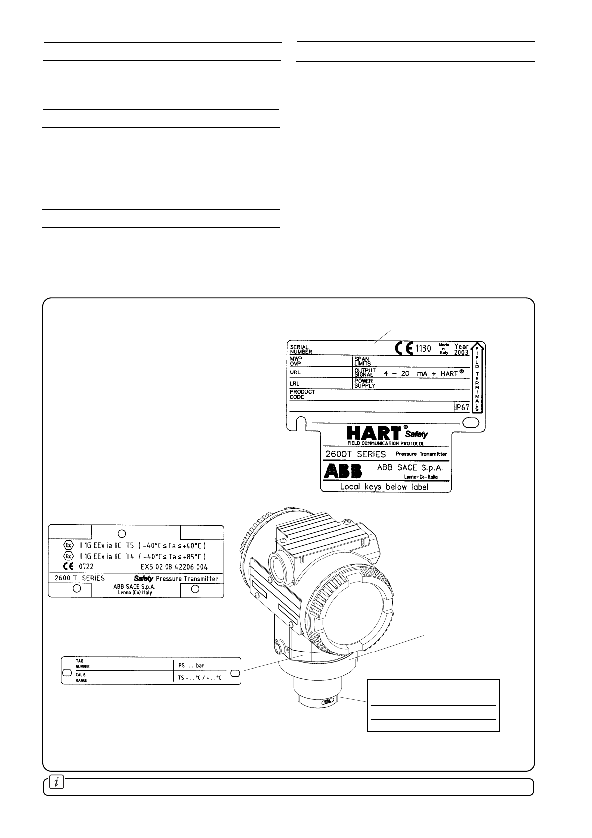
of the present manual. For installation in hazardous areas,
compliancewithsafetyinformationonthesafetymarkingplate
shall be ensured.
Commissioning
Field Instrument Functionality
All the necessary activities to assure that the process sensor
orfinalelementareoperatingtogetherandperformtherequired
function are described in the "Electrical connections" and
"Calibration" sections of the present document.
Overall System Functionality
Theactivitiestovalidatetherequired safetyfunctionalityofthe
system together with the target equipment according to the
SafetyRequirementSpecificationarePre-StartupAcceptance
test section of the present document.
Operation
System Operating Discipline
APlantpolicyguidelinedocumentcontainingthespecificplant
policyguidelineforthedailysafeoperationhastobeproduced
and periodically reviewed by representatives of the Process
Control Service.
Maintenance
Maintenance is defined as the routine activities which are
carried out to detect unrevealed faults.
Preventive and Routine Maintenance
Preventive and routine maintenance activities are defined in
the maintenance section of the present manual.
Function-unit Replacement
In case of hardware failure corrective actions may be carried
out. In case of transmitter replacement all the operations
described in "Electrical Connection", "Calibration" and "Pre-
Startup Acceptance tests" shall be conducted.
All maintenance activities shall be documented in the system
documentation.Possiblesafetycriticalfailuresshallbereported
using the Incident Report process.
Function-unit Repair
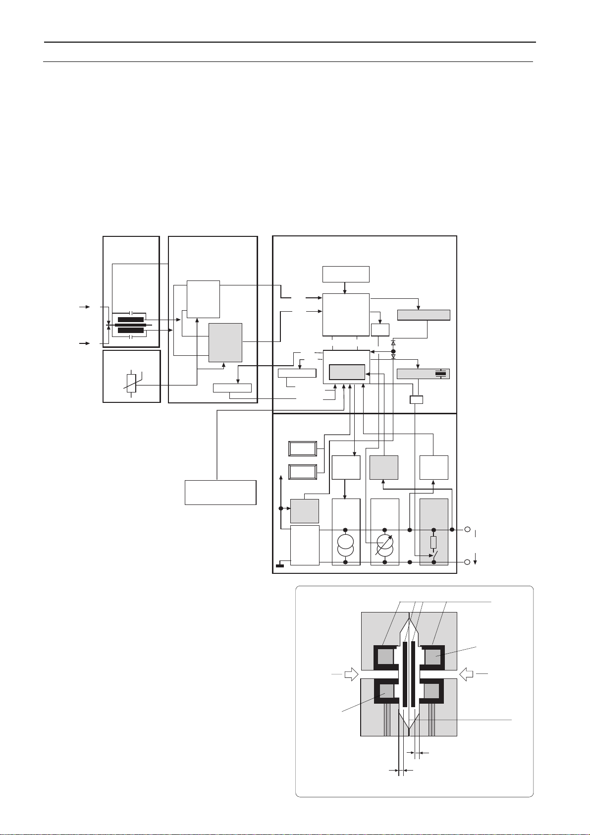
Thetransmitterisconstitutedoftwomainunits(transducerand
electronics). It can be repaired following the information
contained in the Dismantling and Reassembly section of the
present manual.
Central repair shall maintain a record of detected failures,
calculate actual failure rates and compare with the expected
failure rate. Extensive failure rates shall be communicated to
the supplier.
Modification Request
Request of modification due to possible safety critical failures
and performance deviations shall be reported to the factory.
Modificationsshallfollowthecompanymodificationprocedures.
Management of Change
All process changes or SIL category change shall follow the
procedures defined in the safety life-cycle of the system and
shall be reviewed and validated by the external competent
body for a new functional safety assessment.
Management of change Process Components and Roles
Each process component needs to be defined in details
accordingtotherequirementsandtherelevantdocumentation.
Each process component change shall follow the activities
defined in the overall safety life cycle.
Management of change Documentation and Training
Requirements
TheManagementofChangeprocessshallfollowdocumentation
andtrainingrequirementsdefinedinthesystemimplementation.
. . . . LIFE-CYCLE ACTIVITIES

- 8 -
FAULTS OUTSIDE THE FUNCTIONAL SAFETY
The redundant algorithms and the electronics are designed to detect all the internal hardware faults therefore the transmitter
diagnostic is not able to detect faults related to the process and to the installation configuration. In the following table the known
weaknesses resulting from the transducer FMEA (Failure Mode and Effect Analysis) are listed.
Assembledmaterialatthepipesofthetransmitter,
blockage of pipe.
Applicationoutside specified temperaturerange.
Excess of temperature
Assembledgasatthetransmitter,if thetransmitter
is mounted above the process line
Overload pressure, high peak pressure pulses in
process lines
Penetration of hydrogen, diaphragm crack in
applications with hydrogen process medium.
Thin walled diaphragm, leaky diaphragm in
applications with abrasive medium.
Thin walled diaphragm, leaky diaphragm in
applications with corrosive medium.
Higher diaphragm stiffness, crack in application
with contamination of metal ions
Mechanical damage through cleaning, damage
of the coating, corrosion.
Other considerations
The alarm levels of the transmitter (down-scale or up-scale)
can be selected by the user. For some faults (e.g. crystal
breakdown), the output will latch at 22 mA even if the down
scale alarm level is selected.
failure failure effect Comments
∆p-level
measurement is wrong
wrong measurement
insensitive, wrong
measurement
wrong measurement after
compression stress
insensitive measurement,
breakdown
wrong measurement,
breakdown
wrong measurement,
breakdown
insensitive
measurement
faulty or insensitive
measurement,breakdown
Piping should be periodically
inspected and cleaned.
The transmitter should operate
inside the specified temperature
ranges.
Transmitter should be installed
properly as specified in this
manual.
The transmitter should operate
inside the specified temperature
ranges.
Hydrogenserviceallowedwiththe
application of a special grace on
diaphragms or by using gold
plated diaphragms.
Transmitter manual specifies the
preventiveperiodicmaintenance.
Appropriate materials should be
selected for corrosive
applications.
Appropriate materials should be
selected for particular
applications.
Transmitter manual specifies
correct maintenance
procedures.

- 9 -
The instrument consists of two functional units:
- Primary Unit
- Secondary Unit
The Primary Unit includes the process interface and the
sensor,theSecondaryUnitincludestheelectronics,theterminal
blockandthehousing. Thetwounitsaremechanicallycoupled
by a threaded joint. All units are based on custom integrated
components (Application Specific Integrated Circuit - ASIC).
TheprincipleofoperationofthePrimaryUnitisasfollows.The
process fluid ( liquid, gas or vapour ) exerts pressure on to the
measuringdiaphragmviaflexible,corrosion-resistantisolating
diaphragm and the fill fluid (see Fig. 2a). The other side of the
measuring diaphragm is either at "atmosphere", for gauge
measurement, or at "vacuum", for absolute measurement. As
themeasuringdiaphragmdeflectsinresponsetoinput pressure
changes, it simultaneously produces variations in the gap
between the magnetic disc and the magnetic core of the coil,
whichismountedrigidlyontotheprimarybody. Asaresult,the
inductance of the coil changes.
The inductance values of the coil is compared to that of a
reference inductor carried by the primary electronics.
PRINCIPLE OF OPERATION
Theunitalsoincludesatemperaturesensor.Thetwoinductance
values and the sensor temperature, are combined in the
primary electronics to provide a proprietary standard signal.
Consequentlythefurtherelaboration,togetherwithtemperature
signal is equivalent allowing to use the same secondary
electronics.
Inthemanufacturingprocessthesensoroutputcharacteristics
arecomparedwithreferencepressuresandtemperatures:the
"mapped" parameters are then stored in EEPROM # 1.
Themeasuredvaluesandthesensorparametersaretransferred
to the Secondary Unit, where a microprocessor computes
precise primary output linearisation, compensating for the
combined effects of sensor non linearity and temperature
changes. In the secondary electronics EEPROM #2 stores
specific transmitter information:
- non modifiable data such as the serial number, the UID
(UniqueIdentifier),themanufacturer'snameanddevicetype,
the hardware and software version of the electronics.
- themodifiable datasuch asthe finaltrimming andcalibration
ie., all data that can be changed by the user through the
configurator devices.
External Zero/Span
adjustments
Fig. 2b - Secondary Unit
Output meter
(option) Surge protector
(option)
Terminal
block
Housing Electronics
RFI filter
Fig. 2a - Primary Unit
Primary Electronics
Printed Circuit
Process
connection
Sensor Diaphragm
Inductance Coil
& Magnetic Core
Ferrite disc
Isolating Diaphragm
Reference chamber
Input

- 10 -
. . . PRINCIPLE OF OPERATION
2600T Safety Transmitter takes advantage of the intrinsic
redundancy of the 2600T series differential inductive sensor.
The two inductive signals are separately detected in the
primary unit by two independent ASICs and separately
elaborated internally to the electronics. Calculations follow
independentflowsandtheyarecomparedinthemicrocontroller
in order to validate the output pressure signal. If a difference
between the two measurements is detected the analog output
is driven to a safety condition. Internal diagnostics algorithms
are implemented to check correctness and validity of all
processing variables and the correct working of memories.
Asupplementaryshutdowncircuitryprovidesasafeshutdown
whenafaultoccursintheanalogsectionoftheelectronics.The
outputstageisalsocheckedbyreadingbacktheanalogoutput
signal. The feedback loop is obtained by an additional A/D
converter put at the end of the output stage, which translates
the 4-20 mA signal into a digital form suitable to be compared
by the microcontroller.
Pressure Sensor
The pressure sensor gives the primary input signal to the
electronics. The input pressure is converted in a (micro)
displacement"d"ofametaldiaphragm(measuringdiaphragm)
whose stiffness determines the URL of the sensor. The
diaphragm displacement changes the gap of a magnetic
circuit,generatingthevariationoftheinductivepick-updetector
constituted of two inductances called L1 and L2. One of the
inductance values increases the other decreases. The
inductance value is measured by forming an oscillator with an
extra capacitor (C1,C2). The oscillation is excited by a pulse
and simultaneously measured by two ASIC5 (see the picture
above).Thefundamentalfrequencyofoscillationrelatestothe
inductance values with the following law: (T=2PI*SQR(LC)).
Temperature Sensor
The temperature sensor measures the temperature of the
pressure sensor. The resulting value is used by the µP for
temperature compensation purposes.
SAFETY 2600T Pressure Transmitters
block diagram
Pressure sensor
Ferrite
L2
L1
P2
P1
Measuring
diaphragm
d1 (gap)
d2 (gap)
ASIC5
(trigger
and
reading)
Primary
Electronics
EEPROM
EEPROM
A/D
converter
ASIC7
µP
Secondary
Electronics "µP"
ASIC5
(only
reading)
T5 Generator
+0.33% / °C
1.watchdog
2.watchdog
&
L1
L2
P1
P1
Pressure
Sensor
Temperature
Sensor
PWM
Filter
TX2
TX1
CE2
CE1
Calibration
Parameter
Sensor
Parameter
Display
Reset
Reset
HART
modem
Tx
4...20 mA
reading
HART
modem
Rx
over-
voltage
detection
DC/DC
Converter
GND
const.
current
generator
3.6 mA
const.
current
generator
0.4...16.4
mA
second
shut
down
>20 mA
4...20 mA
10.5...42 V
Key
Span
Key
Zero
Secondary
Electronics "PS"
VCC
D0...7 A0...9
HARDWARE DESCRIPTION
General hardware description
The electronic hardware structure is described in the following figure.

- 11 -
. . . PRINCIPLE OF OPERATION
Primary Electronics
Mainpurposeofthis unitisto convertthepressure signaltoan
electronicpulse-width signal.As helpfor addedaccuracyboth
temperatures and static pressure of the transducer are
measured.
ASIC5
TheASIC5componentscontainthebasicpulsewidthconverters
thatconverttheinput frequencycomingfrom thesensorin two
redundantpulse-widthsignalsproportionaltothetwoinductance
values L1 and L2. The two independent output time-duration
signals from ASIC 5 are applied to the secondary unit through
independent lines.
EEPROM1 Memory
This EEPROM memory is used by the "µP" described later. It
contains all the relevant information for the sensor
characterization and for the transmitter calibration.
Secondary Electronics "µP"
ThisunitusesaµPandanASICtoconvertthebasicmeasured
data into correct scaled data. Compensation for temperature
and static pressure are also performed. The output data value
is converted into a pulse-width signal that is filtered and that
activates the 4-20 mA transmitter. The bi-directional, digital
communication using the standard “HART” protocol is
implemented as part of this unit.
ASIC7
The main input to ASIC7 are the two independent pressure
signalscombinedontwolinesfromASIC5calledTX1andTX2.
The ASIC7 converts in two independent counter sections the
pulsewidthstotwosetsoffive24bitsnumbers(A/Dconversion).
The pulse-width information are stored in two different RAM
locations and used by the µP to perform all the necessary
calculations and consistency checks and to calculate the
compensated output with correct scaling. Afterwards the µP
writes the calculation results into two 8 bit registers in ASIC7.
Watchdog1
A watchdog function is implemented in the ASIC7. It interacts
withtheµP viatheResetblockdescribed later.Incaseof error
at first the watchdog resets the µP. After three retries it drives
the PWM output in alarm condition (UP/DOWN scale).
HART Modem
A modem circuit for demodulation is implemented in the ASIC
both for receiving and transmitting.
µP
TheµPperformsallthecalculationsandthediagnosticfunctions.
It drives also the supplementary shut down in case of errors in
the analog part.
Reset
There are four reset functions for the µP. “Power On Reset”,
reset on ASIC7 request as described above and reset on
power supply too low or too high.
PWM Filter
This first order RC filter gives an average value of the pulse
width signal from ASIC 7.
T5 Time Generator
TheASIC7generatesatemperaturedependentcurrent(+0.33%
/ °C) applied to the T5 generation circuit that provides a time
duration signal (T5) used to measure the temperature in the
secondary electronics.
Watchdog2
A secondary watchdog is used to monitor the correct working
of the main clock. In case the main clock doesn't work it gives
asignaltothesupplementaryshutdownlogicblockthatprovides
to force the output in safety condition.
4-20 mA reading
The internal microprocessor 8 bit A/D converter provides to
convert to a digital value the analog feedback signal from the
4÷20 mA output current loop. The obtained value is internally
compared with the digital value of the actual output current for
diagnostic purposes.
EEPROM2 Memory
The EEPROM2 memory is used by the µP to store and read
configuration data and data concerning calibration of the 4-20
mA generator.
Secondary Electronics "PS"
This unit contains the 4-20 mA transmitter, the power supply
and the basic analog part of the “HART” protocol.
Constant Current Generator 0-16 mA
This block converts the filtered DC voltage representing the
pressureintoa0-16mAcurrent.Theblockistrimmedtogether
withthepowersupplytomaintainthestable4mAbasiccurrent
making the total current 4-20 mA.
Constant Current Generator 3.6 mA
This block generates a stable current basically close to 4 mA.
ThecurrentgeneratorisalsousedbytheHARTprotocolinthe
transmitmodetogenerate a+/-400µA current.Externallythis
will generate a +/- 100 mV signal across a 250 ohm minimum
resistor.
Local keys
The pressure transmitter has two screws hidden under the
nameplate. They can be used for setting ZERO and SPAN
valuesintheunit.Thescrewsturnamagnet,thatclosesareed
rely,thatactivatestheµP.TheZEROgivesthepresentsensor
value as the reference point. The SPAN gives the present
sensor value as FULL SCALE value. The screws with the
magnet can be removed to prevent unauthorized changes.
DC/DC converter
The input voltage is stabilized and regulated with a DC-DC
converter to provide the circuit power supply.
HART Rx
TheHARTmodemreceivingdataarepre-filteredandbuffered
in this block.
Over voltage detection
The power supply is continuously monitored. In case the
voltage exceeds a fixed dangerous value a reset command to
the microprocessor is generated.
Second shut-down
Anadditionalcurrentgeneratorinparalleltotheoutputregulator
allowshavinganindependentshutdownoftheoutputsignal.In
case of a failure of the microprocessor due to a clock failure or
ofa failure in the analog outputstage the second shut-down is
activated forcing in this way the output signal to the up-scale
alarm value.
4÷20 mA reading
A buffer amplifier connected to the microcontroller reads a
voltage in the analog output stage proportional to the PWM
filtered voltage. It constitutes a feedback signal of the output
current.
Display
Optional. Not Safety relevant.

- 12 -
INSTALLATION
CAUTION- Proper location of the transmitter with
respectto the processpipe willdepend upon theservice for
which the instrument is used. Care should be exercised to
identify correct process connections.
The secondary unit of the transmitter may be rotated through
360°approx. with respect to the primary unit without degrading
performance or damaging the internal wiring. Do not force the
primaryunit torotate; usethe2mm Allen keysupplied tounlock
andlockthe tanggrub screw(see Fig.7).This feature,obtained
by unscrewing (one turn is sufficient) the Allen screw, is
particularly useful for reaching optimum access to the electrical
connections and visibility of the output indicator.
WARNING - In order to ensure operator safety and
plant safety it is essential that installation is carried out by
suitably trained personnel according to the technical data
providedintheDataSheetfortherelevantmodelincluded
in the supplementary documentation, in particular in the
"Operative limits" section.
The transmitter may bemountedona 2-inchpipe(figg. 4,5a,
5b, 5c, 6a and 6b) by means of the proper mounting bracket.
The transmitter may also be directly, supported by the piping
connection.
Fig. 4 - Mounting on pipe
Fig. 5a
WARNING - For installation in Hazardous Areas,
i.e.areas with dangerous concentrations of e.g. gasesor
dusts that may explode if ignited, the installation must be
carriedoutinaccordancewithrelativestandardseitherEN
60079-14 or IEC 79-14 and/or with local authority
regulations, for the relevant type of protection adopted.
Together with safety information here and after enclosed
see also the Addendum for "Ex Safety" aspects which is
part of this instruction manual.
WARNING: The transmitter when installed in
accordance with this instruction manual will not be
subjected to mechanical stresses.
WARNING: the transmitter should not be installed
where it may be subjected to mechanical and thermal
stresses or where it may be attached by existing or
foreseable aggressive substances.
ABB cannot guarantee that a construction material is
suited to a particular process fluid under all possible
process conditions. See also the paragraph on "Operati-
ve limits".
1/2in - 14 NPT female connection
Note: dimensions are expressed in mm. (Between parenthesis the same dimensions expressed in inches).
86 (3.39)
CH 32
S
N
O
S
S
T
I
U
C
R
I
C
S
E
L
N
O
I
N
E
T
S
O
S
T
U
R
R
E
V
U
O
C
E
L
R
E
D
R
A
G
T
N
E'
M
E
F
N
E
B
E
L
C
I
Q
U
A
T
E
A
L
S
T
I
U
C
R
I
C
I
V
E
H
C
O
P
E
E
K
V
E
R
T
I
G
T
E
H
W
N
!
18 (0.71) 100 (3.94)
ø 65 (2.56)
135 (5.31)
16 (0.63)
57 (2.24)
127 (5.00)
17 (0.67) 17 (0.67)
36 (1.42)
19 (0.75)
36 (1.42)

- 13 -
DIN–EN837–1 G 1/2in B connection
86 (3.39)
CH 32
S
N
O
S
S
T
I
U
C
R
I
C
S
E
L
N
O
I
N
E
T
S
O
S
T
U
R
R
E
V
U
O
C
E
L
R
E
D
R
A
G
T
N
E'
M
E
F
N
E
B
E
L
C
I
Q
U
A
T
E
A
L
S
T
I
U
C
R
I
C
I
V
E
H
C
O
P
E
E
K
V
E
R
T
I
G
T
E
H
W
N
!
18 (0.71) 100 (3.94)
135 (5.31)
16 (0.63)
G 1/2"B
57 (2.24)
42 (1.65)
ø 17.5 (0.69)
ø 65 (2.56)
57 (2.24)
127 (5.00)
17 (0.67) 17 (0.67)
36 (1.42)
1/2 in – 14 NPT male connection
86 (3.39)
CH 32
S
N
O
S
S
T
I
U
C
R
I
C
S
E
L
N
O
I
N
E
T
S
O
S
T
U
R
R
E
V
U
O
C
E
L
R
E
D
R
A
G
T
N
E'
M
E
F
N
E
B
E
L
C
I
Q
U
A
T
E
A
L
S
T
I
U
C
R
I
C
I
V
E
H
C
O
P
E
E
K
V
E
R
T
I
G
T
E
H
W
N
!
86 (3.39)
S
N
O
S
S
T
I
U
C
R
I
C
S
E
L
N
O
I
N
E
T
S
O
S
T
U
R
R
E
V
U
O
C
E
L
R
E
D
R
A
G
T
N
E'
M
E
F
N
E
B
E
L
C
I
Q
U
A
T
E
A
L
S
T
I
U
C
R
I
C
I
V
E
H
C
O
P
E
E
K
V
E
R
T
I
G
T
E
H
W
N
!
57 (2.24)
ø 65 (2.56)
18 (0.71) 100 (3.94)
135 (5.31)
16 (0.63)
1/2" - 14 NPT
ø 65 (2.56)
57 (2.24)
127 (5.00)
17 (0.67) 17 (0.67)
36 (1.42)
39 (1.54)
54 (2.13)
18 (0.71) 100 (3.94)
16 (0.63)
ø 41.3
ø 65 (2.56)
135 (5.31)
17.5 (0.69)
127 (5.00)
17 (0.67) 17 (0.67)
36 (1.42)
34 (1.34)
. . . INSTALLATION
Adapter straight (180°) entry connection (7/16in – 20 UNF drilling)
Fig. 5b
Fig. 5c
Fig. 6a

- 14 -
. . . INSTALLATION
Fig. 6b
Adapter angle (90°) entry connection (7/16in – 20 UNF drilling)
86 (3.39)
S
N
O
S
S
T
I
U
C
R
I
C
S
E
L
N
O
I
N
E
T
S
O
S
T
U
R
R
E
V
U
O
C
E
L
R
E
D
R
A
G
T
N
E'
M
E
F
N
E
B
E
L
C
I
Q
U
A
T
E
A
L
S
T
I
U
C
R
I
C
I
V
E
H
C
O
P
E
E
K
V
E
R
T
I
G
T
E
H
W
N
!
ø 65 (2.56)
18 (0.71) 100 (3.94)
49.5 (1.95)
ø 41.3
(1.63)
ø 39 (1.54)
135 (5.31)
31 (1.22)
127 (5.00)
17 (0.67) 17 (0.67)
36 (1.42)
16 (0.63)
42.5 (1.67)

- 15 -
WARNING - For installation in Hazardous Areas,
i.e. areas with danger of fire and/or explosion, prior to
making electrical connections, ensure compliance with
safetyinformationontheSafetyMarkingplate.Failureto
comply with this warning can result in fire or explosion.
Signal terminals are located in a separate compartment of the
secondary unit housing. The housing incorporates two con-
nection ports for cable glands or conduit fittings. They are
protected with a temporary plastic plug for transit purpose
whichshouldbereplacedwithasuitablepermanentpluginthe
unusedport. Connectionscanbemadebyremovingthecover
(indicatedinFig.7);firstscrewdownthelockingscrew located
below the cover, using a 3 mm Allen Key.
WARNING - For Hazardous Areas installations,the
connection of cables and conduits to the transmitter shall
be made in accordance with the requirements of the
relevanttypeofprotection. Cablesandcable-glandsmust
be in accordance with the type of protection.
Unused openings for connection shall be closed with
blanking elements suitable for the relevant type of
protection. With the exception of intrinsically safe
transmitters,themeansprovidedforthisshallbesuchthat
the blanking element can be removed only with the aid of
tools.Theblanking elementsmustbe certifiedforthe type
of protection. See standards either EN 60079-14 or IEC
79-14. The transmitter connections must also guarantee
the degree of protection of the transmitter enclosure, e.g.
IPxx according to EN 60529 standard (or IEC529). See
also the Addendum for "IP" protection (and Ex Safety)
which is part of this instruction manual.
Thesignalcable shouldbeconnected totheterminals marked
respectively (+) and (-). If an internal output meter - either with
analog or digital indication - is installed, it should be removed
inordertomaketheconnection,simplybypullingitoutfromits
socket. After the connections have been made, reinstall the
output meter. Refer to the Meters Option addendum for
details.
The power to the transmitter is supplied over the signal wiring
and noadditionalwiringis required.Thesignalwiringdoesnot
need to be shielded but the use of a twisted pair is highly
ELECTRICAL CONNECTIONS
recommended. The cable shield should be grounded in one
side only, to avoid dangerous earth paths.
WARNING - For Hazardous Areas installations,
when the ambient temperature is higher than 70°C, the
cable used for the connections must be suitable for 5°C
above the ambient temperature.
Normal practice is to ground in the control room side, in which
case the field side of the screen should be adequately
protected to avoid contact with metallic objects. Signal wiring
may be ungrounded (floating) or grounded at any place in the
signalloop,but forintrinsically safeinstallationsthe wiringand
groundingmustfollowthespecificrulesforthistechnique. The
transmitter case may be grounded or ungrounded: a ground
connectionisprovidedinternally(intheterminal compartment)
and externally.
Do not run the signal wiring in close proximity to power cable
or high power equipment; use dedicated conduits or trays for
signal wiring.
CAUTION - Do not connect the powered signal
wiring to the mA signal testing terminals as this could
damage the by-pass diode.
Aftertheconnectionshavebeencompletedchecktheintegrity
of the cover O-ring, screw down the cover and secure it by
unscrewing the safety screw.
CAUTION - Unless absolutely necessary, avoid
theremoval onsite ofthe protectivecover whichgives
accesstotheelectroniccircuitry.Althoughtheelectro-
nicsare fullytropicalized they shouldnot be subjected
to humidity for long periods.
WARNING - For Hazardous Location
installations, at least eight (8) threads on each cover
must be engaged in order for the transmitter to meet
(FLAME PROOF - explosion-proof) requirements.
Fig. 7 - Location of the locking screws and terminals
Grub screw
Secondary Unit
Cover locking
screws (in the
position indicated
by the arrows)
Primary Unit
Remove this
cover to
access
terminals
M
TEST COMM
Hand Held Communicator
Terminals
Test Terminals
Output
Meter
Socket
Ground Terminal
Signal Terminals
Fig. 8a - Terminals arrangements
Short
circuit link

- 16 -
. . . ELECTRICAL CONNECTIONS
WARNING : DO NOT ATTEMPT TO CONNECT
AN AMPEROMETER BETWEEN A "TEST" TERMINAL
AND A "COMM" TERMINAL. THE RESULT TO THE
POWER SUPPLY IS A SHORT WHICH WILL BLOW
FUSESANDPOSSIBLYDAMAGEYOUREQUIPMENT,
ALSO CAUSING TO INTERRUPT FUNCTION OF
OTHER DEVICES POWERED FROM SAME SUPPLY.
NOTE: If the use of the Hand Held Communicator is
foreseen, a resistance of 250 ohms minimum must be
includedinthecurrentloop,betweenthepowersupplyand
the connection point of the Hand Held Terminal, for
communication purpose.
Here below is given an explanation regarding the possible
connection of the terminal block to the power supply and a
representation of the connection in case of remote indicator
presence (See fig. 8b and 8c).
Fig. 8b - Electrical connections
Fig. 8c - Electrical connections with remote indicator
+
+
-
-
+
+
-
-
Line load
GND
Hand-held
communicator
Power
source
Optional
Receiver
Test points
4-20 mA
250 ohm min
Internal ground
termination point
691HT
A B C
1D E F
2G H I
3
J K L
4M N O
5P Q R
6
S T U
7V W X
8Y Z #
9
@ %
& /
0+
-
PV
REVIEW SERIAL
LINK
TRIM
F1 F2 F3 F4
CONF
External ground
termination point
M
TEST COMM
+
+
-
-
+
+
-
-
Line load
GND
Hand-held
communicator
Power
source
Optional
Receiver
Test points
4-20 mA
250 ohm min
Internal ground
termination point
Remote indicator
691HT
A B C
1D E F
2G H I
3
J K L
4M N O
5P Q R
6
S T U
7V W X
8Y Z #
9
@ % & /
0+
-
PV
REVIEW SERIAL
LINK
TRIM
F1 F2 F3 F4
CONF
External ground
termination point
M
Kent-Taylor
0
4
3
5
6
7
8
9
10
20
40
0
60
100
%
2
80
M+
-
TEST COMM
Model 691HT Communicator
may be connected at any wiring
termination point in the loop,
providing the minimum
resistance is 250 ohm.
If this is less than 250 ohm,
additional resistance should be
added to allow communications.

- 17 -
ELECTRICAL REQUIREMENTS
Thetransmitteroperatesonaminimumvoltageof10.5Vdcto
a maximum of 42 Vdc and is protected against polarity
inversion.
Note - Thetransmitter operates from10.5 to 42 Vdc
with no load (additional load allows operation over 42
Vdc). For EEx ia and intrinsically safe approval power
supply must not exceed 30 Vdc.
In some countries the maximum power supply voltage is
limited to a lower value.
Installing optional devices the minimum voltage increases to:
- 10.5 Vdc with no option
- 10.7 Vdc with output analog indicator
- 12.5 Vdc with LCD ProMeter
- 12.3 Vdc with surge protection
- 13.3 Vdc with LCD CoMeter
- 15.3 Vdc with no link on output indicator plug
Thetotal loopresistanceis indicatedin theexpression below.
The Smart 600T EN Transmitter Specification Sheets provide
allinformationconcerningtheRangeandSpanlimitsinrelation
to the model and the sensor code.
The terminology currently used to define the various
parameters is as follows:
URL : Upper Range Limit of a specific sensor. The highest
value of the measured value that the transmitter can be
adjusted to measure.
LRL:LowerRangeLimitofaspecificsensor.Thelowestvalue
of the measured value that the transmitter can be adjusted to
measure.
URV : UpperRangeValue.Thehighestvalueofthemeasured
value to which the transmitter is calibrated.
LRV : LowerRange Value.Thelowest valueof themeasured
value to which the transmitter is calibrated.
SPAN : ThealgebricdifferencebetweentheUpperandLower
Range Values. The minimum span is the minimum value that
canbeusedwithoutdegradationofthespecifiedperformance.
TURNDOWNRATIO: istheratiobetweenthemaximumspan
and the calibrated span.
The transmitter can be calibrated with any range between the
LRL and the URL with the following limitations:
LRL ≤LRV ≤(URL - CAL SPAN)
CAL SPAN ≥MIN SPAN
URV ≤URL
RANGE AND SPAN CONSIDERATION
The total loop resistance is the sum of the resistance of all
elements of the loop, including wiring, conditioning
resistor,safetybarriersandadditionalindicators(excludingthe
equivalent resistance of the transmitter).
Where a configuration device (HART), such as the Hand Held
Communicatoror aModem islikely tobe used, aresistance of
250 ohm minimum should be present between the power
supply and the point of insertion of these devices, to allow
communication.
Severaltypesofsafetybarriers,eitherpassiveoractive,canbe
satisfactorily used in conjunction with the Smart 2600T
transmitters. Nevertheless, in case of use of active barriers,
check with the supplier if the model is suitable for use with
smarttransmittersallowingtheconnectionoftheconfiguration
devices in the "safe" or non-hazardous area.
TRANSMITTER OUTPUT SIGNAL
The 2600T Safety transmitter provides both the analog 4÷20
mAandthedigitalHARTcommunication.HARTsignalsdonot
affect safety during trading operations. HART writings are
permitted only in maintenance (out of safety) condition.
Analog Signal
Two-wire 4 to 20 mA dc, user-selectable for linear or square
root output; power of 3/2 or 5/2, 5th order or two 2nd order
switching point selectable programmable polynomial output
can be also selected for version with HART communication.
HART Signal
Digital process variable (%, mA or engineering units)
superimposedonthe4to20mAsignal,withprotocolbasedon
Bell 202 FSK standard.
Output current limits (compliant to NE 43 NAMUR
regulation)
Overload condition:
- Lower limit 3.8 mA dc
- Upper limit : 20.5 mA dc
R (kΩ) = Supply voltage - min. operating voltage (Vdc)
22.5
Transmitter failure mode (compliant to NE 43 NAMUR
regulation)
Theoutput signal canbe user-selected toa value of 3.7or 22
mA on gross transmitter failure contition, detected by self-
diagnostics.
WARNING - The transmitter may be used as a
safety accessory (as defined by the Pressure Equipment
Directive 97/23/EC) i.e. as part of a shutdown system.
In this case it is recommended to select the correct fail
safe mode for the 4-20 mA signal (as per Namur NE43
recommendation).
See also the instructions relevant to fail safe selection
(Up/Downscalemode)intheaddendumtotheinstruction
manual on "Use of hardware links on the secondary
electronics" .

- 18 -
The 600T Safety transmitters contain inside its non-volatile
memories a number of parameters. Some of them, factory
defined, are typical of the sensor and are not user-modifiable,
theotherareconfigurationparametersandcanbemodifiedby
the user.
During the normal operation status, with the transmitter in
safety conditions, all remote and local configuration shall be
COMMISSIONING AND CONFIGURATION ISSUES
The transmitter is considered in safety condition (normal
operatingmode)whentheswitchisinWriteProtect(off).Inthat
condition only reading commands are enabled. The special
procedure which shall be performed to put the transmitter in
operating mode is described in the following section.
Operating mode enabling and disabling
Operating mode can be enabled/disabled depending on
Switch 5 (Write) position at power on condition. The switch is
located on the secondary electronics unit under the housing
cover. To ensure safety operations of the device a specific
HART command shall be performed in order to enable the
condition changes.
disabled. The Safety 2600T pressure transmitter is protected
against undesirable configuration changes by a dedicated
hardwarelinkplacedonthesecondaryelectronicsboardwhich
is identified as Write Protect Mode Link (see fig. 9).
The following figure described the maintenance-operating
philosophy:
(Switch 5)
Write Protect Mode
link position at Start-up
(power on)
Transmitter
status Operations required to pass to the
opposite condition
1. Switch in OFF position
2. HART Command ("Change transmitter status to
operating") or Power OFF/Power ON
1. Switch in ON position
2. HART Command ("Change transmitter status to
maintenance") or Power OFF/Power ON
ON
OFF
Maintenance
Operating
Table 1
WARNING - After any configuration operation, the transmitter must be put in operating condition as described
in Table 1. During this change a software reset is performed and the transmitter is not working for few seconds.
COMMISSIONING
/ MAINTENANCE OPERATING
HART
Read - Write
Command
HART Read
Command
Reset & Dip Switch Write Protect Mode = OFF HART command &
Dip Switch Write Protect Mode = OFF
Local Key
Read-Write
Operation
and read
UP-DOWN SCALE
Dip Switch
HART command &
Dip Switch Write Protect Mode = ON /
Reset SW and
Read UP-DOWN SCALE Dip Switch
Reset & Dip Switch Write Protect Mode = ON /
Read UP-DOWN SCALE Dip Switch
Configuration enable/disable switch modeled by Finite states machine
Upscale/Downscale
link
5 6
Write Protect
Mode link

- 19 -
CALIBRATION
Set up an appropriate test rig in accordance with the required
calibration. Figure 11 shows a complete test rig that can be
selectively used to suit the calibration.
Notethatcalibrationaccuracyisstrictlyrelatedtotheaccuracy
ofthe test equipment: theuse ofa dead weighttester is highly
recommended.
The zero and span calibration screws are located behind the
Nameplate.Togain accessslacken the nameplatescrew and
rotate 90°; proceed in the reverse mode when the calibration
procedure has been completed. Fig. 12 shows the calibration
screws:they providetwolargeplasticheadsthatcanrotate90°
in the direction indicated by the arrows, with spring-return to
normal. The calibration screws can be removed after the
calibration, to avoid improper use by inserting a screwdriver
blade below the plastic flange and pulling out.
Fig. 12 - Top view of the calibration devices
M1 - Pressure gauge
Fig. 11 - Calibration pressure connections
M1
A
Pressure Generator or
Dead Weight Calibrator
V.G.
V.P.
B
V.G. - Vacuum Gauge
V.P. - Vacuum Pump
Fig. 9 Location of the links on the electronics
Unlike conventional electronic transmitters, the use of a
microprocessor and the presence of serial communications
betweenthetransmitterandtheconfigurationdevice,allowsthe
use of several different approaches in calibration and servicing.
DifferentmethodscanbeusedtocalibratetheSafetytransmitter:
i) using the zero and span calibration screws in the
transmitter secondary unit.
ii) using the Hand Held Communicator.
iii)using the Personal Computer Configuration Software
Package.
This chapter describes the first method; the others are
described next or in the relevant Instruction Manuals of
configurationtools. Ifthecalibrationscrewsarenotfitted
calibration must be done by method ii) or iii).
Inthe Safety2600T Series itis alsopossible toapply a scaling
to the reading of the transmitter.
The operation is called PV-scaling and is used to align the
"zero"of theprocess withthe "zero"reading of thetransmitter.
SeethedescriptionintheAddendum forPVscalingoperation.
Note: Unless otherwise specified the instrument is
factorycalibratedatmaximumspanwiththeLRVsettotrue
zero. Instruments adjusted and tagged for a specific range
willnotrequirerecalibration.Rezeroingofthetransmitter
may be required in order to compensate for zero shift
arising from the installation.
Preliminary operation
Before commencing calibration ensure that:
i) therequiredspan, theupperand lowerrangevalue (URV&
LRV) are within the span and range limits (URL & LRL)
indicated on the nameplate (please refer to "Range and
Span" consideration on the previous page).
ii) the transmitter is properly powered and the electrical
connections correctly made.
iii) the Write Protect Mode link, located on the electronics
module is in position ON (write allowed). Access to the link
is gained by unscrewing the secondary unit housing cover
at the opposite end to the terminal cover (See Fig. 9).
iv)the Upscale/Downscale link is positioned to the required
function: ON for Downscale OFF for Upscale (see Fig. 9).
v) make the electrical connections, as indicated in Fig. 10.
Connect a precision milliammeter as shown and remove the
short circuit link.
Upscale/Downscale
link
5 6
Write Protect
Mode link
The calibration screws can be of type "Push buttons" with
exactly the same functionality; keep it pressed for at least two
seconds.
Precision
Milliameter
Power Supply
10.5 to 42 V. d.c.
Short circuit link
Fig. 10 - Calibration electrical connections
M
TEST COMM

- 20 -
. . . . CALIBRATION
In some cases, expecially for tank level measurement, the
calibrationcanalsobeobtainedautomaticallybytheindication
of the actual output percentage, without any calculation for
LRV and URV. The operation is called Output % Reranging
andcanbeperformedusingaHARTconfigurationtool(seethe
ADDENDUM on Output % Reranging).
WARNING. In order to ensure the correct operation
of the transmitter, after the calibration procedure the
devicemustbeput in"OperatingCondition" asdescribed
inTable1,inthesectionCommissioningandConfiguration
issues.
Absolute pressure
Use the zero and span procedure above but apply to the
process connection absolute pressures equal to the Lower
RangeValue(LRV)andthentotheUpperRangeValue(URV),
turning, for at least 1 second, the zero and span screws
respectively.
Zero elevation procedure
Thisprocedureappliestothegaugepressuretransmitter,only.
The zero can be elevated up to a full vacuum.
Apply pressures equal to the LRV (this value is therefore
between the zero gauge pressure and the full vacuum) and
thenequaltotheupperrangevalue(URV)andcorrespondingly
turn the zero and span screws respectively.
Note - If during the calibration procedure the
readings on the digital milliammeter are outside its
inherent accuracy, output trimming of the transmitter
mayberequested.Thisoperationcanonlybeperformed
using the Hand Held Terminal Communicator or the
PersonalComputer Configurator. If this equipment is
not available the transmitter should be returned to a
Service Center for recalibration.
Zero and span - true zero procedure
Gauge pressure
- Set the A-B switch into "A" position
- Switch on the power supply.
- With no pressure applied to the transmitters, the value read
on the digital milliammeter should be 4 mA ; if it is not turn the
zero screw for at least 1 second. After this operation the
reading should move to 4 mA; if no change occurs repeat the
operation.
- Apply a pressure equal to the upper range value (URV) and
allow time for the pressure to stabilize.
-Turnthespan screwfor atleast 1second: afterthis operation
the reading on digital milliammeter should be 20 mA and the
calibration procedure is complete. If no change occurs either
the calibration procedure was not correctly performed or the
span exceeds the limit; correct and repeat the operation.
Absolute pressure
- Set the A-B switch into "B" position
- Switch on the power supply.
- Operate the vacuum pump connected to the transmitter and
draw the maximum possible vacuum obtainable. The value
readonthe digitalmilliammeter shouldbe 4mA; ifit isnotturn
the zero screw for at least 1 second. After this operation the
reading should move to 4 mA; if no change occurs repeat the
operation.
- If the value of the calibration span (URV) is less than
atmosphericpressuregentlyopentheventvalvesoincreasing
the pressure to the Upper Range Value. If the calibration span
(URV)isgreaterthantheatmosphericpressurethensettheA-
Bswitchto"A"positionandgenerateapressurecorresponding
to the URV. Allow time for the pressure to stabilize.
-Turnthespan screwfor atleast 1second: afterthis operation
the reading on digital milliammeter should be 20 mA and the
calibration procedure is complete. If no change occurs the
calibration procedure was not correctly performed or the span
exceeds the limit; correct and repeat the operation.
Zero suppression procedure
Gauge pressure
Two different methods (a) or (b) can be used :
a) After completion of the zero and span procedure above,
applyapressureequaltothepressuretobesuppressed.Allow
time for pressure stabilization and then turn the zero screw for
at least 1 second. After this operation the digital milliammeter
reading should be 4mA and the Upper Range Value
automatically moved to a value equal to the sum of the
pressure to be suppressed and the previous calibrated span.
b)Usethezeroandspanprocedureabovebut apply pressures
equal to the Lower Range Value (LRV) and then to Upper
RangeValue(URV),andturning,foratleast1second,thezero
and span screws respectively.
This manual suits for next models
4
Table of contents
Other ABB Transmitter manuals
Popular Transmitter manuals by other brands

Lectrosonics
Lectrosonics MM400C instruction manual

APG
APG HU-L24 user manual

Emerson
Emerson Rosemount 3101 Reference manual

BBC Bircher
BBC Bircher Swissdoor RFGate 3.1 370046A Original operating instructions

HACH LANGE
HACH LANGE si628 C manual

Becker
Becker Centronic EasyControl EC415A-III Assembly and operating instructions