ABB AquaMaster 3 FET200 User manual

—
ABB MEASUREMENT & ANALYTICS | USER GUIDE | OI/FET200-EN REV. N
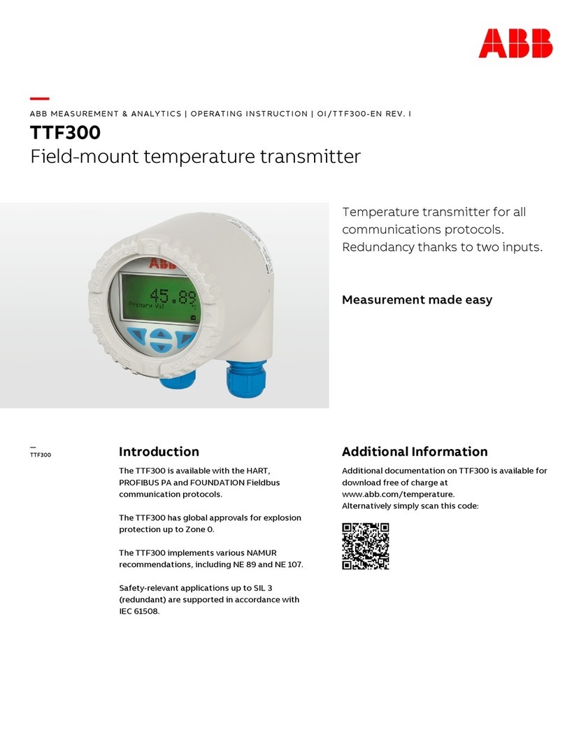
AquaMaster 3 FET200
Electromagnetic flowmeter
transmitter
The smart solution for
remote applications
Measurement made easy
Introduction
AquaMaster 3TM is a range of high
performance electromagnetic flowmeters
for the measurement of electrically-
conductive fluids and is normally supplied
as factory-configured, calibrated systems.
This User Guide provides end-user details
for AquaMaster 3 close-coupled and remote
transmitters.
When the meter is taken out of storage and
installed for first use, remove the protective
label (if fitted) from the front to enable light
to activate the unit.
If the meter is not powered, connect any
batteries or external supply as detailed in
this manual.
For more information
Further publications are available for free
download from www.abb.com/flow or by
scanning this code:
Search for or click on
Data Sheet
Electromagnetic flowmeter
DS/FER200/
FEF200/FEV200–
EN
Data Sheet
AquaMaster
Electronic water meter
DS/AMAS-EN
—
AquaMaster 3
FET200
Electromagnetic
flowmeter
transmitter

AquaMaster 3 FET200
Electromagnetic flowmeter
OI/FET200–EN Rev. N 1
Contents
1 Safety and Security ......................................................................................................................... 3
1.1 Electrical Safety ............................................................................................................................................. 3
1.2 Symbols ........................................................................................................................................................3
1.3 Security .........................................................................................................................................................3
1.4 Health & Safety .............................................................................................................................................4
1.4.1 Battery Hazard, Handling, Shipping and Recycling / Disposal .........................................................5
1.5 Waste Electrical and Electronic Equipment (WEEE) .......................................................................................5
2 Mechanical Installation .................................................................................................................... 6
2.1 Installation Conditions ...................................................................................................................................6
2.2 Fitting the Vandal-Resistant Housing (Integral Transmitters Only) ................................................................... 8
2.3 Dimensions ...................................................................................................................................................9
2.3.1 Remote- and Close-Coupled Transmitter ....................................................................................... 9
2.3.2 Integral Transmitter and Vandal-Resistant Housing .......................................................................10
2.3.3 External Battery Pack ...................................................................................................................10
2.4 GSM-Equipped Transmitters .......................................................................................................................11
2.4.1 GSM Antenna Installation ............................................................................................................. 11
2.4.2 Connecting a Remote Antenna ..................................................................................................... 13
2.4.3 Installing a SIM Card ..................................................................................................................... 13
3 Electrical Installation ..................................................................................................................... 15
3.1 Grounding ...................................................................................................................................................15
3.2 Connections ................................................................................................................................................18
3.2.1 AquaMaster3 Sensor Connections (Remote or Close-Coupled only) ............................................. 18
3.3 Input / Output Connections ......................................................................................................................... 19
3.3.1 Frequency Outputs ....................................................................................................................... 19
3.3.2 Alarm Interface .............................................................................................................................19
3.3.3 Input / Output Connections ..........................................................................................................20
3.3.4 RS232 Local Computer Connection .............................................................................................21
3.3.5 Pressure Transducer (Optional) ..................................................................................................... 22
3.4 Power Supply Connections .........................................................................................................................23
3.4.1 Fitting / Replacing Internal Batteries (Integral Transmitters Only) ....................................................23
3.4.2 External Battery Power Supply ..................................................................................................... 25
3.4.3 Mains Power Supply .....................................................................................................................25
3.4.4 Renewable Energy Supply ............................................................................................................26
4 Start-Up and Operation ................................................................................................................. 27
4.1 Start-up ......................................................................................................................................................27
4.2 Display Activation ........................................................................................................................................ 28
4.3 Display Information ......................................................................................................................................28
4.4 Servicing Plugs and Sockets .......................................................................................................................28
4.4.1 Service Intervals ........................................................................................................................... 28
4.4.2 Equipment Required ..................................................................................................................... 29
4.4.3 Preparation ...................................................................................................................................29
4.4.4 Disconnection ...............................................................................................................................29
4.4.5 Order of Treatment .......................................................................................................................30
4.4.6 Stage 1 – Oxide Removal and Cleaning ........................................................................................30
4.4.7 Stage 2 – Oxide Prevention ..........................................................................................................31
4.4.8 Completion tasks ..........................................................................................................................31
5 Specification .................................................................................................................................. 32

AquaMaster 3 FET200
Electromagnetic flowmeter
2 OI/FET200–EN Rev. N
Appendix A – GSM-Equipped Units, Safety Precautions ..................................................................37
Appendix B Accessories / Spares Kits ...............................................................................................38
B.1 Common accessories ..................................................................................................................................38
B.2 Adapter Cable / Upgrade Kits ......................................................................................................................39

AquaMaster 3 FET200
Electromagnetic flowmeter
OI/FET200–EN Rev. N 3
1 Safety and Security
Information in this manual is intended only to assist our customers in the efficient operation of our
equipment. Use of this manual for any other purpose is specifically prohibited and its contents are not to be
reproduced in full or part without prior approval of the Technical Publications Department.
1.1 Electrical Safety
This equipment complies with the requirements of CEI/IEC 61010-1:2010 'Safety Requirements for
Electrical Equipment for Measurement, Control and Laboratory Use' and complies with US NEC 500 and
Occupational Safety & Health Administration.
If the equipment is used in a manner NOT specified by the Company, the protection provided by the
equipment may be impaired.
1.2 Symbols
One or more of the following symbols may appear on the equipment labelling:
1.3 Security
Warning – Refer to the manual for
instructions Direct current supply only
Caution – Risk of electric shock Alternating current supply only
Protective earth (ground) terminal Both direct and alternating current supply
Earth (ground) terminal The equipment is protected
through double insulation
Important (note)
This product is designed to be connected to and to communicate information and data via a network
interface. It is your sole responsibility to provide and continuously ensure a secure connection between
the product and your network or any other net- work (as the case may be). You shall establish and
maintain any appropriate measures (such as but not limited to the installation of firewalls, application of
authentication measures, encryption of data and installation of antivirus programs) to protect the
product, the network, its system and the interface against any kind of security breaches, unauthorized
access, interference, intrusion, leakage and/or theft of data or information. ABB Limited and its
affiliates are not liable for damages and/or losses related to such security breaches, any unauthorized
access, interference, intrusion, leakage and/or theft of data or information.

AquaMaster 3 FET200
Electromagnetic flowmeter
4 OI/FET200–EN Rev. N
1.4 Health & Safety
Health and Safety
To ensure that our products are safe and without risk to health, the following points must be noted:
The relevant sections of these instructions must be read carefully before proceeding.
Warning labels on containers and packages must be observed.
Installation, operation, maintenance and servicing must only be carried out by suitably trained
personnel and in accordance with the information given.
Normal safety precautions must be taken to avoid the possibility of an accident occurring when
operating in conditions of high pressure and / or temperature.
Chemicals must be stored away from heat, protected from temperature extremes and powders
kept dry. Normal safe handling procedures must be used.
When disposing of chemicals ensure that no two chemicals are mixed.
Safety advice concerning the use of the equipment described in this manual or any relevant hazard
data sheets (where applicable) may be obtained from the Company contact details on the back cover,
together with servicing and spares information.
Warning.
Installation and maintenance must be carried out only by suitably trained personnel.
Read all relevant sections of this manual before selecting a location.
The safety requirements of this equipment, any associated equipment and the local environment
must be taken into consideration during installation.
Install and use this equipment in accordance with relevant national and local standards.
Specific safety precautions apply to the use of the GSM engine that forms part of the
GSM-equipped version of this product. If the unit purchased has GSM-capability, read
Appendix A on page 37 before selecting a location.

AquaMaster 3 FET200
Electromagnetic flowmeter
OI/FET200–EN Rev. N 5
1.4.1 Battery Hazard, Handling, Shipping and Recycling / Disposal
1.5 Waste Electrical and Electronic Equipment (WEEE)
WEEE EU Directives 2002/96/EC and 2003/108/EC cover disposal and recycling of electronic equipment
at the end of life for reasons of environmental protection. Not all products are covered by the categories in
this directive.
Permanent Industrial installations are not designated within this directive for recycling. At the point of supply
the intended use is not always known, so the WEEE symbol is included on all remote forms of the
AquaMaster transmitter.
Warning.
AquaMaster is available with choice of battery technologies; Manganese Alkaline (part no WABC2100) or
Lithium Thionyl Chloride (part no WABC2101 or WABC2102 or 'D' size cell). The following warnings
must be observed:
To ensure safety and correct operation, use only the batteries / battery packs listed in this manual
or approved by ABB.
Incorrect use or operation of batteries / battery packs may result in potentially serious hazards to
personnel.
DO NOT expose batteries / battery packs to fire or temperatures above 85 °C (185 °F) and DO
NOT crush or puncture – they may leak, explode or rupture violently.
DO NOT ship or transport the AquaMaster 3 Integral form with Lithium cells fitted unless the
following instruction is complied with:
–Transporting Lithium Batteries / Battery Packs or product containing Lithium batteries /
cells. These are classified in 'category UN3091 – Class 9' of the UN list of hazardous materials.
The transport of such cells / battery packs must conform to the prevailing rules that are specific
to the means of transport used, both in terms of packing, identification and accompanying
documents. The carrier must always be informed of the contents. A warning label 'Hazardous
Label for Class 9 – Miscellaneous Hazardous Goods' must be attached to the packing and
remain visible on the outside of the package.
DO NOT dispose of depleted or partially depleted batteries. They MUST be recycled in
accordance with local regulations (for example, sent to a specialist recycling centre that handles
such batteries). The battery or battery pack must be packed, labelled and transported in
accordance with the regulations. Ensure the battery cannot be short circuited.
Recycling in Europe must be in accordance with 91/157/EEC and 93/86/EEC Directives.
Damaged, leaking or overheated batteries require urgent specialist handling and treatment.
Immediately evacuate all personnel from the area and seek professional assistance.
For industrial installations, portable equipment is included. This means that when the AquaMaster
transmitter is used with a portable AquaProbe sensor, it is included in directive's scope and has
the WEEE symbol (left) on its data label. Therefore, at the end of life, contact the supplier for
specialist waste recycling. It must not be disposed of as municipal waste.

AquaMaster 3 FET200
Electromagnetic flowmeter
6 OI/FET200–EN Rev. N
2 Mechanical Installation
2.1 Installation Conditions
Fig. 2.1 Siting
Fig. 2.2 Within Temperature Limits
Fig. 2.3 Shade
Fig. 2.4 Vibration
Fig. 2.5 Spillage
Close-coupled version –
allow room to read data plate
AquaMaster3
60 °C
(140 °F)
Maximum
–20 °C
(–4 °F)
Minimum
AquaMaster3
AquaMaster3

AquaMaster 3 FET200
Electromagnetic flowmeter
OI/FET200–EN Rev. N 7
Fig. 2.6 Within Environmental Rating
Fig. 2.7 Access to Transmitter
Fig. 2.8 Pressure Transducer – Protect from Frost
AquaMaster3
<2 m 78 in.)
Submerged
– 9 Months
Accrued Time
IP68 (NEMA 6P)
ENCLOSURE 6P
Not applicable to GSM Integral Aerial Installations – see Section 2.4.1, page 11
AquaMaster3
AquaMaster3
For access to display and
communication connector
AquaMaster3 AquaMaster3
Pressure Transducer
Pressure Transducer

AquaMaster 3 FET200
Electromagnetic flowmeter
8 OI/FET200–EN Rev. N
2.2 Fitting the Vandal-Resistant Housing (Integral Transmitters Only)
Referring to Fig. 2.9:
1. Slide cover Aover transmitter.
2. Insert bottom plate Bensuring clips Center lugs D.
3. Secure with lock E.
Fig. 2.9 Fitting Anti-Vandal Housing
AquaMaster 3

AquaMaster 3 FET200
Electromagnetic flowmeter
OI/FET200–EN Rev. N 9
2.3 Dimensions
2.3.1 Remote- and Close-Coupled Transmitter
Dimensions in mm (in.)
Fig. 2.10 AquaMaster3 Dimensions
AquaMaster3
Ø 6.5
(0.25)
Ø13
(0.50)
115 (4.50)
177 (7.0)
50
(2.0)
185
(7.3)
28 (1.1)
136
(5.4)
Remote-mounted
Transmitter
Close-coupled
Transmitter 105
(4.1)
280 (11.0)
with
Connectors
125 (5.0)

AquaMaster 3 FET200
Electromagnetic flowmeter
10 OI/FET200–EN Rev. N
2.3.2 Integral Transmitter and Vandal-Resistant Housing
2.3.3 External Battery Pack
Dimensions in mm (in.)
Fig. 2.11 Integral Transmitter Dimensions
Dimensions in mm (in.)
Fig. 2.12 Vandal-resistant housing dimensions
Dimensions in mm (in.)
Fig. 2.13 AquaMaster3 Battery Pack Dimensions
AquaMaster3
175 (6.9)
160 (6.3)
135 (5.3)
225 (8.9)
244 (9.6)
220 (8.7)
175 (3.9)
214 (8.4)
191 (7.5)
184 (7.2)
182 (7.2)
225 (8.9)
260 (10.2)
178 (7.0)
150 (5.90) 76 (3.0)
148 (5.83)
9 (0.35)

AquaMaster 3 FET200
Electromagnetic flowmeter
OI/FET200–EN Rev. N 11
2.4 GSM-Equipped Transmitters
2.4.1 GSM Antenna Installation
Before deciding on an antenna mounting location, check that the local signal strength for the chosen
mobile phone network is satisfactory. Use the GSM-equipped transmitter's integral signal strength test
facility to establish signal strength. Refer to Programming Guide (COI/FET2XX–EN), Section 5.
If a GSM-equipped transmitter is not available, a standard mobile phone on the same network, positioned
as close as possible to the intended location, gives a good indication of local signal strength. For GSM and
logger download services, a minimum of 2 visible signal strength indicator 'bars' are recommended. For
SMS text, a minimum of 1 visible signal strength indicator 'bar' is recommended.
The following must also be observed when deciding on the antenna mounting location:
For best results, mount the antenna as high above local ground level as possible.
If the antenna must be mounted below ground, achieve optimum results by ensuring:
– there is a strong mobile phone network signal at ground level
– the antenna, mounted 50 mm (2 in.) below the chamber cover, must be plastic –
see Fig. 2.14, page 12
Ensure the antenna does not become submerged under water – see Fig. 2.14, page 12.
Metallic enclosures seriously degrade the signal. If an enclosure is used it must be non-metallic.
Do not mount the antenna closer than 50 mm (2 in.) to any solid wall or surface –
see Fig. 2.15, page 12.
Do not mount the antenna beneath a solid surface (for example, metal cover, floor / ceiling).

AquaMaster 3 FET200
Electromagnetic flowmeter
12 OI/FET200–EN Rev. N
Fig. 2.14 GSM Antenna Installation
Fig. 2.15 GSM Antenna Installation
AquaMaster3
AquaMaster3
Remote Antenna Integral Antenna
50 mm (2.0 in.)
50 mm (2.0 in.)
>50 mm
(2.0 in.)

AquaMaster 3 FET200
Electromagnetic flowmeter
OI/FET200–EN Rev. N 13
2.4.2 Connecting a Remote Antenna
Referring to Fig. 2.16:
1. Remove the cover Afrom the socket on top of the transmitter.
2. Gently push the antenna plug Binto the socket, then twist the screw ring clockwise until locked.
2.4.3 Installing a SIM Card
Referring to Fig. 2.17:
1. Remove the transmitter from its mounting point.
2. Remove 4 x 4 mm Hex fixing screws Aand remove the transmitter.
3. Use water to wash off any loose dirt from the case and dry the area around the SIM card cover.
4. On the back of the transmitter, unscrew and remove cover Bprotecting SIM card holder C.
5. If the SIM card is being changed, ensure the GSM Engine is off before removing the card by reading
>368 (see COI/FET2XX–EN) and ensuring the status reported is Off.
6. Carefully lift the right-hand edge of holder Coutwards.
Fig. 2.16 Connecting a Remote Antenna
Note. Step 1 is applicable only to remote- and close-coupled transmitters.
Note. Step 2 is applicable only to integral transmitters.
AquaMaster3

AquaMaster 3 FET200
Electromagnetic flowmeter
14 OI/FET200–EN Rev. N
7. Slide SIM card Dinto holder C, contact side down and bevelled edge to the top-right.
8. Close holder Cuntil it clicks into place and refit cover B.
9. Screw cover Bfirmly in place.
10. Refit the transmitter to its mounting point.
11. Position the transmitter on the integral mount and secure with 4 x 4 mm Hex fixing screws A.
Tighten the screws to 4Nm.
Note. Step 10 is applicable only to remote- and close-coupled transmitters.
Note. Step 11 is applicable only to integral transmitters.
Fig. 2.17 Installing a SIM Card
BC
D
A

AquaMaster 3 FET200
Electromagnetic flowmeter
OI/FET200–EN Rev. N 15
3 Electrical Installation
3.1 Grounding
Note. The grounding arrangements shown in Figs 3.1 to 3.3 are applicable to:
new installations ONLY
both cathodic and non-cathodic protected installations
Fig. 3.1 AquaMaster3 Transmitter Mounted in a Chamber – Flanged Sensor
Fig. 3.2 AquaMaster3 Transmitter Mounted in a Cabinet – Flanged Sensor
AquaMaster3
Battery (Shown) or
Mains Power Supply
Earth (Ground) Rod
AquaMaster3
Battery (Shown) or
Mains Power Supply
Earth (Ground) Rod

AquaMaster 3 FET200
Electromagnetic flowmeter
16 OI/FET200–EN Rev. N
Fig. 3.3 AquaMaster3 Transmitter Mounted in a Cabinet – Probe Sensor
AquaMaster3
Probe Sensor
Ground
Battery (Shown) or
Mains Power Supply
Earth (Ground) Rod
Bond Probe to Pipe

AquaMaster 3 FET200
Electromagnetic flowmeter
OI/FET200–EN Rev. N 17
Note. The grounding arrangement shown in Fig. 3.4 is applicable only to:
cathodic protected installations
installations where E2and E3are different to E1
Caution. Incorrect installation will result in fault currents flowing through the meter resulting in unstable
readings.
Fig. 3.4 Cathodic Protected Installations with Different Cathodic Potential Generators
E1
E2E1E3
>50 D
Conductive Pipe
>50 D
Cathodic Potentials E1MUST be Equal
Insulator Insulator

AquaMaster 3 FET200
Electromagnetic flowmeter
18 OI/FET200–EN Rev. N
3.2 Connections
3.2.1 AquaMaster3 Sensor Connections (Remote or Close-Coupled only)
Referring to Fig. 3.5:
1. Remove the screwed cap Aon the sensor connector.
2. Gently push the sensor plug Binto the socket and rotate it until it engages, then tighten the
locking ring.
Note. If the sensor cable is terminated with fly leads, connection is via a sensor cable adapter box
(part number WABC2035 available separately).
Fig. 3.5 Sensor Connections
A
B
Other manuals for AquaMaster 3 FET200
1
Table of contents
Other ABB Transmitter manuals

ABB
ABB Industrial IT enabled 2600T Series User manual

ABB
ABB TTR200 User manual

ABB
ABB TTH200 Operating manual

ABB
ABB 3299A-A11908 User manual

ABB
ABB 261GS User manual

ABB
ABB SLT900 User manual

ABB
ABB LMT100 User manual

ABB
ABB 266 MODBUS User manual

ABB
ABB Navigator 540 User manual

ABB
ABB 266 DDS User manual
Popular Transmitter manuals by other brands

ATX
ATX QFOT1L Installation & operation manual

Enersound
Enersound T?500 user manual

Siemens
Siemens SITRANS F C MASSFLO MASS 6000 quick start

Audio Technica
Audio Technica ATW-T1006 Installation and operation

Comet
Comet T3110Ex How to use

Endress+Hauser
Endress+Hauser HART iTEMP TMT142B operating instructions