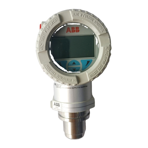
266CRx, 266JRx, 266CSx, 266JSx | OI/266CXX/266JXX/HART-EN Rev. B3
Contents
1ABB.................................................................................. 5
2Introduction ..................................................................... 5
2.1 About the manual ................................................ 5
2.2 Structure of the operating manual ........................ 5
2.3 Customer Service Centers worldwide .................. 5
3Safety............................................................................... 6
3.1 General information and notes for the reader........ 6
3.2 Intended use........................................................ 6
3.3 Improper use ....................................................... 6
3.4 Target groups and qualifications .......................... 6
3.5 Warranty provisions ............................................. 6
3.6 Plates and symbols.............................................. 7
3.6.1 Safety / warning symbols, note symbols .............. 7
3.7 Compliance with Pressure Equipment Directive
(2014/68/EU) ....................................................... 7
3.8 Transport............................................................. 7
3.9 Transport safety instructions ................................ 7
3.10 Obligations of the owner ...................................... 7
3.11 Storage conditions............................................... 8
3.12 Safety instructions for electrical installation........... 8
3.13 Safety instructions for operation........................... 8
3.14 Safety information for inspection and maintenance8
3.15 Returning devices ................................................ 8
3.16 Integrated management system........................... 8
3.17 Disposal .............................................................. 9
3.17.1Notice on WEEE Directive 2012/19/EU (Waste
Electrical and Electronic Equipment)..................... 9
3.17.2ROHS Directive 2011/65/EU................................ 9
4Unpacking the device ..................................................... 9
4.1 Scope of delivery ................................................. 9
4.2 Identification ........................................................ 9
4.3 Storage ............................................................... 9
4.4 Handling .............................................................. 9
5Product identification.................................................... 10
6Use in potentially explosive atmospheres ................... 11
6.1 Hazardous atmospheres.................................... 11
7Function and system design......................................... 12
7.1 Components of the pressure transmitter ............ 12
7.2 Product description ........................................... 12
7.3 Measuring range limits and span limits ............... 12
8Mounting........................................................................ 13
8.1 IP rating ............................................................. 13
8.2 Factory settings ................................................. 13
8.3 Venting / draining transmitters without diaphragm
seals.................................................................. 14
8.4 Mounting position .............................................. 14
8.5 Mounting dimensions 266CRx/JRx .................... 15
8.5.1 Transmitter with barrel housing .......................... 15
8.5.2 Transmitter with barrel housing and mounting
bracket, for vertical or horizontal mounting on
60 mm (2 in.) pipe.............................................. 16
8.5.3 Transmitter with DIN housing and mounting
bracket, for vertical or horizontal mounting on
60 mm (2 in.) pipe.............................................. 17
8.5.4 Transmitter with barrel housing and flat bracket, for
vertical or horizontal mounting on
60 mm (2 in.) pipe.............................................. 18
8.6 Montageabmessungen 266CSx/JSx.................. 19
8.6.1 Transmitter with barrel housing - Horizontal
flanges............................................................... 19
8.6.2 Transmitter with barrel housing - Vertical flanges 20
8.6.3 Transmitter with mounting bracket, for vertical or
horizontal mounting on 60 mm (2 in.) pipe pipe .. 21
8.6.4 Transmitter with DIN aluminum housing - horizontal
flanges with mounting bracket for vertical or
horizontal mounting on 60 mm (2 in.) pipe.......... 22
8.6.5 Transmitter with flat bracket, for vertical or
horizontal mounting on 60 mm (2 in.) pipe.......... 23
8.6.6 Installation via (optional) mounting brackets........ 24
8.7 Rotating the transmitter housing ........................ 24
8.8 Rotating the integral LCD display ....................... 25
8.9 Connecting impulse lines ................................... 25
8.10 Process connections ......................................... 26
8.11 Temperature measurement................................ 26
8.12 Mounting recommendations .............................. 26
8.12.1 Flow measurement of steam (condensible vapor) or
clean liquids....................................................... 27
8.12.2Flow measurement of gas or liquid with solids in
suspension ........................................................ 27
8.12.3Fill level measurement on closed tanks............... 28
8.12.4Fill level measurement on open tanks with fluids. 29
8.12.5Fill level measurement on the steam boiler (drum
water level)......................................................... 29
9Electrical connections................................................... 30
9.1 Cable connections ............................................. 30
9.2 Connection of the analog output (HART) ............ 31
9.3 Digital output (pulse / limit output) ...................... 32
9.4 Wiring ................................................................ 32
9.5 Protective conductor connection / grounding..... 32


