manuals.online logo
Brands
  1. Home
  2. •
  3. Brands
  4. •
  5. M-LOCKS
  6. •
  7. Lock
  8. •
  9. M-LOCKS ML6740 User manual

M-LOCKS ML6740 User manual

Mechanical Combination Lock
M-LOCKS BV Tel: +31 (0)314 376 876
Vlijtstraat 40 ver. 1.2 2017 12 11 Fax: +31 (0)314 376 878
NL-7005 BN Doetinchem 1 www.m-locks.com
Technical Manual
Mounting Instructions
ML6740
The VdS recognition of this lock is based on this
mounting instruction. Read carefully.
The force applied to the lock bolt should not exceed 1 KN. If higher force is applied, please consult
with the testing institute (i.e. UL, VdS). Only use supplied screws to mount the lock. Fix the lock
handtied.
The lock has to be fitted exclusively on steel secure storage. The mounting base also must be made of
steel . Installation on other materials only after consultation M - LOCKS or VdS .
It is recommended to prevent access to unauthorized persons to safety-relevant parts of the high-
security lock when the safe is open . Par example by a with a screws fixed interior cover.
The lock housing must be protected against destructive attacks from outside with suitable protective
materials .
CHARACTERISTICS
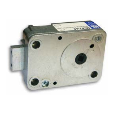
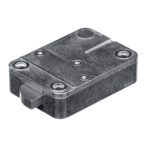
The ML 6740 is a manipulation proof 3-wheel combination lock with new features making it very easy
to mount. VdS Kl.2, EN1300 Class B, ECB-S, CNPP, IMP, DNV.
The lock has the standard foot print (66,7x41mm) and can be mounted in all four mounting-directions.
(HR, HL, VU, VD)
Measurements: 85mm x 61mm, x 29mm. Lock bolt: 25mm x 8mm with two M4 holes in the bolt head.
Bolt Travel: 8mm.
The lock has been tested with 10,000 opening cycles with a bolt load of 2.5 N (mounting position Bolt
right). All other mounting positions as well as higher loads (for example due to bolt work or blocking
element) must be tested by the safe manufacturer with at least 10,000 opening cycles and a
corresponding load.
The lock needs no spline key. It works with a square 6x6mm shaft as the spindle.
Two optional locking bars can be inserted to make a 3-way locking system.
Mechanical Dials
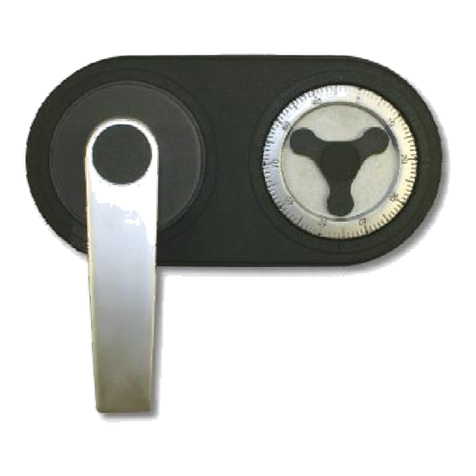
This mechanical lock compatible with the following M-LOCKS dials:
For more information, please read the technical description and mounting instruction of the dial and
ring assembly.
Due to the square shaft the lock is not compatible with dials that have a round, threaded spindle.
CS-serie
MD-serie
ST-serie
KL1060
KL1560
Mechanical Combination Lock
M-LOCKS BV Tel: +31 (0)314 376 876
Vlijtstraat 40 ver. 1.2 2017 12 11 Fax: +31 (0)314 376 878
NL-7005 BN Doetinchem 2 www.m-locks.com
DIMENSIONS / MOUNTING INSTRUCTIONS
The Lock is delivered with the Bolt retracted and
ready for mounting. Do not move the cam (part
with square hole) or the bolt. During installation
the bolt must stay in retracted position and
the cam lined up as shown left.
Only use the delivered 3 mounting screws (3x M6 with US ¼” available on demand) and fasten
handtight. (Torque approximately 3,5 Nm). With the lock in OPEN-position (bolt retracted) hold the
dial in a way that approximately “93” is under the opening index and push it with some pressure into
the lock. The shaft cannot be pulled out.
Mechanical Combination Lock
M-LOCKS BV Tel: +31 (0)314 376 876
Vlijtstraat 40 ver. 1.2 2017 12 11 Fax: +31 (0)314 376 878
NL-7005 BN Doetinchem 3 www.m-locks.com
Turn Dial LEFT to extend the bolt. The bolt must slide easily to the
end position and should not be restricted by the bolt work
Delivered Factory Code is: 4xL to 50.
4x Turn LEFT and pass “50” three times
and stop exactly on “50” under the opening
index the fourth time.
Due to installation tolerances it is possible that the code may have shifted up to two numbers
up or down. This shifting is normal and will be eliminated once the code is re-set. If the lock
does not open on “50”, try to open at „48“ then “49”, “51” or ”52”.
Also due to these tolerances it is important to re-set the code after installation.
With door open, move the bolt work and lock to locked position.
Dial the code at which the lock opened on the CHANGING INDEX.
Example: If the lock opens at “49.
4 x LEFT until “49” stops exactly at the Changing Index
1. Carefully insert change key on the inside of the safe door.
Slightly wiggle if necessary.
2. Turn change key as shown clockwise to the stop (approx. 90 deg.)
Never apply excessive force
If change key cannot be inserted or turned, the correct code has not been dialed to
the Changing Index on the dial. Take out the key and dial the valid code again.
Now dial your factory code using the CHANGING INDEX.
* We suggest you set the code to 10-20-30 as that matches the end-user instruction M-LOCKS
provides.
The last number must be higher than 20. Each number has to be at least 4 increments apart from
the others. For example: 49-45-41 and not 51-52-53.
Change Keys
If installers use the
same change key to
set up several locks,
it is important to
inspect the change
key regular basis.
If the change key is
bend or shows signs
of wear it needs to
be replaced.
Otherwise the new
code will not be set
exactly as dialed.
Mechanical Combination Lock
M-LOCKS BV Tel: +31 (0)314 376 876
Vlijtstraat 40 ver. 1.2 2017 12 11 Fax: +31 (0)314 376 878
NL-7005 BN Doetinchem 4 www.m-locks.com
4 x Turn LEFT, pass first code number three times and stop exactly on the number on
the Changing Index the fourth time.
3 x Turn RIGHT, pass second code number twice and stop exactly on the number on
the Changing Index the third time.
2 x Turn LEFT, pass third code number once and stop exactly on the number on the
Changing Index the second time and stop.
After the new Code is completely entered, turn change key LEFT and remove it. The new Code is
installed.
When turning the dial, if a number is passed, start over at the beginning.
Try the new code several times (using Opening Index) before closing the door!
DATA SHEET
Mechanics
Opening
manually
Locking
manually
Blocking element
3 Wheels
Mounting dimensions
standard
Certifications
VdS
Class 2
EN1300, ECB-S, CNPP,
A2P
Class B
UL
Group 2M
DNV
158-2 Listed
IMP
Klasa B
What if …
…accidentally the cam got moved before installation?
As long as the code has not been changed with the change key, the lock can be prepared for
mounting following the steps below:
1. Hold the lock so that you look at the cover and the bolt is to the right.
2. Turn the cam clockwise minimum 4 complete turns and stop when the cam is lined up as
shown in figure 1.
3. Turn cam counterclockwise until lock opens. The cam should be lined up with the “LOCK
OPEN” line on the cover (see figure 2).
…the dial is hard to turn or the dial is rubbing on the dial plate?
Loosen the screw that holds the shaft in the dial and pull out the dial slightly. Then tighten the screw
hand tight. Do not over tighten as that will pull the dial back in. Use liquid thread-lock like Loctite™ if
required.
4x
figure 1
figure 2
Mechanical Combination Lock
M-LOCKS BV Tel: +31 (0)314 376 876
Vlijtstraat 40 ver. 1.22017 12 11 Fax: +31 (0)314 376 878
NL-7005 BN Doetinchem 1 www.m-locks.com
Technical manual
Mounting instructions
ML6785
The VdS recognition of this lock is based on this mounting instruction. Read carefully.
The force applied to the lock bolt should not exceed 1 KN. If higher force is applied, please consult
with the testing institute (i.e. UL, VdS). Only use supplied screws to mount the lock. Fix the lock
handtied.
The lock has to be fitted exclusively on steel secure storage. The mounting base also must be made
of steel . Installation on other materials only after consultation M - LOCKS or VdS .
It is recommended to prevent access to unauthorized persons to safety-relevant parts of the high-
security lock when the safe is open . Par example by a with a screws fixed interior cover.
The lock housing must be protected against destructive attacks from outside with suitable protective
materials .
CHARACTERISTICS
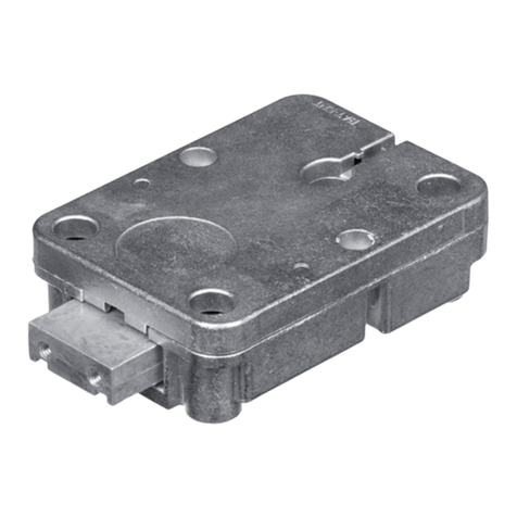
The ML6785 is a manipulation proof 3-wheel combination lock, VdS Kl. 2, EN1300 Cl. B certified, and
very easy to mount.
The lock has the standard foot print (66,5 x 41mm) and can be mounted in all four mounting-
directions. (RH, LH, VU, VD)
Measurements: 85mm x 61mm, x 29mm. Lock bolt: 25mm x 8mm with two M4 holes in the bolt. Bolt
travel: 8mm.
The lock has been tested with 10,000 opening cycles with a bolt load of 2.5 N (mounting position Bolt
right). All other mounting positions as well as higher loads (for example due to bolt work or blocking
element) must be tested by the safe manufacturer with at least 10,000 opening cycles and a
corresponding load.
Two optional locking bars (ML6790) can be inserted to make a 3-way locking system.
DIMENSIONS / MOUNTING INSTRUCTIONS
Mechanical Combination Lock
M-LOCKS BV Tel: +31 (0)314 376 876
Vlijtstraat 40 ver. 1.22017 12 11 Fax: +31 (0)314 376 878
NL-7005 BN Doetinchem 2 www.m-locks.com
1. Lock assembly
The lock can be installed in all 4-installation directions. The combination lock has a standard
footprint of 66.5 x 41mm. Only use supplied screws to mount the lock. Tighten the screws securely
so the lock body is attached firmly to the mounting surface. Fix hand tied (Maximum Torque 5, 5
Nm).
The bolt work must block the bolt sufficiently on both sides in slide-out position. (8mm) But if one
side is blocked a support must be fixed on the opposite side. The margin between closing point
and respectively support and bolt is 0.5-1mm. The support is not necessarily if the side pressure is
limited to 1.8kN. The bolt counter-pressure maximum 1kN.
2. Assembly of the dial:
Spindle has US-screw-thread 5/16-40 UNS-2A (spindle groove on "44"). Assemble the
ring so that the opening symbol is perpendicular above. Cut spindle to length so that the
spindle-end levels with the cam. Don’t let spindle stick out. Twist dial hand tight in the
cam and reverse approximately rotation until the correct spline key position. Spelling
ca.0,5mm axial.
The spindle transit through the armouring can have a maximum diameter of 10-12mm.
3. Spline key position
Depending upon installation of the lock there are 4 spline key positions possible, which are
indicated on the cam:
RH, LH, VU, VD.
Seen from the assembly side:
RH LH VD VU
The correct spline key position is very important, because otherwise the "prohibited area" (last
figure not between 0-20) moves in the operational range and can lead to lock malfunctions.
4. Place the spline key
If the spindle groove is on the correct spline key position drive the attached spline key
carefully in, so that the nose lies gently on the spindle.
5.
Turn dial LEFT to extend the bolt. The bolt must slide easily to the
end position and should not be restricted by the bolt work.
Mechanical Combination Lock
M-LOCKS BV Tel: +31 (0)314 376 876
Vlijtstraat 40 ver. 1.22017 12 11 Fax: +31 (0)314 376 878
NL-7005 BN Doetinchem 3 www.m-locks.com
Delivered Factory Code is: 4xL to 50.
4x Turn LEFT and pass “50” three times and stop exactly
on “50” under the opening index the fourth time.
Due to installation tolerances it is possible that the code may have shifted up to two
numbers up or down.
Also due to these tolerances it is important to re-set the code after installation.
With door open, turn the bolt work and lock to locked position.
Dial the code at which the lock opened, on the CHANGING INDEX.
Example: If the lock opens at “49.
4 x LEFT until “49” stops exactly at the Changing Index
1. Carefully insert change key on the inside of the safe door.
(Slightly wiggle if necessary.)
2. Turn change key as shown clockwise to the stop (approx. 90 deg.)
Never apply excessive force
If change key cannot be inserted or turned, the correct code has not been dialed to the
Changing Index on the dial. Take out the key and dial the valid code again
Now dial your new code using the CHANGING INDEX, f.e. 10-20-30.
(see user instructions of the lock) (The last number may not be between 0 and 20)
4 x Turn LEFT, pass first code number “10” three times and stop exactly on the
number on the Changing Index the fourth time.
3 x Turn RIGHT, pass second code number “20” twice and stop exactly on the
number on the Changing Index the third time.
2 x Turn LEFT, pass third code number “30” once and stop exactly on the number on
the Changing Index the second time.
When turning the dial, if a number is passed, start over at the beginning.
After the new code is completely entered, turn change key LEFT and remove it. The new code is
installed.
Try the new code several times (using Opening Index) before closing the door!
Change Keys
If installers use the
same change key to
set up several locks, it
is important to inspect
the change key regular
basis.
If the change key is
bend or shows signs of
wear it needs to be
replaced. Otherwise
the new code will not
be set exactly as
dialed.
Mechanical Combination Lock
M-LOCKS BV Tel: +31 (0)314 376 876
Vlijtstraat 40 ver. 1.22017 12 11 Fax: +31 (0)314 376 878
NL-7005 BN Doetinchem 4 www.m-locks.com
DATA
Mechanical
Opening
manually
Locking
manually
Blocking element
3 wheels
Manipulation-proof
Yes
Mounting dimensions
Standard
Certification
VdS
Klasse 2
EN 1300
Class B
ECB-S, CNPP, A2P
Class B
What if …
…accidentally the cam got moved before installation?
As long as the code has not been changed with the change key, the lock can be prepared for
mounting following the steps below:
1. Hold the lock so that you look at the cover and the bolt is to the right.
2. Turn the cam clockwise minimum 4 complete turns and stop when the cam is lined up as
shown in figure 1.
•Turn cam counterclockwise until lock opens. The cam should be lined up with the “LOCK
OPEN” line on the cover (see figure 2).
figure 2
figure 1

Other M-LOCKS Lock manuals

M-LOCKS Euroline EC10-40 User manual

M-LOCKS

M-LOCKS Euroline EC10-40 User manual

M-LOCKS DirectXion EM2010 DX User manual

M-LOCKS

M-LOCKS DirectXion EM2010 DX User manual

M-LOCKS ML6740 User manual

M-LOCKS

M-LOCKS ML6740 User manual

M-LOCKS EuroLine Modular Series User manual

M-LOCKS

M-LOCKS EuroLine Modular Series User manual

M-LOCKS EuroLine MODULAR Series User manual

M-LOCKS

M-LOCKS EuroLine MODULAR Series User manual

M-LOCKS RotoBolt User manual

M-LOCKS

M-LOCKS RotoBolt User manual

M-LOCKS Tantum Basic User manual

M-LOCKS

M-LOCKS Tantum Basic User manual

M-LOCKS EC1070 EuroLine series User manual

M-LOCKS

M-LOCKS EC1070 EuroLine series User manual

M-LOCKS EuroLine Modular Series User manual

M-LOCKS

M-LOCKS EuroLine Modular Series User manual

M-LOCKS E-Pass User manual

M-LOCKS

M-LOCKS E-Pass User manual

M-LOCKS EP 8050 HU User manual

M-LOCKS

M-LOCKS EP 8050 HU User manual

M-LOCKS EM3020 User manual

M-LOCKS

M-LOCKS EM3020 User manual
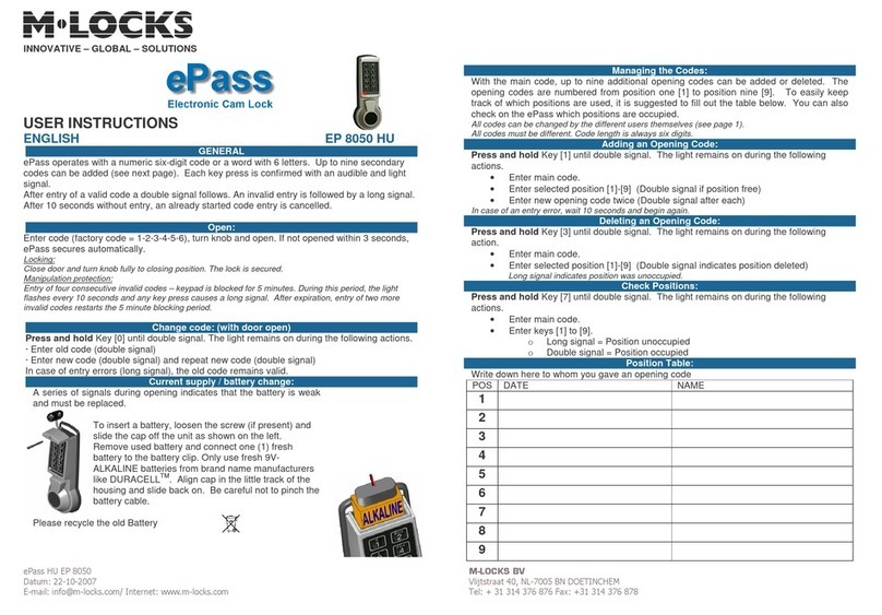
M-LOCKS Basic line Series User manual

M-LOCKS

M-LOCKS Basic line Series User manual

M-LOCKS Straightbolt EM3520 User manual

M-LOCKS

M-LOCKS Straightbolt EM3520 User manual

M-LOCKS Rotobolt EM2050 User manual

M-LOCKS

M-LOCKS Rotobolt EM2050 User manual

M-LOCKS EuroLine Compact series User manual

M-LOCKS

M-LOCKS EuroLine Compact series User manual

M-LOCKS T6530 User manual

M-LOCKS

M-LOCKS T6530 User manual
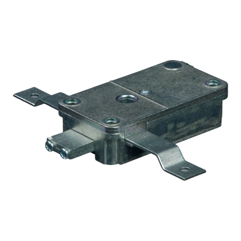
M-LOCKS EM1620 User manual

M-LOCKS

M-LOCKS EM1620 User manual
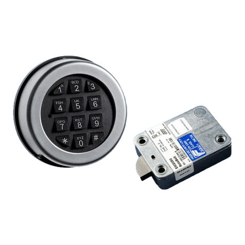
M-LOCKS Rotobolt EM2050 User manual

M-LOCKS

M-LOCKS Rotobolt EM2050 User manual

M-LOCKS E-Pass EP8050HL User manual

M-LOCKS

M-LOCKS E-Pass EP8050HL User manual

M-LOCKS EM1620 User manual

M-LOCKS

M-LOCKS EM1620 User manual

M-LOCKS E-Pass User manual

M-LOCKS

M-LOCKS E-Pass User manual
Popular Lock manuals by other brands

Ross 1000-SERIES operating instructions

Ross

Ross 1000-SERIES operating instructions

Salto Node installation guide

Salto

Salto Node installation guide

Schlage L-SERIES Brochure & specs

Schlage

Schlage L-SERIES Brochure & specs

KAWAJUN AC-827 quick start guide

KAWAJUN

KAWAJUN AC-827 quick start guide

schmersal AZM300Z-I2-ST-1P2P-N-DU Operation and assembly instructions

schmersal

schmersal AZM300Z-I2-ST-1P2P-N-DU Operation and assembly instructions

COMPX Timberline D270CB instruction sheet

COMPX

COMPX Timberline D270CB instruction sheet

Rockwell Automation 194R-P Series manual

Rockwell Automation

Rockwell Automation 194R-P Series manual

LEHMANN DIAL LOCK 60 operating instructions

LEHMANN

LEHMANN DIAL LOCK 60 operating instructions

Schlage 390G+ installation instructions

Schlage

Schlage 390G+ installation instructions

Securam ProLogic B01 operating instructions

Securam

Securam ProLogic B01 operating instructions

SECO-LARM E-941S-600DPSQ Series installation manual

SECO-LARM

SECO-LARM E-941S-600DPSQ Series installation manual

Wittkopp Primor 2600 Installer manual

Wittkopp

Wittkopp Primor 2600 Installer manual

Visionis VIS-ML1200LED-WH Installation & user guide

Visionis

Visionis VIS-ML1200LED-WH Installation & user guide

Schlage AD-200 installation instructions

Schlage

Schlage AD-200 installation instructions

Schlage L460 Service manual

Schlage

Schlage L460 Service manual

Simons Voss Technologies LockNode SREL2.G2 quick guide

Simons Voss Technologies

Simons Voss Technologies LockNode SREL2.G2 quick guide

D&D Technologies Lokk-Latch Deluxe installation instructions

D&D Technologies

D&D Technologies Lokk-Latch Deluxe installation instructions

CODELOCKS KL1050 Programming &  operating manual

CODELOCKS

CODELOCKS KL1050 Programming & operating manual

manuals.online logo
manuals.online logoBrands
  • About & Mission
  • Contact us
  • Privacy Policy
  • Terms and Conditions

Copyright 2025 Manuals.Online. All Rights Reserved.