AC Schnitzer X3 M-Technik User manual

1
-
-M
Mo
on
nt
ta
ag
ge
ea
an
nl
le
ei
it
tu
un
ng
g-
-
F
Fr
ro
on
nt
ts
sp
po
oi
il
le
er
r
E
El
le
em
me
en
nt
te
e
–
–
X
X3
3
(
(G
G0
01
1)
)
/
/
X
X4
4
(
(G
G0
02
2)
)–
–
M
M-
-T
Te
ec
ch
hn
ni
ik
k
T
Te
ei
il
le
e-
-N
Nr
r.
.:
:
5
51
11
11
1
3
30
01
1
3
31
10
0
(
(e
en
ng
gl
li
is
sh
h
v
ve
er
rs
si
io
on
n
s
se
ee
e
p
pa
ag
ge
e
1
11
1)
)

2
Allgemeine Hinweise !
AC Schnitzer Frontspoiler Elemente X3 (G01) –X4 (G02) M-Technik
Wichtige Hinweise !
Diese Montageanleitung ist unbedingt vor Beginn der Einbauarbeiten zu lesen. AC Schnitzer übernimmt keinerlei
Haftung für Schäden, die durch unsachgemässen Einbau entstehen !
Diese Montageanleitung ist zum Gebrauch durch autorisierte AC Schnitzer Händler bestimmt.
Zielgruppe dieser Montageanleitung ist in jedem Falle an BMW Fahrzeugen ausgebildetes Fachpersonal mit entspre-
chenden Fachkenntnissen.
Alle Abbildungen zeigen LHD Fahrzeuge, bei RHD Fahrzeugen ist sinngemäß oder nach gesonderten Montagehin-
weisen vorzugehen.
Montage
Alle Arbeiten sind unter Berücksichtigung der geltenden Sicherheitsvorschriften durchzuführen (z.B. Schutzbrille).
Bauteile und Flächen die miteinander verklebt werden, müssen grundsätzlich mit Reiniger gesäubert werden !
Trocknungszeit des Klebers ca. 24 Stunden. Waschanlagenfest nach ca. 48 Stunden.
AC Schnitzer Frontspoiler Elementenur in Verbindung mit……….
... Fahrzeuge mit M-Technik Aerodynamik
Lackieren
Vor dem Lackieren, müssen alle AC Schnitzer Karosserie Komponenten am Fahrzeug auf Passgenauigkeit (z.B.
Anlageflächen /-konturen) überprüft werden.
Mögliche Nacharbeiten (z.B. Anlageflächen /-konturen nachschleifen) sollten vor dem Lackieren erfolgen !
Lackieranleitung und entsprechende Hinweise wie Lackierempfehlungen sind als Anhang am Ende der Montagean-
leitung zu finden (siehe Inhaltsverzeichnis).
Lackiervorschriften des Lackherstellers unbedingt beachten !
Einbauzeit (1 AW = 5 Minuten)
Die Einbauzeit beträgt 12 AW, die je nach Zustand und Ausstattung des Fahrzeugs abweichen kann.
Lackierzeit (1 AW = 5 Minuten)
Die Lackierzeit beträgt 18 AW, die je nach Beschaffenheit des Bauteils abweichen kann.
Montageanleitung Nr.: 5111 301 310 / Stand: 31.08.2018 / TSch / REV01
AC Schnitzer - automobile Technik - Neuenhofstraße 160 - D - 52078 Aachen - Tel. 0241/5688 -130 Fax -135

3
Gelieferte Bauteile
AC Schnitzer Frontspoiler Elemente X3 (G01) –X4 (G02) M-Technik
A AC Schnitzer Frontspoiler Element –rechts –5111 301 310R
AC Schnitzer Frontspoiler Element –links –5111 301 310L
BAC Schnitzer Montagehilfe (Holzstäbchen)
CAC Schnitzer Vitro Aufkleber –schwarz –
DKlebepackung 80ml, inkl. Reiniger
ETÜV Gutachten
Montageanleitung Nr.: 5111 301 310 / Stand: 31.08.2018 / TSch / REV01
AC Schnitzer - automobile Technik - Neuenhofstraße 160 - D - 52078 Aachen - Tel. 0241/5688 -130 Fax -135
1x
1x
1x
1x
2x
1x

4
Montageanleitung
AC Schnitzer Frontspoiler Elemente X3 (G01) –X4 (G02) M-Technik
Montage der AC Schnitzer Frontspoiler Elemente
Bauteile und Flächen die miteinander verklebt wer-
den, müssen grundsätzlich mit dem mitgelieferten
Reiniger gesäubert werden !
Abb. 1
Klebenut (1) der Frontspoiler Elemente vor der Monta-
ge von Lack- und Grundierungsresten befreien.
Abb. 2
Klebenut der Frontspoiler Elemente anschleifen und
mit dem mitgelieferten Reiniger säubern.
AC Schnitzer Frontspoiler Elemente am Fahrzeug an-
halten und Position der AC Schnitzer Frontspoiler Ele-
mente prüfen.
Position der AC Schnitzer Frontspoiler Elemente ggf.
markieren.
Abb. 3
Mitgelieferten Kleber in Form einer Kleberaupe mit Ø
5mm am inneren Ende der Klebenut auftragen.
Montageanleitung Nr.: 5111 301 310 / Stand: 31.08.2018 / TSch / REV01
AC Schnitzer - automobile Technik - Neuenhofstraße 160 - D - 52078 Aachen - Tel. 0241/5688 -130 Fax -135
1

5
Montageanleitung
AC Schnitzer Frontspoiler Elemente X3 (G01) –X4 (G02) M-Technik
Montage ….
Abb. 4
AC Schnitzer Frontspoiler Element am Fahrzeug an-
setzen.
Beim Ansetzen des AC Schnitzer Frontspoiler Ele-
ments darauf achten…
Abb. 5
...AC Schnitzer Frontspoiler Element ca. 20mm unter-
halb der Frontschürzenkontur ansetzen.
Abb. 6
…dass die Kontur mit der Radlaufblende bündig ab-
schließt.
Montageanleitung Nr.: 5111 301 310 / Stand: 31.08.2018 / TSch / REV01
AC Schnitzer - automobile Technik - Neuenhofstraße 160 - D - 52078 Aachen - Tel. 0241/5688 -130 Fax -135

6
Montageanleitung
AC Schnitzer Frontspoiler Elemente X3 (G01) –X4 (G02) M-Technik
Montage ….
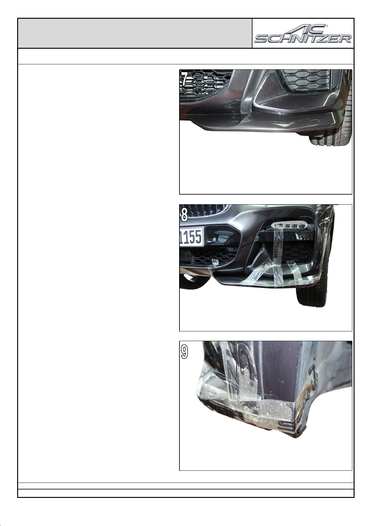
Abb. 7
…AC Schnitzer Frontspoiler Element sollte einen
gleichbleibenden Abstand zur Frontschürzenkontur
aufweisen.
Auf Seitengleichheit der AC Schnitzer Frontspoiler
Elemente achten.
Abb. 8 & 9
AC Schnitzer Frontspoiler Element mit Klebeband fixie-
ren.
Montageanleitung Nr.: 5111 301 310 / Stand: 31.08.2018 / TSch / REV01
AC Schnitzer - automobile Technik - Neuenhofstraße 160 - D - 52078 Aachen - Tel. 0241/5688 -130 Fax -135
7
Montageanleitung
AC Schnitzer Frontspoiler Elemente X3 (G01) –X4 (G02) M-Technik
Montage ….
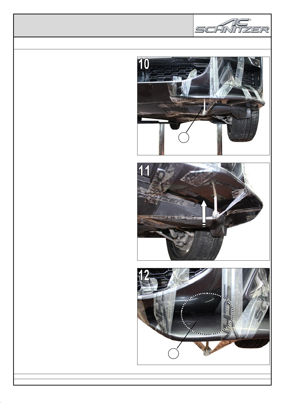
Abb. 10 bis 12
AC Schnitzer Montagehilfe (1) (Holzstäbchen) von un-
ten, durch die vorhanden Bohrungen des AC Schnitzer
Frontspoiler Elements führen und mit Klebeband so
fixieren, dass die Montagehilfe das AC Schnitzer
Frontspoiler Element im Konturenbereich (2) (siehe
Abb.12) leicht anhebt und die Kontur anliegt.
Nicht zu fest spannen !
Montageanleitung Nr.: 5111 301 310 / Stand: 31.08.2018 / TSch / REV01
AC Schnitzer - automobile Technik - Neuenhofstraße 160 - D - 52078 Aachen - Tel. 0241/5688 -130 Fax -135
1
2
8
Montageanleitung
AC Schnitzer Frontspoiler Elemente X3 (G01) –X4 (G02) M-Technik
Montage ….
Evtl. an den Klebeflächen austretenden Kleber mit dem
mitgelieferten Reiniger entfernen.
Trocknungszeit des Klebers ca. 24 Stunden.
Waschanlagenfest nach ca. 48 Stunden.
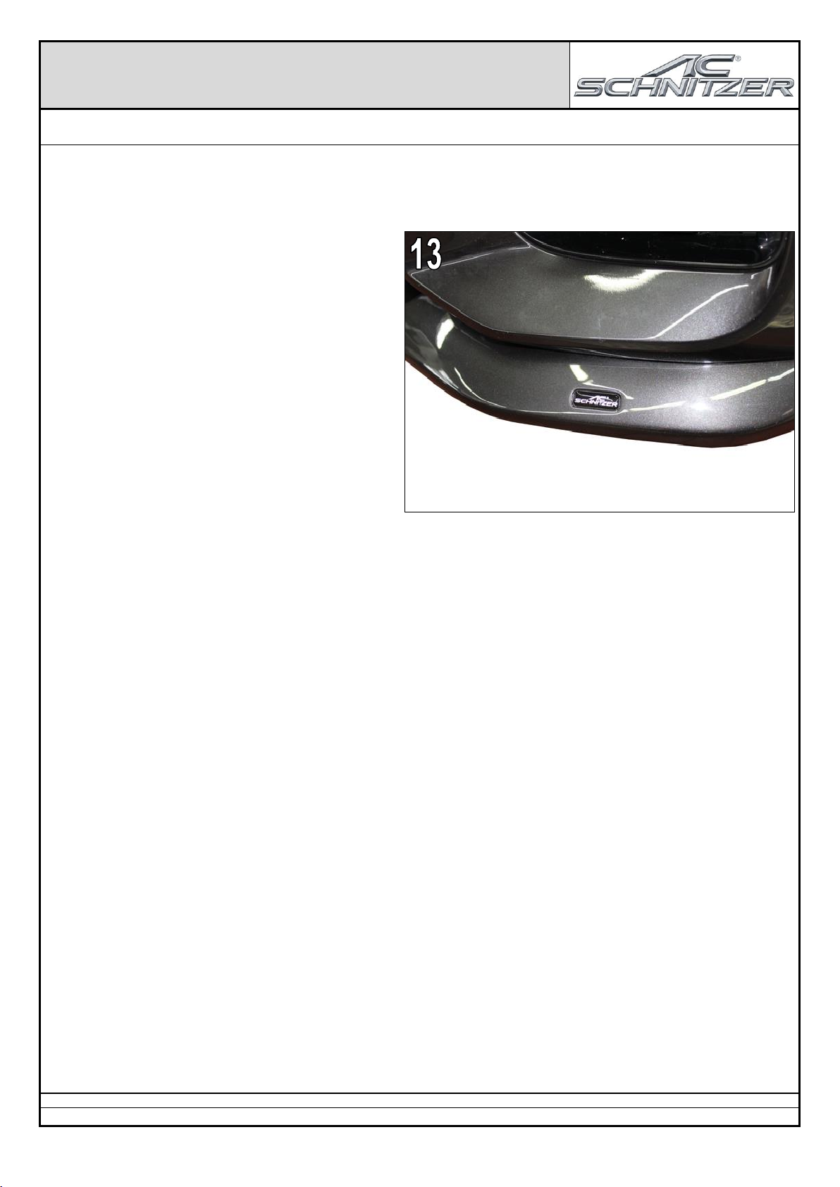
Abb. 13
Mitgelieferten AC Schnitzer Vitro Aufkleber in die dafür
vorgesehene Aussparung am linken AC Schnitzer
Frontspoiler Element einkleben.
Irrtum und Änderung sowie
technische Weiterentwicklungen vorbehalten !
Montageanleitung Nr.: 5111 301 310 / Stand: 31.08.2018 / TSch / REV01
AC Schnitzer - automobile Technik - Neuenhofstraße 160 - D - 52078 Aachen - Tel. 0241/5688 -130 Fax -135
9
Lackieranleitung
Hinweise zum Lackieren von AC Schnitzer Bauteilen
Vor dem Lackieren, müssen alle AC Schnitzer Karosserie Komponenten am Fahrzeug auf Passgenauigkeit (z.B. Anlageflä-
chen /-konturen) überprüft werden.
Mögliche Nacharbeiten (z.B. Anlagefläche /-konturen nachschleifen) sollten vor dem Lackieren erfolgen !
Die Qualität und Haltbarkeit der Lackierung eines Bauteils ist von der Vorbehandlung und von äußeren Einflüssen abhängig
und damit mit keinem anderen Karosserieteil vergleichbar.
Um Verzug / Verformung bei der Bearbeitung und beim Trocknen zu vermeiden sind AC Schnitzer Bauteile auf einer ent-
sprechenden Vorrichtung zu platzieren.
Hinweis !
Bitte beachten Sie unbedingt die Lackiervorschriften des Lackherstellers !
Lackierschritte:
1. Reinigen: Kunststoffreiniger / Silikonentferner
2. Tempern: 30Min. bei max. 40° Celsius Objekttemperatur
3. Prüfen: Kanten und Nähte der Oberfläche (evtl. Poren), ggf. schleifen
4. Schleifen: 2K Spachtel P220 –P280 (trocken), komplettes Bauteil P400 –P600 (trocken)
5. Abkleben: Klebeflächen, TÜV-Kennzeichnung, Typschilder
6. Reinigen: Silikonentferner
7. Füllern: 2K HS-Füller
8. Trocknen: 1Std. bei max. 40° Celsius Objekttemperatur, Bauteil sollte über Nacht in der
Trockenkammer verbleiben
9. Entfernen: Abklebung Typenschilder, Klebeflächen und TÜV-Kennzeichnung
10. Schleifen: P800 (trocken)
11. Reinigen: Silikonentferner
12. Abkleben: Klebeflächen
13. Lackieren: Technische Daten und Lackierhinweise des Lackherstellers beachten
14. Trocknen: 1Std. bei max. 40° Celsius Objekttemperatur, Bauteil sollte über Nacht in der
Trockenkammer verbleiben
Lackieranleitung Stand: 01/2010
AC Schnitzer - automobile Technik - Neuenhofstraße 160 - 52078 Aachen - Tel. 0241/5688 -130 Fax -135

10
… weitere AC Schnitzer Produkte
AC Schnitzer Leistungssteigerung

11
-
-F
Fi
it
tt
ti
in
ng
g
I
In
ns
st
tr
ru
uc
ct
ti
io
on
ns
s-
-
F
Fr
ro
on
nt
t
S
Sp
po
oi
il
le
er
r
E
El
le
em
me
en
nt
ts
s
–
–
X
X3
3
(
(G
G0
01
1)
)
/
/
X
X4
4
(
(G
G0
02
2)
)–
–
M
M-
-T
Te
ec
ch
hn
ni
ik
k
P
Pa
ar
rt
t
N
No
o.
.:
:
5
51
11
11
1
3
30
01
1
3
31
10
0

12
General Notes !
AC Schnitzer Front Spoiler Elements X3 (G01) –X4 (G02) M-Technik
Important Notes !
These Fitting Instructions must be read in full before beginning installation work. AC Schnitzer bears no liability for
damage caused by incorrect installation !
These Fitting Instructions are intended solely for use by authorised AC Schnitzer dealers.
These Fitting Instructions are in all cases directed at professionals trained in BMW vehicles who have the correspond-
ing specialist knowledge.
All diagrams show LHD vehicles, for RHD vehicles proceed accordingly or follow separate Fitting Instructions.
As manufacturer, we are obliged to point out that any changes you make to a vehicle licensed for use on public roads
require approval by a test centre and registration in the vehicle documents.
As the legal regulations may vary according to location, please contact the competent authorities for information.
Fitting
Carry out all work in accordance with applicable safety regulations (e.g. wear safety goggles).
Components and surfaces to be glued together must first be thoroughly cleaned with cleaner.
The adhesive drying time is 24 hours. The vehicle can be washed in a car wash after approx. 48 hours.
AC Schnitzer Front Spoiler Elementsonly be fitted to……….
... Vehicles with M-Technik bodykit
Painting
Before painting, all AC Schnitzer bodystyling components must be checked for fit on the vehicle (e.g. contact sur-
faces/contours).
Any retouching work (e.g. sanding of contact surfaces/contours) must be carried out before painting !
Painting Instructions and corresponding notes and recommendations are attached at the end of these Fitting Instruc-
tions (see Contents).
The instructions of the paint manufacturer must be observed !!
Fitting Time (1 unit = 5 minutes)
The fitting time is 12 units, which may vary depending on vehicle condition and equipment level.
Painting Time (1 unit = 5 minutes)
The painting time is 18 units, which may vary depending on component composition.
Fitting Instructions No.: 5111 301 310 / Issue: 31.08.2018 / TSch / REV01
AC Schnitzer - automobile Technik - Neuenhofstraße 160 - D - 52078 Aachen - Tel. 0241/5688 -130 Fax -135

13
Components Supplied
AC Schnitzer Front Spoiler Elements X3 (G01) –X4 (G02) M-Technik
A AC Schnitzer Front Spoiler Elements –right –5111 301 310R
AC Schnitzer Front Spoiler Elements –left –5111 301 310L
B AC Schnitzer mounting aid (wood rod)
C AC Schnitzer sticker –black –
D Adhesive pack 80ml, inc. cleaner
E TÜV certificate
Fitting Instructions No.: 5111 301 310 / Issue: 31.08.2018 / TSch / REV01
AC Schnitzer - automobile Technik - Neuenhofstraße 160 - D - 52078 Aachen - Tel. 0241/5688 -130 Fax -135
1x
1x
1x
1x
2x
1x

14
Montageanleitung
AC Schnitzer Front Spoiler Elements X3 (G01) –X4 (G02) M-Technik
Fittint the AC Schnitzer Front Spoiler Elements
Components and surfaces to be glued together
must first be thoroughly cleaned with cleaner !
Fig. 1
Remove paint and primer residue from the AC
Schnitzer front spoiler elements adhesive groove (1).
Fig.2
Sand down the adhesive groove (Fig. 1.1) on the AC
Schnitzer front spoiler elements and using the cleaner
supplied.
Attach the AC Schnitzer front spoiler elements on the
vehicle and check the position of the AC Schnitzer front
spoiler elements.
Mark the position of the AC Schnitzer front spoiler ele-
ments if necessary.
Fig.3
Apply the adhesive supplied as a 5mm bead at the in-
ner end of the adhesive groove of the AC Schnitzer
front spoiler elements.
Fitting Instructions No.: 5111 301 310 / Issue: 31.08.2018 / TSch / REV01
AC Schnitzer - automobile Technik - Neuenhofstraße 160 - D - 52078 Aachen - Tel. 0241/5688 -130 Fax -135
1

15
Montageanleitung
AC Schnitzer Front Spoiler Elements X3 (G01) –X4 (G02) M-Technik
Fitting ….
Fig.4
Place the AC Schnitzer front spoiler element on the
vehicle.
When attaching the AC Schnitzer front spoiler element,
make sure that...
Fig. 5
.... Attach AC Schnitzer front spoiler element approx.
20mm below - halfway of the front skirt contour.
Fig.6
... that the contour is flush with the wheel cover plate.
Fitting Instructions No.: 5111 301 310 / Issue: 31.08.2018 / TSch / REV01
AC Schnitzer - automobile Technik - Neuenhofstraße 160 - D - 52078 Aachen - Tel. 0241/5688 -130 Fax -135
16
Montageanleitung
AC Schnitzer Front Spoiler Elements X3 (G01) –X4 (G02) M-Technik
Fitting ….
Fig.7
.... AC Schnitzer front spoiler element should have a
constant distance to the front skirt.
Pay attention to the equality of sides of the AC
Schnitzer front spoiler elements.
Fig. 8 & 9
Fix the AC Schnitzer front spoiler element with adhe-
sive tape.
Fitting Instructions No.: 5111 301 310 / Issue: 31.08.2018 / TSch / REV01
AC Schnitzer - automobile Technik - Neuenhofstraße 160 - D - 52078 Aachen - Tel. 0241/5688 -130 Fax -135

17
Montageanleitung
AC Schnitzer Front Spoiler Elements X3 (G01) –X4 (G02) M-Technik
Fitting ….
Fig. 10 until 12
From below, guide the mounting aid (1) (wooden rod)
through the existing holes and fix with adhesive tape so
that the mounting aid lifts the AC Schnitzer front spoiler
element in the contour region on the front skirt (2) (see
also Fig.12) contour lies neatly in place.
Do not over-tighten !
Fitting Instructions No.: 5111 301 310 / Issue: 31.08.2018 / TSch / REV01
AC Schnitzer - automobile Technik - Neuenhofstraße 160 - D - 52078 Aachen - Tel. 0241/5688 -130 Fax -135
1
2

18
Montageanleitung
AC Schnitzer Front Spoiler Elements X3 (G01) –X4 (G02) M-Technik
Fitting ….
Remove any surplus adhesive using the cleaner sup-
plied.
The adhesive drying time is 24 hours.
The vehicle can be washed in a car wash after
approx. 48 hours.
Fig. 13
Affix the AC Schnitzer sticker supplied in the recess
provided.
Subject to errors, modifications and technical refinements !
Fitting Instructions No.: 5111 301 310 / Issue: 31.08.2018 / TSch / REV01
AC Schnitzer - automobile Technik - Neuenhofstraße 160 - D - 52078 Aachen - Tel. 0241/5688 -130 Fax -135
19
Painting Instructions
Notes on Painting AC Schnitzer Components
Before painting, all AC Schnitzer bodystyling components must be checked for fit on the vehicle (e.g. contact surfac-
es/contours).
Anyretouching work (e.g. sanding of contact surfaces/contours) must be carried out before painting !
The quality and durabilityof the paint on a component depends on the preparation and external influences, and cannot
therefore be compared with that on any other bodyelement.
To avoid distortion/deformation during working and drying, AC Schnitzer components should be placed on a corresponding
jig.
Note !
The painting instructions of the paint manufacturer must be followed !
Painting Steps:
1. Cleaning: Plastic cleaner / Silicone remover
2. Tempering: 30 min. at max. 40° C object temperature
3. Inspection: Edges and seams on surface (pores etc.), sand down if necessary
4. Sanding: 2K stopper P220 –P280 (dry), complete component P400 –P600 (dry)
5. Masking off: Contact surfaces, TÜV marking, rating plates
6. Cleaning: Silicone remover
7. Filling: 2K HS filler
8. Drying: 1 hour at max. 40° C object temperature, component should remain in drying
cabinet overnight
9. Removal: Masking tape on rating plates, contact surfaces and TÜV marking
10. Sanding: P800 (dry)
11. Cleaning: Silicone remover
12. Masking off: Contact surfaces
13. Painting: Observe technical data and painting instructions from paint manufacturer
14. Drying: 1 hour at max. 40° C object temperature, component should remain in drying
cabinet overnight
Painting Instructions Issue: 01/2010
AC Schnitzer - automobile Technik - Neuenhofstraße 160 - 52078 Aachen - Tel. 0241/5688 -130 Fax -135

20
… further AC Schnitzer Produkte
AC Schnitzer efficient performance unit
This manual suits for next models
4
Table of contents
Languages:
Other AC Schnitzer Automobile Accessories manuals

AC Schnitzer
AC Schnitzer 5131 501 110 User manual

AC Schnitzer
AC Schnitzer 5131 239 110 User manual

AC Schnitzer
AC Schnitzer 6131 282 310 User manual

AC Schnitzer
AC Schnitzer 5111 282 540 User manual

AC Schnitzer
AC Schnitzer 5112 210 110 User manual

AC Schnitzer
AC Schnitzer G05 User manual

AC Schnitzer
AC Schnitzer LHD User manual

AC Schnitzer
AC Schnitzer F40 User manual


