manuals.online logo
Brands
  1. Home
  2. •
  3. Brands
  4. •
  5. aci
  6. •
  7. Accessories
  8. •
  9. aci A/SCTE-50 User manual

aci A/SCTE-50 User manual

Installation and Operation Instructions
Part # A/SCTE-50, A/SCTE-250,
A/SCTV-50, A/SCTV-250
2305 Pleasant View Rd. Middleton Industrial Park Middleton, WI 53562
PH: (608) 831-2585 FAX (608) 831-7407
File Name: I0000142 Rev 6 Doc.
Page 1 of 3
ACI
Automation Components, Inc.
Please Read Instructions Carefully Before Installation!
Safety
This product is not intended to be used for Life or Safety applications.
This product is not intended for use in any hazardous or classified locations.
Disconnect and lock out all power sources before installation as severe injury or death may result from electrical
shock due to contact with high voltage wires. 

Installation
Make sure that all installations are in compliance with all national and local electrical codes. Only qualified individuals that are
familiar with codes, standards, and proper safety procedures for high-voltage installations should attempt installation. The
current sensor will not require external power, since the power for the current sensor is induced from the conductor being
monitored.
The A/SCTE & A/SCTV Series Analog Current Sensors should be used on Insulated Conductors Only! The current sensors may
be mounted in any position using the (2) #8 x 3/4” Tek screws and the mounting holes in the base or snapped directly onto the
35mm DIN rail (See Figures 1 & 2 below). Leave a minimum distance of 1” (3 cm) between the current
sensor and any other magnetic devices such as contactors and transformers.
3X3X
L
IS
T
E
D
AutomationComponents,Inc.
IN
D.C
O
N
T.E
Q
.
Middleton,WI
C
3
JH
X
ACI
A/SCTE-50
U
S
L
IS
T
E
D
AutomationComponents,Inc.
IN
D
.C
O
N
T.E
Q
.
Middleton,WI
C
3J
H
X
ACI
A/SCTE-50
U
S
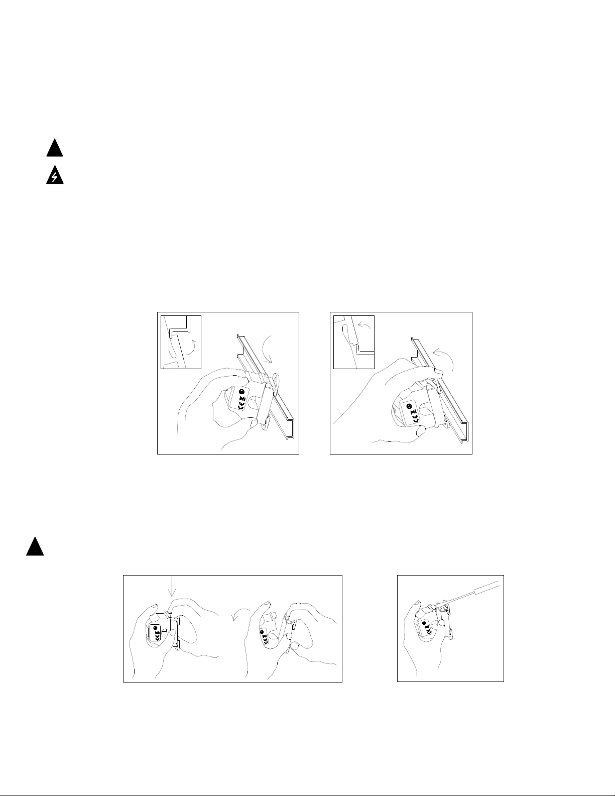
Figure 1: Sensor Placed on Rail Figure 2: Sensor Removed from Rail
Latch Operation:
Pressing down on the two (2) side tabs and swinging the cover open opens the split core current sensor as shown in Figure 3
below. Lifting up on the latch with a flat-tip screwdriver as shown in Figure 4 below can also open the unit. Press down firmly on
the cover to close the current sensor. An audible “click” will be heard as the tab slides over the tongue on the base.
Caution: Mating surfaces of the magnetic core are exposed when the sensor is open. Silicone grease, present on the cores to
prevent rust, may capture grit and dirt if care is not exercised. Operation can be impaired if anything prevents good
contact between pole pieces. Visually check the mating parts of the core before closing the current sensor.
3JH
X
U
S
L
IS
T
E
D
IN
D
.C
O
N
T.E
Q
.
C
A/SCTE-50
ACI
USC
Middleton,W I
Automation Components, Inc.
3JHX
IND.CONT.EQ.
LISTED
CU
S
L
IS
TE
D
IND
.CO
NT
.E
Q
.
3J
HX
AutomationComponents,Inc.
ACI
Middleton,WI
A/SCTE-50
Figure 3: Opening Sensor by Hand Figure 4: Opening w/ Screwdriver


!
!
2305 Pleasant View Rd. Middleton Industrial Park Middleton, WI 53562
PH: (608) 831-2585 FAX (608) 831-7407
File Name: I0000142 Rev 6 Doc.
Page 2 of 3
Wiring
ACI recommends the use of a 2 conductor 16 to 22 AWG shielded cable, copper wire only for all Analog current sensor
installations. A maximum wire length of 30 meters (98.4 feet) should be used between the A/SCTE and A/SCTV Series current
sensors and the Building Management System or controller. Note: When using a shielded cable, be sure to connect only (1) end
of the shield to ground at the controller. Connecting both ends of the shield to ground may cause a ground loop. When
removing the shield from the sensor end, make sure to properly trim the shield so as to prevent any chance of shorting. The current
sensors terminals are polarity sensitive and represent a linear 0 to 5 or 0 to 10 VDC output signal. The recommended torque to be
used on the terminal block connections is 0.67 Nm or 5.93 in-lbs. The aperture (hole) size of the current sensor is 0.75” (1.90 cm)
and will accept a maximum cable diameter of 350 MCM’s.

Operating Specifications
*Note: All current sensors are shipped from the factory with the jumper set in the high range.
Wiring Example
Power: These current sensors DO NOT
need an external power source,
since the power is self-induced
from the monitored load
or conductor.
Connections: Shielded, twisted pair cable is
recommended for these connections.
Note: Ground shield at control
system end only!
GND (Shield)
PLC, DDC, or Data
Acquisition System
(-) Signal Common
+ 0-5 or 0-10 VDC
+
_
Analog Input
Troubleshooting
Problem Solution
No reading - Verify that there is current flowing thru the conductor being monitored with a
clamp-on current probe. The power for the current sensor is induced from the
conductor being monitored.
- Check the polarity of the circuit.
- Verify that the terminals are screwed down, wires are firmly in place.
- Disconnect the wires from the current sensor output. Measure the voltage across
the current sensor output with a Voltmeter to verify that the sensor is working
properly.
Erratic readings - Verify that the wires are terminated properly.
- In areas of high RF interference, shielded cable may be necessary to stabilize
signal.
Inaccurate readings - If you suspect that the current sensor is not reading within the accuracy
specifications, please contact the factory for assistance.
ACI Model # Output Range Jumper * Max. Sensing
Current Voltage
Max. Continuous
Current
Max. Current for
6 seconds
A/SCTE-50 0 to 5 VDC
0-10 Amps
0-20 Amps
0-50 Amps
Low
Middle
High
600 VAC 100 Amps
150 Amps
200 Amps
125 Amps
225 Amps
300 Amps
A/SCTE-250 0 to 5 VDC
0-100 Amps
0-200 Amps
0-250 Amps
Low
Middle
High
600 VAC 200 Amps
360 Amps
400 Amps
250 Amps
450 Amps
500 Amps
A/SCTV-50 0 to 10 VDC
0-10 Amps
0-20 Amps
0-50 Amps
Low
Middle
High
600 VAC 60 Amps
100 Amps
160 Amps
80 Amps
200 Amps
300 Amps
A/SCTV-250 0 to 10 VDC
0-100 Amps
0-200 Amps
0-250 Amps
Low
Middle
High
600 VAC 160 Amps
320 Amps
400 Amps
200 Amps
400 Amps
500 Amps
2305 Pleasant View Rd. Middleton Industrial Park Middleton, WI 53562
PH: (608) 831-2585 FAX (608) 831-7407
File Name: I0000142 Rev 6 Doc.
Page 3 of 3
Current Conversion Formulas
To convert the current sensor output signal to a current reading.
0-10 Volt output to Current reading (0 Volts = 0 Amps and 10 Volts = 250 Amps for A/SCTV-250)
Example: 5 Volts current sensor output signal
Total Span = 250 Amps
Multiplier = 10V-0V/Total Span = .04
(5 Volts) / 0.04 = 125 Amps
WEEE Directive
At the end of their useful life the packaging and product should be disposed of via a suitable recycling centre. Do not dispose of
with household waste. Do not burn.
LISTED
C US
IND.CONT.EQ.
3JHX

This manual suits for next models

3

Other aci Accessories manuals

aci DRN3.1 User manual

aci

aci DRN3.1 User manual

aci ACCESS series Installation instructions

aci

aci ACCESS series Installation instructions

aci HAZARDOUS ROOM Series Installation instructions

aci

aci HAZARDOUS ROOM Series Installation instructions

aci Room Series Installation instructions

aci

aci Room Series Installation instructions

aci A/CTE2 Series Configuration guide

aci

aci A/CTE2 Series Configuration guide

aci A/CTE-50 User manual

aci

aci A/CTE-50 User manual

aci A/CTE-50 User manual

aci

aci A/CTE-50 User manual

aci DUCT Series User manual

aci

aci DUCT Series User manual

aci TUCH2 User manual

aci

aci TUCH2 User manual

aci OA2630A Service manual

aci

aci OA2630A Service manual

aci Room Series Installation instructions

aci

aci Room Series Installation instructions

aci BACnet / Modbus IMMERSION Series Installation instructions

aci

aci BACnet / Modbus IMMERSION Series Installation instructions

aci TUCH2 Installation instructions

aci

aci TUCH2 Installation instructions

aci HAZARDOUS ROOM Series Installation instructions

aci

aci HAZARDOUS ROOM Series Installation instructions

aci BACnet Outside Series Installation instructions

aci

aci BACnet Outside Series Installation instructions

aci TUCH2 User manual

aci

aci TUCH2 User manual

aci A/CTA2 Series Installation instructions

aci

aci A/CTA2 Series Installation instructions

aci ACCESS series Installation instructions

aci

aci ACCESS series Installation instructions

aci IMMERSION SERIES Installation instructions

aci

aci IMMERSION SERIES Installation instructions

aci A/CTA2-5 User manual

aci

aci A/CTA2-5 User manual

aci ROOM Series Installation instructions

aci

aci ROOM Series Installation instructions

aci A/SCTA Series Installation instructions

aci

aci A/SCTA Series Installation instructions

aci A/TT Remote Probe Series Installation instructions

aci

aci A/TT Remote Probe Series Installation instructions

aci DT2650 Installation instructions

aci

aci DT2650 Installation instructions

Popular Accessories manuals by other brands

TeraBee TeraRanger Multiflex Installation and operation manual

TeraBee

TeraBee TeraRanger Multiflex Installation and operation manual

Utilitech R1615D36 quick guide

Utilitech

Utilitech R1615D36 quick guide

Alpha Comm Enterprises POWER FUEL user manual

Alpha Comm Enterprises

Alpha Comm Enterprises POWER FUEL user manual

Burkert Type MS01 operating instructions

Burkert

Burkert Type MS01 operating instructions

i-gatU POD-30 user manual

i-gatU

i-gatU POD-30 user manual

SmartSun MEDIDA user manual

SmartSun

SmartSun MEDIDA user manual

Gastroback 41620 operating instructions

Gastroback

Gastroback 41620 operating instructions

Ace 3035466 (AC-6180) owner's manual

Ace

Ace 3035466 (AC-6180) owner's manual

Cornelius 000 PLUS installation manual

Cornelius

Cornelius 000 PLUS installation manual

Baumer OADM 20I2460/S14C quick start guide

Baumer

Baumer OADM 20I2460/S14C quick start guide

Dometic CFX3 25 Short Operating Manual

Dometic

Dometic CFX3 25 Short Operating Manual

Azbil CY8100C1001 instructions

Azbil

Azbil CY8100C1001 instructions

Allen-Bradley 1769-SM1 user manual

Allen-Bradley

Allen-Bradley 1769-SM1 user manual

Crow EDS-3000 Installation instructions and user guide

Crow

Crow EDS-3000 Installation instructions and user guide

PCB Piezotronics 105 Series Installation and operating manual

PCB Piezotronics

PCB Piezotronics 105 Series Installation and operating manual

STEINEL Control Pro IR Quattro MICRO DCS manual

STEINEL

STEINEL Control Pro IR Quattro MICRO DCS manual

JK Audio BlueDriver-M3 user guide

JK Audio

JK Audio BlueDriver-M3 user guide

Thermo Scientific 8000DH Series Operating and maintenance manual

Thermo Scientific

Thermo Scientific 8000DH Series Operating and maintenance manual

manuals.online logo
manuals.online logoBrands
  • About & Mission
  • Contact us
  • Privacy Policy
  • Terms and Conditions

Copyright 2025 Manuals.Online. All Rights Reserved.