manuals.online logo
Brands
  1. Home
  2. •
  3. Brands
  4. •
  5. Acrel
  6. •
  7. Measuring Instrument
  8. •
  9. Acrel AGF-AE-D/200 User manual

Acrel AGF-AE-D/200 User manual

Other Acrel Measuring Instrument manuals
Acrel ADW310 Quick guide

Acrel

Acrel ADW310 Quick guide

Acrel AID120 User manual

Acrel

Acrel AID120 User manual

Acrel ADL400 Owner's manual

Acrel

Acrel ADL400 Owner's manual
Acrel GGF Series User manual

Acrel

Acrel GGF Series User manual

Acrel ADL400 Owner's manual

Acrel

Acrel ADL400 Owner's manual
Acrel DDSY1352 User manual

Acrel

Acrel DDSY1352 User manual
Acrel AMC Series Owner's manual

Acrel

Acrel AMC Series Owner's manual

Acrel AMC Series Owner's manual

Acrel

Acrel AMC Series Owner's manual

Acrel AMC Series Owner's manual

Acrel

Acrel AMC Series Owner's manual
Acrel ADL200 User manual

Acrel

Acrel ADL200 User manual

Acrel AID120 User manual

Acrel

Acrel AID120 User manual

Acrel ARTM-Pn User manual

Acrel

Acrel ARTM-Pn User manual
Acrel AIM-R100 User manual

Acrel

Acrel AIM-R100 User manual
Acrel ADL3000-E Owner's manual

Acrel

Acrel ADL3000-E Owner's manual

Acrel ADL400 Owner's manual

Acrel

Acrel ADL400 Owner's manual
Acrel AIM-T500L Series User manual

Acrel

Acrel AIM-T500L Series User manual

Acrel ARTM-Pn User manual

Acrel

Acrel ARTM-Pn User manual

Acrel AMC Series Owner's manual

Acrel

Acrel AMC Series Owner's manual
Acrel DJSF1352-RN Owner's manual

Acrel

Acrel DJSF1352-RN Owner's manual
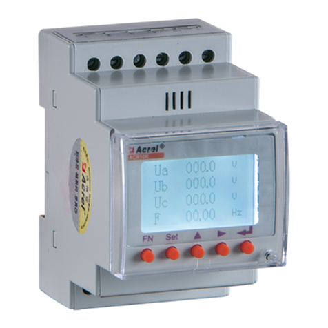
Acrel ACR10R-D TE Series Technical specifications

Acrel

Acrel ACR10R-D TE Series Technical specifications

Acrel ACR10R Series Owner's manual

Acrel

Acrel ACR10R Series Owner's manual

Acrel DTSD1352 Owner's manual

Acrel

Acrel DTSD1352 Owner's manual

Acrel APM830 Owner's manual

Acrel

Acrel APM830 Owner's manual

Acrel AIM-T500 User manual

Acrel

Acrel AIM-T500 User manual

Popular Measuring Instrument manuals by other brands

Powerfix Profi 278296 Operation and safety notes

Powerfix Profi

Powerfix Profi 278296 Operation and safety notes

Test Equipment Depot GVT-427B user manual

Test Equipment Depot

Test Equipment Depot GVT-427B user manual

Fieldpiece ACH Operator's manual

Fieldpiece

Fieldpiece ACH Operator's manual

FLYSURFER VIRON3 user manual

FLYSURFER

FLYSURFER VIRON3 user manual

GMW TG uni 1 operating manual

GMW

GMW TG uni 1 operating manual

Downeaster Wind & Weather Medallion Series instruction manual

Downeaster

Downeaster Wind & Weather Medallion Series instruction manual

Hanna Instruments HI96725C instruction manual

Hanna Instruments

Hanna Instruments HI96725C instruction manual

Nokeval KMR260 quick guide

Nokeval

Nokeval KMR260 quick guide

HOKUYO AUTOMATIC UBG-05LN instruction manual

HOKUYO AUTOMATIC

HOKUYO AUTOMATIC UBG-05LN instruction manual

Fluke 96000 Series Operator's manual

Fluke

Fluke 96000 Series Operator's manual

Test Products International SP565 user manual

Test Products International

Test Products International SP565 user manual

General Sleep Zmachine Insight+ DT-200 Service manual
General Sleep

General Sleep Zmachine Insight+ DT-200 Service manual
Sensa Core Lacto Spark user manual

Sensa Core

Sensa Core Lacto Spark user manual

VOLTCRAFT UTS-1980 operating instructions

VOLTCRAFT

VOLTCRAFT UTS-1980 operating instructions

EBCHQ 94915 Operation manual

EBCHQ

EBCHQ 94915 Operation manual

Balluff BIP LD2-T017-01-EP-S4 Series user guide

Balluff

Balluff BIP LD2-T017-01-EP-S4 Series user guide

Pulsar IMP Lite Series instruction manual

Pulsar

Pulsar IMP Lite Series instruction manual

ETCR 6800 user manual

ETCR

ETCR 6800 user manual

manuals.online logo
manuals.online logoBrands
  • About & Mission
  • Contact us
  • Privacy Policy
  • Terms and Conditions

Copyright 2025 Manuals.Online. All Rights Reserved.

External Meter Wiring Instruction
Interface:
Specification:
General
Model No.
AGF-AE-D/200
Rated Voltage-Line to N
120V
Rated Voltage-Line to Line
240V
Extended Voltage Range
88%~110%
AC Frequency
60Hz
Grids Supported
L1/L2/N/PE
Power Consumption
1.2W
CT Rated RMS Current
200A
Number of Supplied CTs
2
Standard Compliance
Safety
UL1741
Installation Specifications
Meter Dimensions(H*W*D)
2.13*3.45*2.05in (54.1*87.8*52mm)
CT Dimension (H×W×D)
2.76*2.15*1.54in(70.5*54.5*39mm)
Meter Weight
0.44lbs (0.2kg)
Operating Temp. Range
-30~55℃
Relative Humidity
5 - 90%
Meter Mounting Type
DIN-Rail 35mm
COMM Port
CT Input
AC Power Input
Status Indicator
Accessory List:
CT Connector
Installation and Cable Connection:
Refer to Meter Wire Diagram attached on the 3rd page for more details.
CAUTION: Make sure the power is cut off before installation.
CAUTION: The direction of CT must be the same as shown on the Wire Diagram.
1. Install one CT onto L1 and connect the CT to the Meter CT Input terminals “L1 CT” (Red wire
to “+” and black wire to “-”).
2. Install the other CT onto L2 and connect the CT to the Meter CT Input terminals “L2 CT” (Red
wire to “+” and black wire to “-”).
3. Connect Main Panel L1, L2, Neutral and Ground (PE) to the Meter AC Power Input terminals
ΦL1, ΦL2, N and Ground respectively.
4. Connect the Meter COMM Port “RS485 A+” and “RS485 B-” to the Universal PCS “RS485-1
#7” and “RS485-1 #8” respectively.
NOTE:
1. Mount the Meter solidly in the Main Panel or in a separate electrical box.
2. Use 24AWG copper wire for AC Power Input, and CAT5e (24AWG) for communication cable.
3. Two CTs are the same, although their cables are marked in different colors.
4. Refer to Terminal Disassembling Instruction attached on the 4th page to remove the wire
on the Meter CT Input terminals if needed.
5. Refer to Status Indicator Instruction attached on the 4th page for more information about
the Status LED.
6. Refer to the manual of the Meter for more information.
CT Direction
Universal PCS RS485-1 Port
RS485-1 Port
Details
L1 L2
N
Grid
L1 L2
N
Load
RS232
RS485-4 RS485-1
BCMS
N
L1 L2
PE
M
AGF-AE-D/200
Acrel
G
B-
A+ - + - +
L2 CT L1 CT
RS485
L2
L1
N
RS485-A
RS485-B
φL1φL2 N
Grid
Main Panel
L1
L2
Comm
N
Universal PCS
Meter Wire Diagram
Terminal Disassembling Instruction:
Step One Step Two Step Three
Status Indicator Instruction:
Indicator
Description
Troubleshooting
RUN
Blinking Green: Running normally
Solid Red>3s: Internal fault
Replace the Meter
Blinking Yellow: No communication
L1/L2
Solid Green>3s: No Current
Blinking Green: Positive power
Blinking Red: Negative power
Blinking Red & Green: High voltage>130V
Blinking Red & Yellow: Low voltage<70V
Blinking Yellow: Low voltage<30V
Solid Yellow>3s: Frequency abnormal,<45Hz or>70Hz
Choose Meter-Zero on the APP:
NOTE: Unless limits of battery power, the system starts to track the load on the meter.